2002 JEEP LIBERTY front panel
[x] Cancel search: front panelPage 1552 of 1803
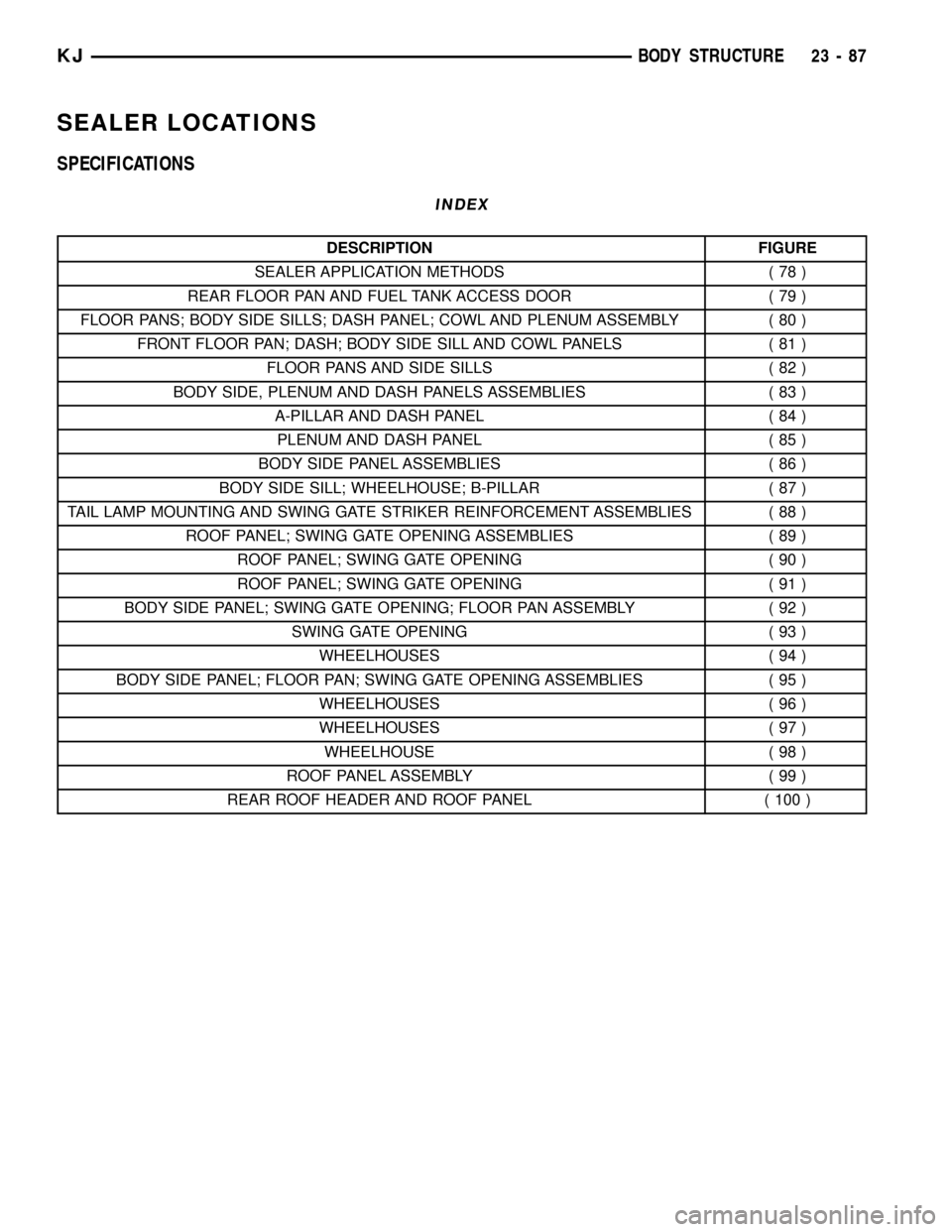
SEALER LOCATIONS
SPECIFICATIONS
INDEX
DESCRIPTION FIGURE
SEALER APPLICATION METHODS ( 78 )
REAR FLOOR PAN AND FUEL TANK ACCESS DOOR ( 79 )
FLOOR PANS; BODY SIDE SILLS; DASH PANEL; COWL AND PLENUM ASSEMBLY ( 80 )
FRONT FLOOR PAN; DASH; BODY SIDE SILL AND COWL PANELS ( 81 )
FLOOR PANS AND SIDE SILLS ( 82 )
BODY SIDE, PLENUM AND DASH PANELS ASSEMBLIES ( 83 )
A-PILLAR AND DASH PANEL ( 84 )
PLENUM AND DASH PANEL ( 85 )
BODY SIDE PANEL ASSEMBLIES ( 86 )
BODY SIDE SILL; WHEELHOUSE; B-PILLAR ( 87 )
TAIL LAMP MOUNTING AND SWING GATE STRIKER REINFORCEMENT ASSEMBLIES ( 88 )
ROOF PANEL; SWING GATE OPENING ASSEMBLIES ( 89 )
ROOF PANEL; SWING GATE OPENING ( 90 )
ROOF PANEL; SWING GATE OPENING ( 91 )
BODY SIDE PANEL; SWING GATE OPENING; FLOOR PAN ASSEMBLY ( 92 )
SWING GATE OPENING ( 93 )
WHEELHOUSES ( 94 )
BODY SIDE PANEL; FLOOR PAN; SWING GATE OPENING ASSEMBLIES ( 95 )
WHEELHOUSES ( 96 )
WHEELHOUSES ( 97 )
WHEELHOUSE ( 98 )
ROOF PANEL ASSEMBLY ( 99 )
REAR ROOF HEADER AND ROOF PANEL ( 100 )
KJBODY STRUCTURE 23 - 87
Page 1556 of 1803
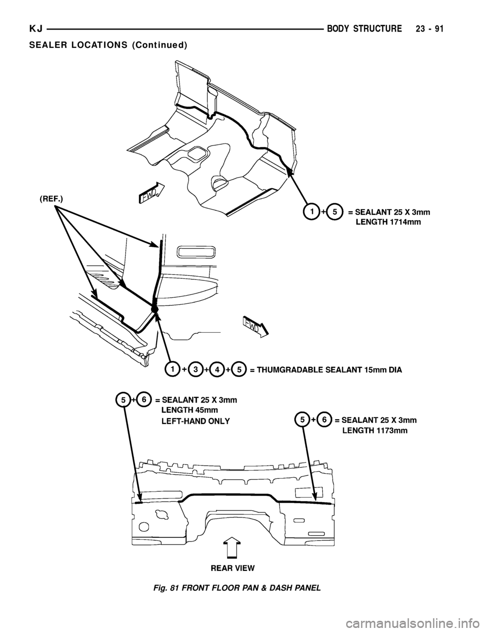
Fig. 81 FRONT FLOOR PAN & DASH PANEL
KJBODY STRUCTURE 23 - 91
SEALER LOCATIONS (Continued)
Page 1586 of 1803
DOOR - FRONT
TABLE OF CONTENTS
page page
CHECK STRAP
REMOVAL............................121
INSTALLATION........................121
DOOR
REMOVAL............................122
INSTALLATION........................122
DOOR GLASS
REMOVAL............................122
INSTALLATION........................122
EXTERIOR HANDLE
REMOVAL............................123
INSTALLATION........................123
GLASS RUN CHANNEL
REMOVAL............................123
INSTALLATION........................123
HINGE
REMOVAL............................123
INSTALLATION........................123
LATCH
REMOVAL............................124
INSTALLATION........................124ADJUSTMENTS
ADJUSTMENT.......................124
LATCH STRIKER
REMOVAL............................124
INSTALLATION........................124
LOCK CYLINDER
REMOVAL............................125
INSTALLATION........................125
TRIM PANEL
REMOVAL............................125
INSTALLATION........................126
WATERDAM
REMOVAL............................126
INSTALLATION........................126
WINDOW REGULATOR - MANUAL
REMOVAL............................126
INSTALLATION........................126
WINDOW REGULATOR - ELECTRIC
REMOVAL............................126
INSTALLATION........................126
CHECK STRAP
REMOVAL
(1) Remove the waterdam. (Refer to 23 - BODY/
DOOR - FRONT/WATERDAM - REMOVAL)
(2) Remove screws attaching door check to A-pillar.
(3) Remove the two nuts and remove the door
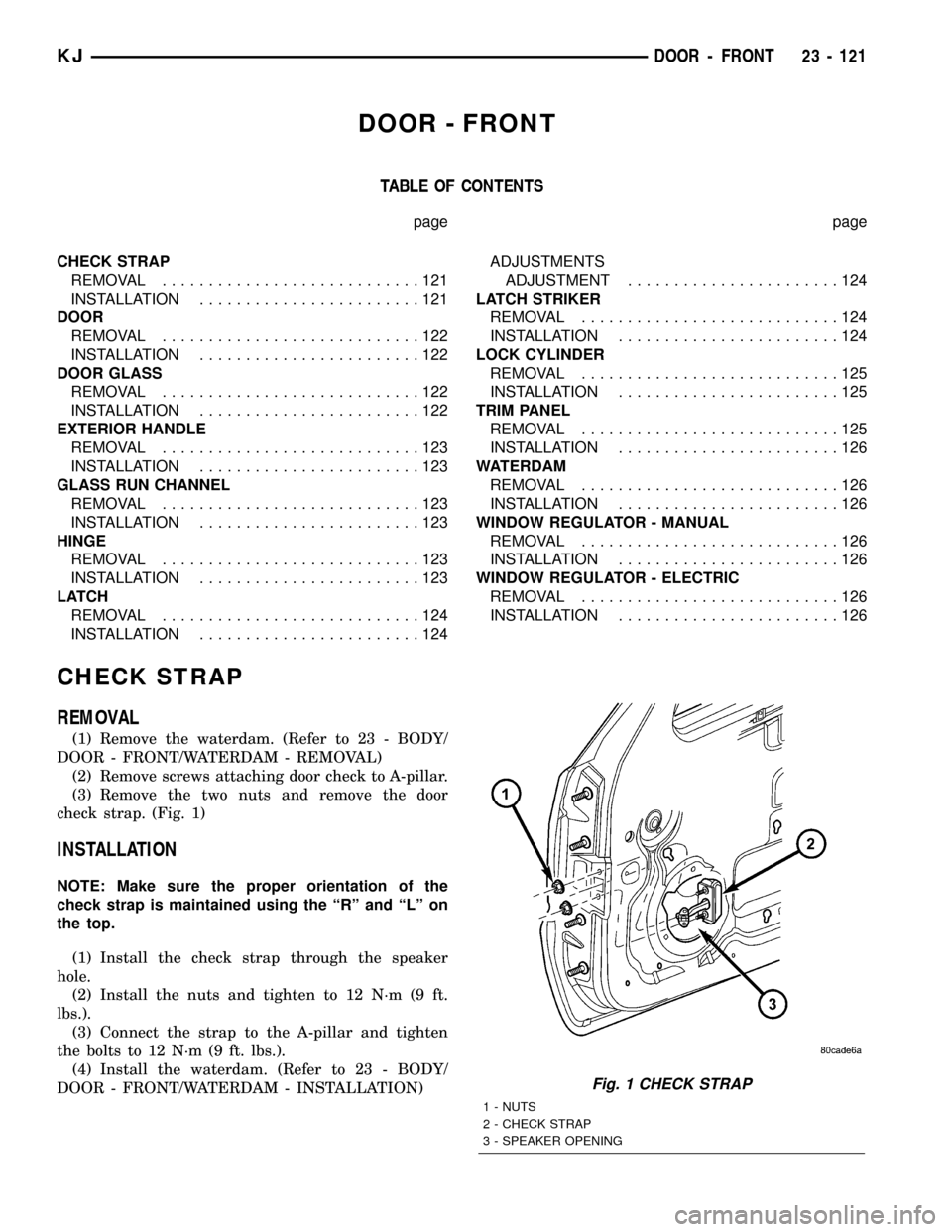
check strap. (Fig. 1)
INSTALLATION
NOTE: Make sure the proper orientation of the
check strap is maintained using the ªRº and ªLº on
the top.
(1) Install the check strap through the speaker
hole.
(2) Install the nuts and tighten to 12 N´m (9 ft.
lbs.).
(3) Connect the strap to the A-pillar and tighten
the bolts to 12 N´m (9 ft. lbs.).
(4) Install the waterdam. (Refer to 23 - BODY/
DOOR - FRONT/WATERDAM - INSTALLATION)
Fig. 1 CHECK STRAP
1 - NUTS
2 - CHECK STRAP
3 - SPEAKER OPENING
KJDOOR - FRONT 23 - 121
Page 1590 of 1803
LOCK CYLINDER
REMOVAL
(1) Remove the exterior handle. (Refer to 23 -
BODY/DOOR - FRONT/EXTERIOR HANDLE -
REMOVAL)
(2) Remove the clip and remove the lock cylinder
lever and switch, if equipped.
(3) Remove the screw and remove the lock cylin-
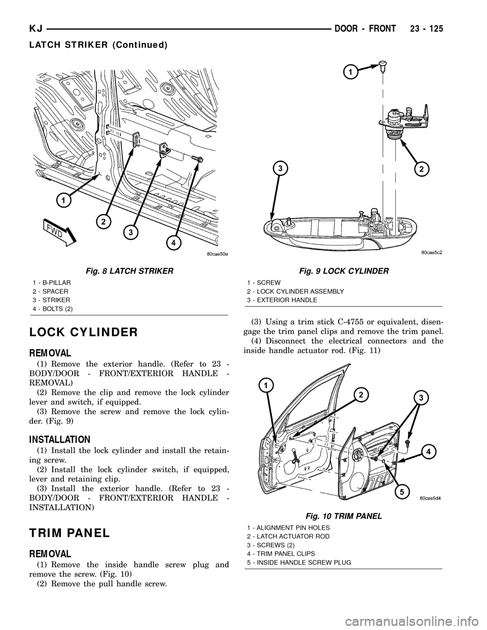
der. (Fig. 9)
INSTALLATION
(1) Install the lock cylinder and install the retain-
ing screw.
(2) Install the lock cylinder switch, if equipped,
lever and retaining clip.
(3) Install the exterior handle. (Refer to 23 -
BODY/DOOR - FRONT/EXTERIOR HANDLE -
INSTALLATION)
TRIM PANEL
REMOVAL
(1) Remove the inside handle screw plug and
remove the screw. (Fig. 10)
(2) Remove the pull handle screw.(3) Using a trim stick C-4755 or equivalent, disen-
gage the trim panel clips and remove the trim panel.
(4) Disconnect the electrical connectors and the
inside handle actuator rod. (Fig. 11)
Fig. 8 LATCH STRIKER
1 - B-PILLAR
2 - SPACER
3 - STRIKER
4 - BOLTS (2)
Fig. 9 LOCK CYLINDER
1 - SCREW
2 - LOCK CYLINDER ASSEMBLY
3 - EXTERIOR HANDLE
Fig. 10 TRIM PANEL
1 - ALIGNMENT PIN HOLES
2 - LATCH ACTUATOR ROD
3 - SCREWS (2)
4 - TRIM PANEL CLIPS
5 - INSIDE HANDLE SCREW PLUG
KJDOOR - FRONT 23 - 125
LATCH STRIKER (Continued)
Page 1591 of 1803
INSTALLATION
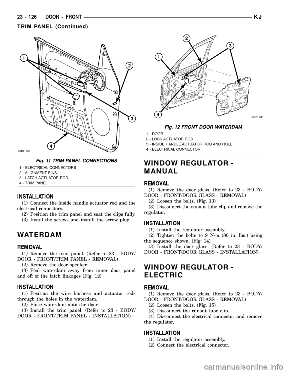
(1) Connect the inside handle actuator rod and the
electrical connectors.
(2) Position the trim panel and seat the clips fully.
(3) Instal the screws and install the screw plug.
WATERDAM
REMOVAL
(1) Remove the trim panel. (Refer to 23 - BODY/
DOOR - FRONT/TRIM PANEL - REMOVAL)
(2) Remove the door speaker.
(3) Peal waterdam away from inner door panel
and off of the latch linkages (Fig. 12).
INSTALLATION
(1) Position the wire harness and actuator rods
through the holes in the waterdam.
(2) Place waterdam onto the door.
(3) Install the trim panel. (Refer to 23 - BODY/
DOOR - FRONT/TRIM PANEL - INSTALLATION)
WINDOW REGULATOR -
MANUAL
REMOVAL
(1) Remove the door glass. (Refer to 23 - BODY/
DOOR - FRONT/DOOR GLASS - REMOVAL)
(2) Loosen the bolts. (Fig. 13)
(3) Disconnect the runout tube clip and remove the
regulator.
INSTALLATION
(1) Install the regulator assembly.
(2) Tighten the bolts to 9 N´m (80 in. lbs.) using
the sequence shown. (Fig. 14)
(3) Install the door glass. (Refer to 23 - BODY/
DOOR - FRONT/DOOR GLASS - INSTALLATION)
WINDOW REGULATOR -
ELECTRIC
REMOVAL
(1) Remove the door glass. (Refer to 23 - BODY/
DOOR - FRONT/DOOR GLASS - REMOVAL)
(2) Loosen the bolts. (Fig. 15)
(3) Disconnect the runout tube clip.
(4) Disconnect the electrical connector and remove
the regulator.
INSTALLATION
(1) Install the regulator assembly.
(2) Connect the electrical connector.
Fig. 11 TRIM PANEL CONNECTIONS
1 - ELECTRICAL CONNECTORS
2 - ALIGNMENT PINS
3 - LATCH ACTUATOR ROD
4 - TRIM PANEL
Fig. 12 FRONT DOOR WATERDAM
1 - DOOR
2 - LOCK ACTUATOR ROD
3 - INSIDE HANDLE ACTUATOR ROD AND HOLE
4 - ELECTRICAL CONNECTOR
23 - 126 DOOR - FRONTKJ
TRIM PANEL (Continued)
Page 1594 of 1803
DOOR
REMOVAL
(1) Disconnect the door wire harness electrical con-
nector at the b-pillar.
(2) Disconnect the check strap from the b-pillar.
(Refer to 23 - BODY/DOORS - REAR/CHECK STRAP
- REMOVAL)
(3) Support the door with a suitable lifting device.
NOTE: The epoxy washers should not be removed
from the hinge. If the washers are removed the door
may have to be re-adjusted.
(4) Remove the nuts attaching the door hinges to
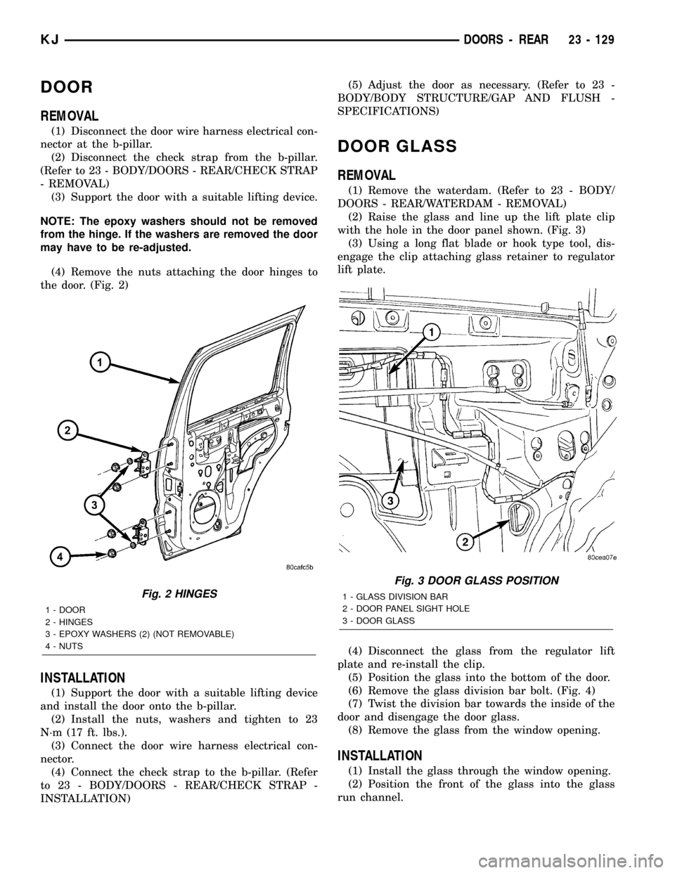
the door. (Fig. 2)
INSTALLATION
(1) Support the door with a suitable lifting device
and install the door onto the b-pillar.
(2) Install the nuts, washers and tighten to 23
N´m (17 ft. lbs.).
(3) Connect the door wire harness electrical con-
nector.
(4) Connect the check strap to the b-pillar. (Refer
to 23 - BODY/DOORS - REAR/CHECK STRAP -
INSTALLATION)(5) Adjust the door as necessary. (Refer to 23 -
BODY/BODY STRUCTURE/GAP AND FLUSH -
SPECIFICATIONS)
DOOR GLASS
REMOVAL
(1) Remove the waterdam. (Refer to 23 - BODY/
DOORS - REAR/WATERDAM - REMOVAL)
(2) Raise the glass and line up the lift plate clip
with the hole in the door panel shown. (Fig. 3)
(3) Using a long flat blade or hook type tool, dis-
engage the clip attaching glass retainer to regulator
lift plate.
(4) Disconnect the glass from the regulator lift
plate and re-install the clip.
(5) Position the glass into the bottom of the door.
(6) Remove the glass division bar bolt. (Fig. 4)
(7) Twist the division bar towards the inside of the
door and disengage the door glass.
(8) Remove the glass from the window opening.
INSTALLATION
(1) Install the glass through the window opening.
(2) Position the front of the glass into the glass
run channel.
Fig. 2 HINGES
1 - DOOR
2 - HINGES
3 - EPOXY WASHERS (2) (NOT REMOVABLE)
4 - NUTS
Fig. 3 DOOR GLASS POSITION
1 - GLASS DIVISION BAR
2 - DOOR PANEL SIGHT HOLE
3 - DOOR GLASS
KJDOORS - REAR 23 - 129
Page 1605 of 1803
EXTERIOR
TABLE OF CONTENTS
page page
BODY SIDE MOLDINGS
REMOVAL............................140
INSTALLATION........................140
COWL GRILLE
REMOVAL............................140
INSTALLATION........................140
EXTERIOR NAME PLATES
REMOVAL............................140
INSTALLATION........................141
FRONT FENDER
REMOVAL............................141
INSTALLATION........................141
FUEL FILL DOOR/HOUSING
REMOVAL............................141
INSTALLATION........................141
GRILLE
REMOVAL............................142
INSTALLATION........................142
GRILLE OPENING REINFORCEMENT
REMOVAL............................142
INSTALLATION........................142FRONT WHEELHOUSE SPLASH SHIELD
REMOVAL............................143
INSTALLATION........................143
LUGGAGE RACK
REMOVAL............................144
INSTALLATION........................144
REAR WHEELHOUSE SPLASH SHIELD
REMOVAL............................144
INSTALLATION........................144
SIDE VIEW MIRROR
REMOVAL............................145
INSTALLATION........................145
FRONT WHEEL OPENING FLARE MOLDINGS
REMOVAL............................145
INSTALLATION........................145
REAR WHEEL OPENING FLARE MOLDINGS
REMOVAL............................145
INSTALLATION........................145
RADIATOR CROSSMEMBER
REMOVAL............................146
INSTALLATION........................146
BODY SIDE MOLDINGS
REMOVAL
(1) Using a trim stick C-4755 or equivalent,
remove and discard the molding from the outside of
the door.
INSTALLATION
(1) Thoroughly clean all residue from the body side
molding attachment area of the door.
(2) Wipe area clean with a 50% solution of water
and alcohol and wipe dry.
(3) Apply new body side molding using the locators
in the door and apply pressure of approximately 40
p.s.i. over the entire surface of the molding.
COWL GRILLE
REMOVAL
(1) Remove the hood seal.
(2) Remove the wiper arms. (Refer to 8 - ELEC-
TRICAL/WIPERS/WASHERS/WIPER ARMS -
REMOVAL)
(3) Remove the four plastic retainers and remove
the cowl grill.
INSTALLATION
(1) Position the cowl grill and engage the nine
clips to the bottom of the windshield.
(2) Install the five plastic retainers.
(3) Install the wiper arms. (Refer to 8 - ELECTRI-
CAL/WIPERS/WASHERS/WIPER ARMS - INSTAL-
LATION)
(4) Install the hood seal.
EXTERIOR NAME PLATES
REMOVAL
NOTE: Exterior nameplates are attached to body
panels with adhesive tape.
(1) Apply a length of masking tape on the body,
parallel to the top edge of the nameplate to use as a
guide, if necessary.
(2) If temperature is below 21ÉC (70ÉF) warm
emblem with a heat lamp or gun. Do not exceed 52ÉC
(120ÉF) when heating emblem.
(3) Using a trim stick C-4755 or equivalent, behind
the emblem to separate the adhesive backing from
the body.
23 - 140 EXTERIORKJ
Page 1610 of 1803
SIDE VIEW MIRROR
REMOVAL
(1) Remove the trim panel. (Refer to 23 - BODY/
DOOR - FRONT/TRIM PANEL - REMOVAL)
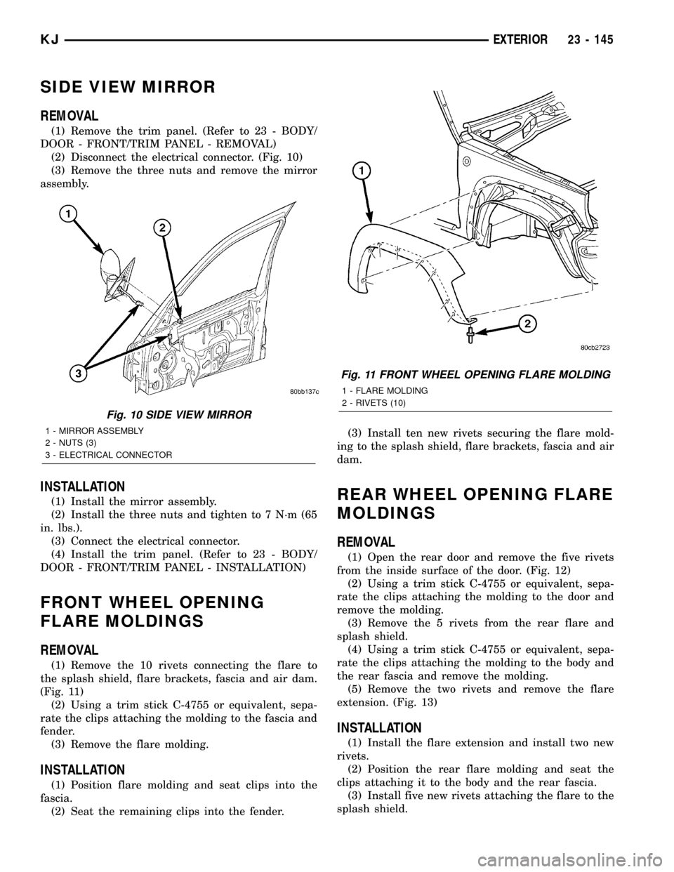
(2) Disconnect the electrical connector. (Fig. 10)
(3) Remove the three nuts and remove the mirror
assembly.
INSTALLATION
(1) Install the mirror assembly.
(2) Install the three nuts and tighten to 7 N´m (65
in. lbs.).
(3) Connect the electrical connector.
(4) Install the trim panel. (Refer to 23 - BODY/
DOOR - FRONT/TRIM PANEL - INSTALLATION)
FRONT WHEEL OPENING
FLARE MOLDINGS
REMOVAL
(1) Remove the 10 rivets connecting the flare to
the splash shield, flare brackets, fascia and air dam.
(Fig. 11)
(2) Using a trim stick C-4755 or equivalent, sepa-
rate the clips attaching the molding to the fascia and
fender.
(3) Remove the flare molding.
INSTALLATION
(1) Position flare molding and seat clips into the
fascia.
(2) Seat the remaining clips into the fender.(3) Install ten new rivets securing the flare mold-
ing to the splash shield, flare brackets, fascia and air
dam.
REAR WHEEL OPENING FLARE
MOLDINGS
REMOVAL
(1) Open the rear door and remove the five rivets
from the inside surface of the door. (Fig. 12)
(2) Using a trim stick C-4755 or equivalent, sepa-
rate the clips attaching the molding to the door and
remove the molding.
(3) Remove the 5 rivets from the rear flare and
splash shield.
(4) Using a trim stick C-4755 or equivalent, sepa-
rate the clips attaching the molding to the body and
the rear fascia and remove the molding.
(5) Remove the two rivets and remove the flare
extension. (Fig. 13)
INSTALLATION
(1) Install the flare extension and install two new
rivets.
(2) Position the rear flare molding and seat the
clips attaching it to the body and the rear fascia.
(3) Install five new rivets attaching the flare to the
splash shield.
Fig. 10 SIDE VIEW MIRROR
1 - MIRROR ASSEMBLY
2 - NUTS (3)
3 - ELECTRICAL CONNECTOR
Fig. 11 FRONT WHEEL OPENING FLARE MOLDING
1 - FLARE MOLDING
2 - RIVETS (10)
KJEXTERIOR 23 - 145