2002 JEEP LIBERTY Air bag
[x] Cancel search: Air bagPage 1160 of 1803
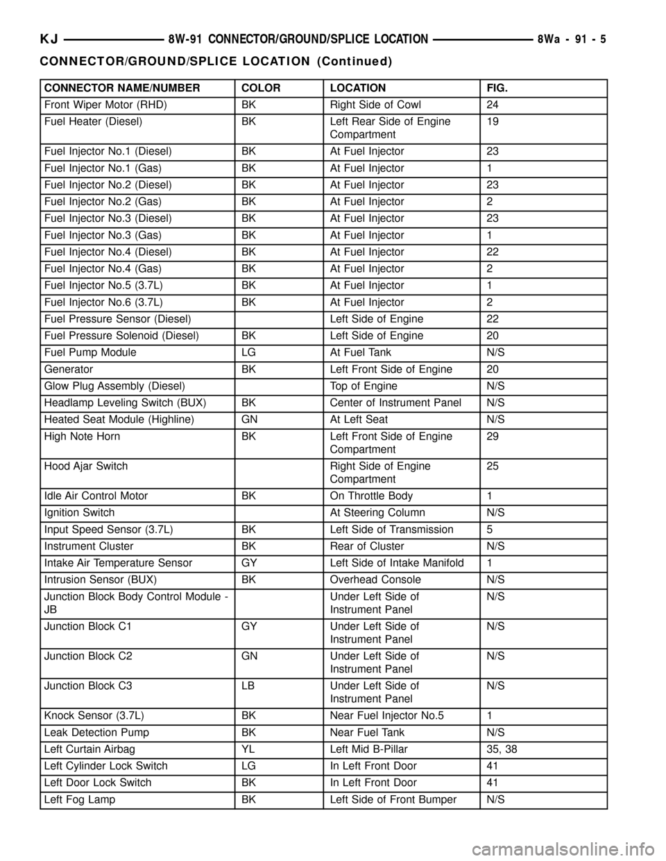
CONNECTOR NAME/NUMBER COLOR LOCATION FIG.
Front Wiper Motor (RHD) BK Right Side of Cowl 24
Fuel Heater (Diesel) BK Left Rear Side of Engine
Compartment19
Fuel Injector No.1 (Diesel) BK At Fuel Injector 23
Fuel Injector No.1 (Gas) BK At Fuel Injector 1
Fuel Injector No.2 (Diesel) BK At Fuel Injector 23
Fuel Injector No.2 (Gas) BK At Fuel Injector 2
Fuel Injector No.3 (Diesel) BK At Fuel Injector 23
Fuel Injector No.3 (Gas) BK At Fuel Injector 1
Fuel Injector No.4 (Diesel) BK At Fuel Injector 22
Fuel Injector No.4 (Gas) BK At Fuel Injector 2
Fuel Injector No.5 (3.7L) BK At Fuel Injector 1
Fuel Injector No.6 (3.7L) BK At Fuel Injector 2
Fuel Pressure Sensor (Diesel) Left Side of Engine 22
Fuel Pressure Solenoid (Diesel) BK Left Side of Engine 20
Fuel Pump Module LG At Fuel Tank N/S
Generator BK Left Front Side of Engine 20
Glow Plug Assembly (Diesel) Top of Engine N/S
Headlamp Leveling Switch (BUX) BK Center of Instrument Panel N/S
Heated Seat Module (Highline) GN At Left Seat N/S
High Note Horn BK Left Front Side of Engine
Compartment29
Hood Ajar Switch Right Side of Engine
Compartment25
Idle Air Control Motor BK On Throttle Body 1
Ignition Switch At Steering Column N/S
Input Speed Sensor (3.7L) BK Left Side of Transmission 5
Instrument Cluster BK Rear of Cluster N/S
Intake Air Temperature Sensor GY Left Side of Intake Manifold 1
Intrusion Sensor (BUX) BK Overhead Console N/S
Junction Block Body Control Module -
JBUnder Left Side of
Instrument PanelN/S
Junction Block C1 GY Under Left Side of
Instrument PanelN/S
Junction Block C2 GN Under Left Side of
Instrument PanelN/S
Junction Block C3 LB Under Left Side of
Instrument PanelN/S
Knock Sensor (3.7L) BK Near Fuel Injector No.5 1
Leak Detection Pump BK Near Fuel Tank N/S
Left Curtain Airbag YL Left Mid B-Pillar 35, 38
Left Cylinder Lock Switch LG In Left Front Door 41
Left Door Lock Switch BK In Left Front Door 41
Left Fog Lamp BK Left Side of Front Bumper N/S
KJ8W-91 CONNECTOR/GROUND/SPLICE LOCATION8Wa-91-5
CONNECTOR/GROUND/SPLICE LOCATION (Continued)
Page 1161 of 1803
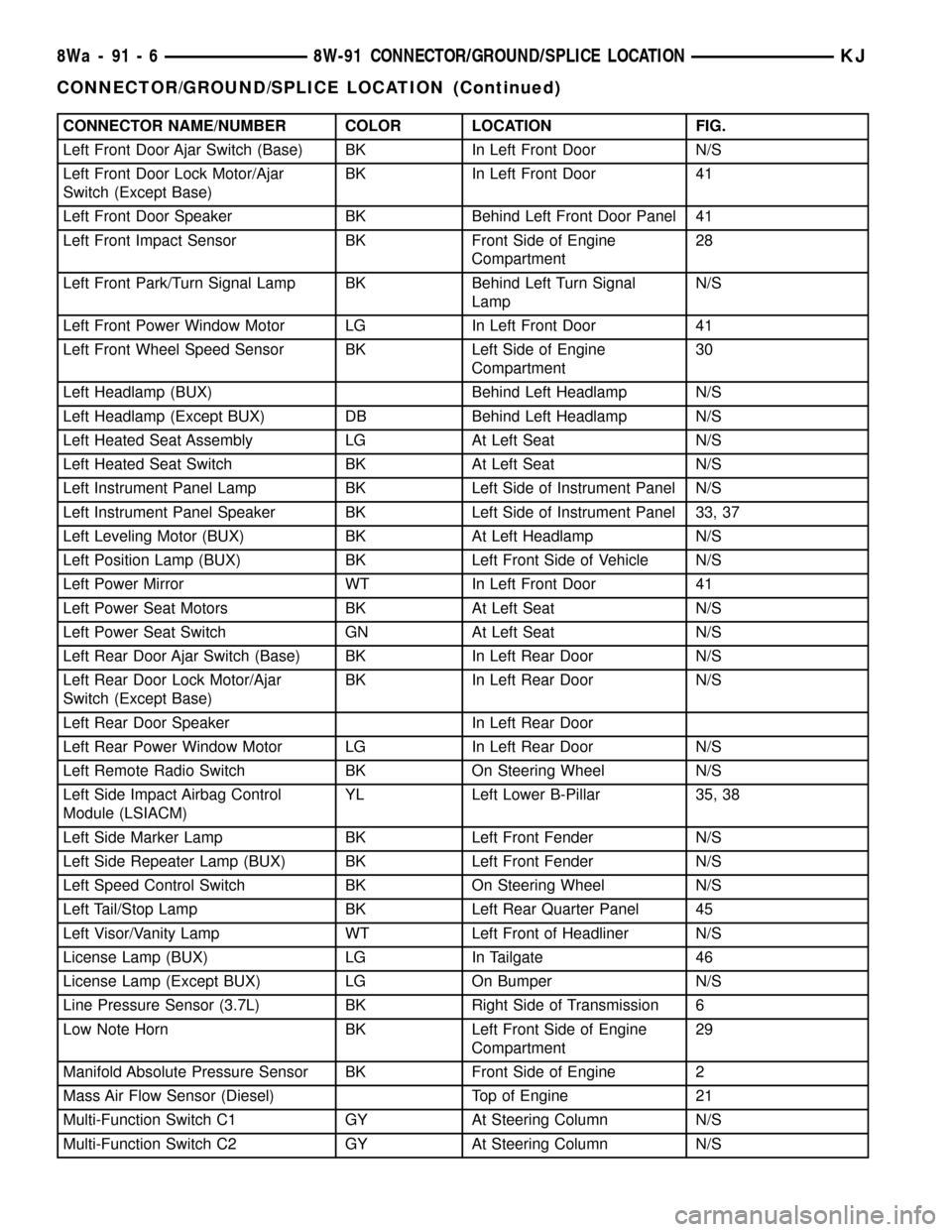
CONNECTOR NAME/NUMBER COLOR LOCATION FIG.
Left Front Door Ajar Switch (Base) BK In Left Front Door N/S
Left Front Door Lock Motor/Ajar
Switch (Except Base)BK In Left Front Door 41
Left Front Door Speaker BK Behind Left Front Door Panel 41
Left Front Impact Sensor BK Front Side of Engine
Compartment28
Left Front Park/Turn Signal Lamp BK Behind Left Turn Signal
LampN/S
Left Front Power Window Motor LG In Left Front Door 41
Left Front Wheel Speed Sensor BK Left Side of Engine
Compartment30
Left Headlamp (BUX) Behind Left Headlamp N/S
Left Headlamp (Except BUX) DB Behind Left Headlamp N/S
Left Heated Seat Assembly LG At Left Seat N/S
Left Heated Seat Switch BK At Left Seat N/S
Left Instrument Panel Lamp BK Left Side of Instrument Panel N/S
Left Instrument Panel Speaker BK Left Side of Instrument Panel 33, 37
Left Leveling Motor (BUX) BK At Left Headlamp N/S
Left Position Lamp (BUX) BK Left Front Side of Vehicle N/S
Left Power Mirror WT In Left Front Door 41
Left Power Seat Motors BK At Left Seat N/S
Left Power Seat Switch GN At Left Seat N/S
Left Rear Door Ajar Switch (Base) BK In Left Rear Door N/S
Left Rear Door Lock Motor/Ajar
Switch (Except Base)BK In Left Rear Door N/S
Left Rear Door Speaker In Left Rear Door
Left Rear Power Window Motor LG In Left Rear Door N/S
Left Remote Radio Switch BK On Steering Wheel N/S
Left Side Impact Airbag Control
Module (LSIACM)YL Left Lower B-Pillar 35, 38
Left Side Marker Lamp BK Left Front Fender N/S
Left Side Repeater Lamp (BUX) BK Left Front Fender N/S
Left Speed Control Switch BK On Steering Wheel N/S
Left Tail/Stop Lamp BK Left Rear Quarter Panel 45
Left Visor/Vanity Lamp WT Left Front of Headliner N/S
License Lamp (BUX) LG In Tailgate 46
License Lamp (Except BUX) LG On Bumper N/S
Line Pressure Sensor (3.7L) BK Right Side of Transmission 6
Low Note Horn BK Left Front Side of Engine
Compartment29
Manifold Absolute Pressure Sensor BK Front Side of Engine 2
Mass Air Flow Sensor (Diesel) Top of Engine 21
Multi-Function Switch C1 GY At Steering Column N/S
Multi-Function Switch C2 GY At Steering Column N/S
8Wa - 91 - 6 8W-91 CONNECTOR/GROUND/SPLICE LOCATIONKJ
CONNECTOR/GROUND/SPLICE LOCATION (Continued)
Page 1162 of 1803
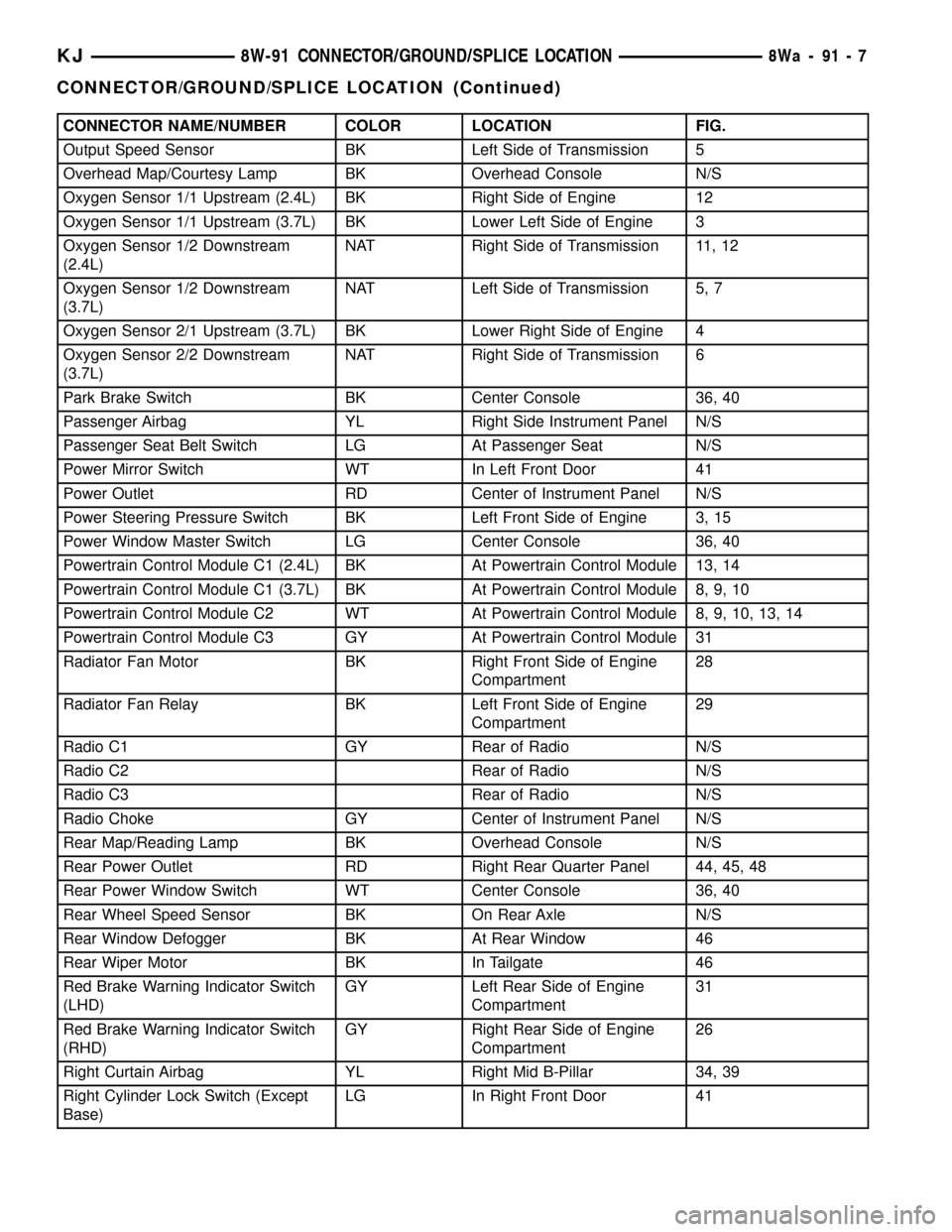
CONNECTOR NAME/NUMBER COLOR LOCATION FIG.
Output Speed Sensor BK Left Side of Transmission 5
Overhead Map/Courtesy Lamp BK Overhead Console N/S
Oxygen Sensor 1/1 Upstream (2.4L) BK Right Side of Engine 12
Oxygen Sensor 1/1 Upstream (3.7L) BK Lower Left Side of Engine 3
Oxygen Sensor 1/2 Downstream
(2.4L)NAT Right Side of Transmission 11, 12
Oxygen Sensor 1/2 Downstream
(3.7L)NAT Left Side of Transmission 5, 7
Oxygen Sensor 2/1 Upstream (3.7L) BK Lower Right Side of Engine 4
Oxygen Sensor 2/2 Downstream
(3.7L)NAT Right Side of Transmission 6
Park Brake Switch BK Center Console 36, 40
Passenger Airbag YL Right Side Instrument Panel N/S
Passenger Seat Belt Switch LG At Passenger Seat N/S
Power Mirror Switch WT In Left Front Door 41
Power Outlet RD Center of Instrument Panel N/S
Power Steering Pressure Switch BK Left Front Side of Engine 3, 15
Power Window Master Switch LG Center Console 36, 40
Powertrain Control Module C1 (2.4L) BK At Powertrain Control Module 13, 14
Powertrain Control Module C1 (3.7L) BK At Powertrain Control Module 8, 9, 10
Powertrain Control Module C2 WT At Powertrain Control Module 8, 9, 10, 13, 14
Powertrain Control Module C3 GY At Powertrain Control Module 31
Radiator Fan Motor BK Right Front Side of Engine
Compartment28
Radiator Fan Relay BK Left Front Side of Engine
Compartment29
Radio C1 GY Rear of Radio N/S
Radio C2 Rear of Radio N/S
Radio C3 Rear of Radio N/S
Radio Choke GY Center of Instrument Panel N/S
Rear Map/Reading Lamp BK Overhead Console N/S
Rear Power Outlet RD Right Rear Quarter Panel 44, 45, 48
Rear Power Window Switch WT Center Console 36, 40
Rear Wheel Speed Sensor BK On Rear Axle N/S
Rear Window Defogger BK At Rear Window 46
Rear Wiper Motor BK In Tailgate 46
Red Brake Warning Indicator Switch
(LHD)GY Left Rear Side of Engine
Compartment31
Red Brake Warning Indicator Switch
(RHD)GY Right Rear Side of Engine
Compartment26
Right Curtain Airbag YL Right Mid B-Pillar 34, 39
Right Cylinder Lock Switch (Except
Base)LG In Right Front Door 41
KJ8W-91 CONNECTOR/GROUND/SPLICE LOCATION8Wa-91-7
CONNECTOR/GROUND/SPLICE LOCATION (Continued)
Page 1163 of 1803
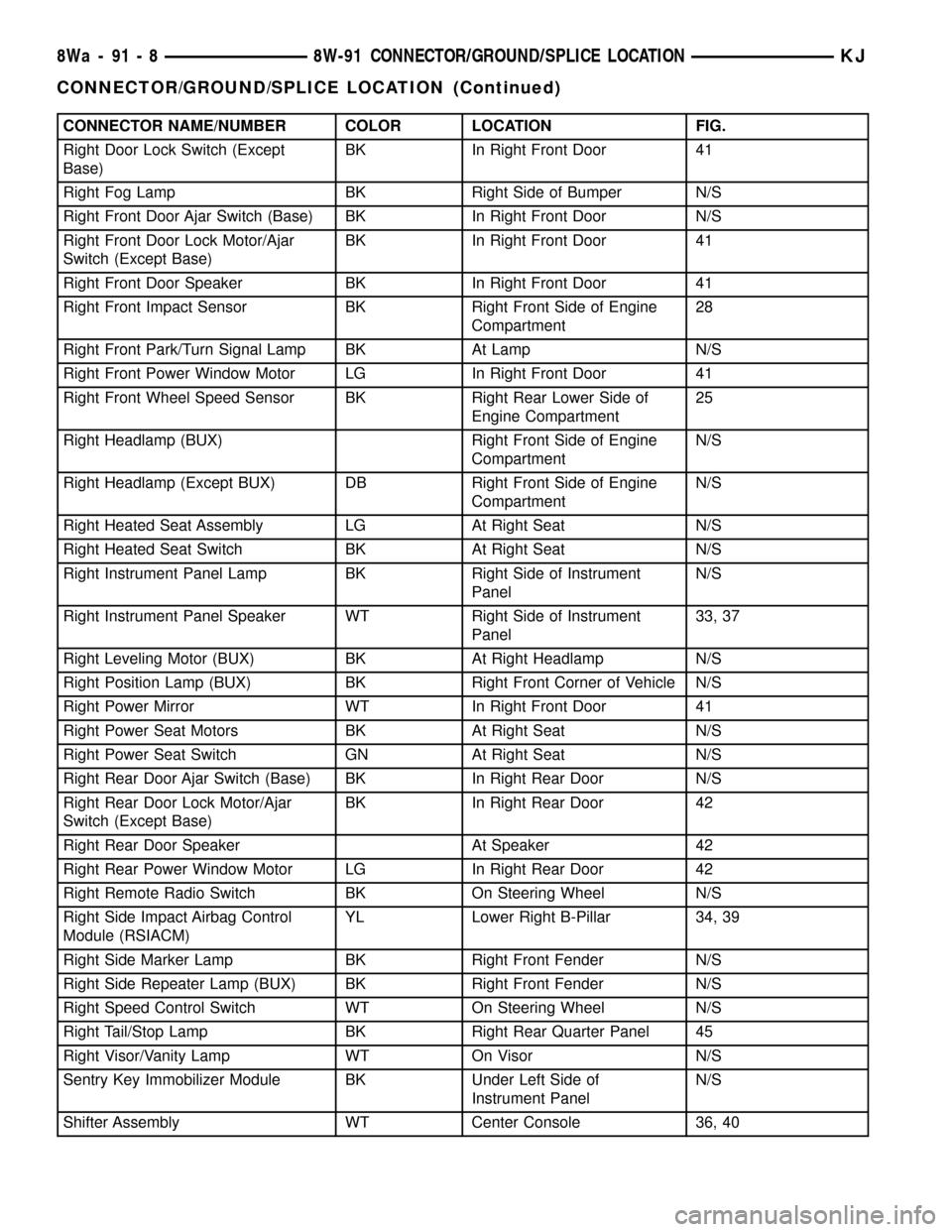
CONNECTOR NAME/NUMBER COLOR LOCATION FIG.
Right Door Lock Switch (Except
Base)BK In Right Front Door 41
Right Fog Lamp BK Right Side of Bumper N/S
Right Front Door Ajar Switch (Base) BK In Right Front Door N/S
Right Front Door Lock Motor/Ajar
Switch (Except Base)BK In Right Front Door 41
Right Front Door Speaker BK In Right Front Door 41
Right Front Impact Sensor BK Right Front Side of Engine
Compartment28
Right Front Park/Turn Signal Lamp BK At Lamp N/S
Right Front Power Window Motor LG In Right Front Door 41
Right Front Wheel Speed Sensor BK Right Rear Lower Side of
Engine Compartment25
Right Headlamp (BUX) Right Front Side of Engine
CompartmentN/S
Right Headlamp (Except BUX) DB Right Front Side of Engine
CompartmentN/S
Right Heated Seat Assembly LG At Right Seat N/S
Right Heated Seat Switch BK At Right Seat N/S
Right Instrument Panel Lamp BK Right Side of Instrument
PanelN/S
Right Instrument Panel Speaker WT Right Side of Instrument
Panel33, 37
Right Leveling Motor (BUX) BK At Right Headlamp N/S
Right Position Lamp (BUX) BK Right Front Corner of Vehicle N/S
Right Power Mirror WT In Right Front Door 41
Right Power Seat Motors BK At Right Seat N/S
Right Power Seat Switch GN At Right Seat N/S
Right Rear Door Ajar Switch (Base) BK In Right Rear Door N/S
Right Rear Door Lock Motor/Ajar
Switch (Except Base)BK In Right Rear Door 42
Right Rear Door Speaker At Speaker 42
Right Rear Power Window Motor LG In Right Rear Door 42
Right Remote Radio Switch BK On Steering Wheel N/S
Right Side Impact Airbag Control
Module (RSIACM)YL Lower Right B-Pillar 34, 39
Right Side Marker Lamp BK Right Front Fender N/S
Right Side Repeater Lamp (BUX) BK Right Front Fender N/S
Right Speed Control Switch WT On Steering Wheel N/S
Right Tail/Stop Lamp BK Right Rear Quarter Panel 45
Right Visor/Vanity Lamp WT On Visor N/S
Sentry Key Immobilizer Module BK Under Left Side of
Instrument PanelN/S
Shifter Assembly WT Center Console 36, 40
8Wa - 91 - 8 8W-91 CONNECTOR/GROUND/SPLICE LOCATIONKJ
CONNECTOR/GROUND/SPLICE LOCATION (Continued)
Page 1166 of 1803
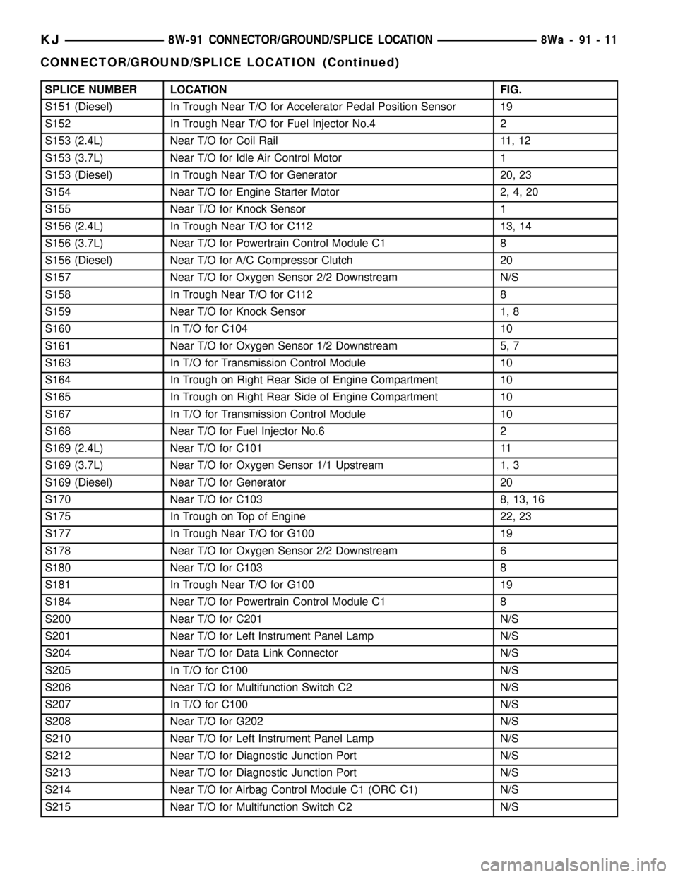
SPLICE NUMBER LOCATION FIG.
S151 (Diesel) In Trough Near T/O for Accelerator Pedal Position Sensor 19
S152 In Trough Near T/O for Fuel Injector No.4 2
S153 (2.4L) Near T/O for Coil Rail 11, 12
S153 (3.7L) Near T/O for Idle Air Control Motor 1
S153 (Diesel) In Trough Near T/O for Generator 20, 23
S154 Near T/O for Engine Starter Motor 2, 4, 20
S155 Near T/O for Knock Sensor 1
S156 (2.4L) In Trough Near T/O for C112 13, 14
S156 (3.7L) Near T/O for Powertrain Control Module C1 8
S156 (Diesel) Near T/O for A/C Compressor Clutch 20
S157 Near T/O for Oxygen Sensor 2/2 Downstream N/S
S158 In Trough Near T/O for C112 8
S159 Near T/O for Knock Sensor 1, 8
S160 In T/O for C104 10
S161 Near T/O for Oxygen Sensor 1/2 Downstream 5, 7
S163 In T/O for Transmission Control Module 10
S164 In Trough on Right Rear Side of Engine Compartment 10
S165 In Trough on Right Rear Side of Engine Compartment 10
S167 In T/O for Transmission Control Module 10
S168 Near T/O for Fuel Injector No.6 2
S169 (2.4L) Near T/O for C101 11
S169 (3.7L) Near T/O for Oxygen Sensor 1/1 Upstream 1, 3
S169 (Diesel) Near T/O for Generator 20
S170 Near T/O for C103 8, 13, 16
S175 In Trough on Top of Engine 22, 23
S177 In Trough Near T/O for G100 19
S178 Near T/O for Oxygen Sensor 2/2 Downstream 6
S180 Near T/O for C103 8
S181 In Trough Near T/O for G100 19
S184 Near T/O for Powertrain Control Module C1 8
S200 Near T/O for C201 N/S
S201 Near T/O for Left Instrument Panel Lamp N/S
S204 Near T/O for Data Link Connector N/S
S205 In T/O for C100 N/S
S206 Near T/O for Multifunction Switch C2 N/S
S207 In T/O for C100 N/S
S208 Near T/O for G202 N/S
S210 Near T/O for Left Instrument Panel Lamp N/S
S212 Near T/O for Diagnostic Junction Port N/S
S213 Near T/O for Diagnostic Junction Port N/S
S214 Near T/O for Airbag Control Module C1 (ORC C1) N/S
S215 Near T/O for Multifunction Switch C2 N/S
KJ8W-91 CONNECTOR/GROUND/SPLICE LOCATION8Wa-91-11
CONNECTOR/GROUND/SPLICE LOCATION (Continued)
Page 1435 of 1803

COLUMN
TABLE OF CONTENTS
page page
COLUMN
DESCRIPTION..........................5
OPERATION - SERVICE PRECAUTIONS......5
REMOVAL.............................5
INSTALLATION..........................7
SPECIFICATIONS
TORQUE CHART......................8
SPECIAL TOOLS
STEERING COLUMN....................8
IGNITION SWITCH
DESCRIPTION..........................8
DIAGNOSIS AND TESTING - IGNITION
SWITCH.............................8
REMOVAL
IGNITION SWITCH REMOVAL.............9INSTALLATION
IGNITION SWITCH INSTALLATION.........9
KEY-IN IGNITION SWITCH
DESCRIPTION.........................10
DIAGNOSIS AND TESTING - KEY-IN IGNITION
SWITCH............................10
LOCK CYLINDER
REMOVAL.............................10
INSTALLATION.........................11
INTERMEDIATE SHAFT
REMOVAL.............................11
INSTALLATION.........................11
STEERING WHEEL
REMOVAL.............................12
INSTALLATION.........................12
COLUMN
DESCRIPTION
The standard non-tilt and tilt steering column has
been designed to be serviced as an assembly. The col-
umn is connected to the steering gear with a one
piece shaft. The upper half has a support bearing
mounted to a bracket. The bracket mounts to the
frame rail with two nuts. The shaft is serviceable.
The key cylinder, switches, clock spring, trim shrouds
and steering wheel are serviced separately.
OPERATION - SERVICE PRECAUTIONS
Safety goggles should be worn at all times when
working on steering columns.
To service the steering wheel, switches or airbag,
refer to Electrical - Restraints and follow all WARN-
INGS and CAUTIONS.
WARNING: THE AIRBAG SYSTEM IS A SENSITIVE,
COMPLEX ELECTRO-MECHANICAL UNIT. BEFORE
ATTEMPTING TO DIAGNOSE, REMOVE OR INSTALL
THE AIRBAG SYSTEM COMPONENTS YOU MUST
FIRST DISCONNECT AND ISOLATE THE BATTERY
NEGATIVE (GROUND) CABLE. THEN WAIT TWOMINUTES FOR THE SYSTEM CAPACITOR TO DIS-
CHARGE. FAILURE TO DO SO COULD RESULT IN
ACCIDENTAL DEPLOYMENT OF THE AIRBAG AND
POSSIBLE PERSONAL INJURY. THE FASTENERS,
SCREWS, AND BOLTS, ORIGINALLY USED FOR
THE AIRBAG COMPONENTS, HAVE SPECIAL COAT-
INGS AND ARE SPECIFICALLY DESIGNED FOR THE
AIRBAG SYSTEM. THEY MUST NEVER BE
REPLACED WITH ANY SUBSTITUTES. ANYTIME A
NEW FASTENER IS NEEDED, REPLACE WITH THE
CORRECT FASTENERS PROVIDED IN THE SERVICE
PACKAGE OR FASTENERS LISTED IN THE PARTS
BOOKS.REMOVAL
(1) Position front wheelsstraight ahead.
(2) Remove and isolate the negative ground cable
from the battery.
(3) Remove the airbag, (Refer to 8 - ELECTRICAL/
RESTRAINTS/DRIVER AIRBAG - REMOVAL).
NOTE: If equipped with cruise control, disconnect
clock spring harness from the cruise switch har-
ness on the steering wheel.
KJCOLUMN 19 - 5
Page 1437 of 1803

INSTALLATION
(1) Align and install column into the steering cou-
pler.(2) Install column harness and connect harness to
switches.
(3) Reroute the shifter interlock cable through the
tie straps.
(4) Install the column onto the mounting studs.
(5) Install the two mounting nuts and the two
mounting bolts all finger tight.
CAUTION: Lower nuts must be installed and tight-
ened first then the upper nuts in order to prevent
damage to the capsules.
(6) Tighten the lower mounting nuts to 17 N´m
(150 in. lbs.).
(7) Tighten the upper mounting nuts to 17 N´m
(150 in. lbs.).
(8) Install the steering column coupler bolt and
tighten to 49 N´m (36 ft. lbs.).
(9) Reconnect the shifter interlock cable.
(10) Center the clock spring (if necessary) and
install it on the column, (Refer to 8 - ELECTRICAL/
RESTRAINTS/CLOCKSPRING - INSTALLATION).
(11) Snap together the column shrouds and install
the mounting screws.
(12) Install the knee blocker and the knee blocker
cover, (Refer to 23 - BODY/INSTRUMENT PANEL/
KNEE BLOCKER - INSTALLATION).
(13)
NOTE: Do not reuse the old steering wheel bolt (a
new bolt must be used)
NOTE: Be certain that the steering wheel mounting
bolt is tightened to the proper torque specification
to ensure proper clockspring operation.Install the
steering wheel and tighten bolt to 54 N´m (40 ft.
lbs.) (Refer to 19 - STEERING/COLUMN/STEERING
WHEEL - INSTALLATION).
NOTE: If equipped with cruise control, connect
clock spring harness to cruise switch harness on
the steering wheel.
(14) Install the airbag, (Refer to 8 - ELECTRICAL/
RESTRAINTS/DRIVER AIRBAG - INSTALLATION).
(15) Install the negative battery terminal.
Fig. 5 WIRING HARNESS COLUMN
1 - Column Wiring Harness
2 - Multi-function Switch
3 - Ignition Switch
4 - Steering Column
Fig. 6 CLOCK SPRING
1 - Tilt Lever
2 - Ignition Switch
3 - Clockspring
4 - Steering Column
5 - SKIM
KJCOLUMN 19 - 7
COLUMN (Continued)
Page 1440 of 1803

KEY-IN IGNITION SWITCH
DESCRIPTION
The key-in ignition switch is integral to the igni-
tion switch, which is mounted on the left side of the
steering column, opposite the ignition lock cylinder.
It closes a path to ground for the instrument cluster
chime warning circuitry when the ignition key is
inserted in the ignition lock cylinder and the driver
door jamb switch is closed (driver door is open). The
key-in ignition switch opens the ground path when
the key is removed from the ignition lock cylinder.
The key-in ignition switch cannot be repaired and,
if faulty or damaged, the entire ignition switch must
be replaced. (Refer to 19 - STEERING/COLUMN/IG-
NITION SWITCH - REMOVAL).
DIAGNOSIS AND TESTING - KEY-IN IGNITION
SWITCH
For circuit descriptions and diagrams, Refer to the
appropriate sections on the individual components.
WARNING: ON VEHICLES EQUIPPED WITH AIR-
BAGS, REFER TO ELECTRICAL - PASSIVE
RESTRAINT SYSTEMS BEFORE ATTEMPTING ANY
STEERING WHEEL, STEERING COLUMN, OR
INSTRUMENT PANEL COMPONENT DIAGNOSIS OR
SERVICE. FAILURE TO TAKE THE PROPER PRE-
CAUTIONS COULD RESULT IN ACCIDENTAL AIR-
BAG DEPLOYMENT AND POSSIBLE PERSONAL
INJURY.
(1) Disconnect and isolate the battery negative
cable. Remove the steering column shrouds. Unplug
the key-in ignition switch wire harness connector
from the ignition switch.
(2) Check for continuity between the key-in switch
sense circuit and the left front door jamb switch
sense circuit terminals of the key-in ignition switch.
There should be continuity with the key in the igni-
tion lock cylinder, and no continuity with the key
removed from the ignition lock cylinder. If OK, go to
Step 3. If not OK, replace the faulty ignition switch
assembly.
(3) Check for continuity between the left front door
jamb switch sense circuit cavity of the key-in ignition
switch wire harness connector and a good ground.
There should be continuity with the driver door open,
and no continuity with the driver door closed. If OK,
see the diagnosis for Instrument Cluster in this
group. If not OK, repair the circuit to the driver door
jamb switch as required.
LOCK CYLINDER
REMOVAL
The ignition key must be in the key cylinder for
cylinder removal. The key cylinder must be removed
first before removing ignition switch.
(1) If equipped with an automatic transmission,
place shifter in PARK position.
(2) Remove the lower shroud cover.
(3) Remove the remote keyless entry (R.K.E.) mod-
ule.
(4) Remove the halo ring around the lock cylinder.
(5) Rotate key to ON position.
(6) A release tang is located on bottom of key cyl-
inder (Fig. 10).
(7) Position a small screwdriver or pin punch into
tang access hole on bottom of steering column (Fig.
11).
(8) Push the pin punch up while pulling key cylin-
der from steering column.
Fig. 10 LOCK CYLINDER RELEASE TANG
1 - Lock Cylinder
2 - Release Tang
19 - 10 COLUMNKJ