2002 JEEP LIBERTY tow rating
[x] Cancel search: tow ratingPage 733 of 1803

rear wiper on driver circuit between the rear wiper
module and the multi-function switch as required.
REAR WASHER SYSTEM
The diagnosis found here addresses an electrically
inoperative rear washer system. If the washer pump/
motor operates, but no washer fluid is emitted from
the rear washer nozzle, be certain to check the fluid
level in the reservoir. Also inspect the rear washer
system components as required. (Refer to 8 - ELEC-
TRICAL/REAR WIPERS/WASHERS - INSPECTION).
Refer to the appropriate wiring information. The wir-
ing information includes wiring diagrams, proper
wire and connector repair procedures, details of wire
harness routing and retention, connector pin-out
information and location views for the various wire
harness connectors, splices and grounds.
WARNING: ON VEHICLES EQUIPPED WITH AIR-
BAGS, DISABLE THE SUPPLEMENTAL RESTRAINT
SYSTEM BEFORE ATTEMPTING ANY STEERING
WHEEL, STEERING COLUMN, DRIVER AIRBAG,
PASSENGER AIRBAG, SEAT BELT TENSIONER,
SIDE CURTAIN AIRBAG, OR INSTRUMENT PANEL
COMPONENT DIAGNOSIS OR SERVICE. DISCON-
NECT AND ISOLATE THE BATTERY NEGATIVE
(GROUND) CABLE, THEN WAIT TWO MINUTES FOR
THE SYSTEM CAPACITOR TO DISCHARGE BEFORE
PERFORMING FURTHER DIAGNOSIS OR SERVICE.
THIS IS THE ONLY SURE WAY TO DISABLE THE
SUPPLEMENTAL RESTRAINT SYSTEM. FAILURE TO
TAKE THE PROPER PRECAUTIONS COULD
RESULT IN ACCIDENTAL AIRBAG DEPLOYMENT
AND POSSIBLE PERSONAL INJURY.
(1) Turn the ignition switch to the On position.
Turn the control ring on the right (wiper) control
stalk of the multi-function switch to the On position.
Check whether the rear wiper system is operating. If
OK, go to Step 2. If not OK, test and repair the rear
wiper system before continuing with these tests.
Refer to REAR WIPER SYSTEM .
(2) Pull the right (wiper) control stalk of the multi-
function switch toward the steering wheel. Check
whether the front washer system is operating. If OK,
test the multi-function switch. (Refer to 8 - ELEC-
TRICAL/LAMPS/LIGHTING - EXTERIOR/MULTI-
FUNCTION SWITCH - DIAGNOSIS AND
TESTING). If the multi-function switch tests OK, go
to Step 3. If the multi-function switch does not test
OK, replace the faulty switch.
(3) Turn the ignition switch to the Off position.
Disconnect and isolate the battery negative cable.
Disconnect the headlamp and dash wire harness con-
nector for the washer pump/motor unit from the
pump/motor unit connector receptacle. Check for con-
tinuity between the washer pump driver circuit cav-ity of the headlamp and dash wire harness connector
for the washer pump/motor unit and a good ground.
There should be no continuity. If OK, go to Step 4. If
not OK, repair the shorted washer pump driver cir-
cuit between the washer pump/motor unit and the
multi-function switch as required.
(4) Check for continuity between the washer pump
driver circuit cavities of the headlamp and dash wire
harness connector for the washer pump/motor unit
and the instrument panel wire harness connector for
the multi-function switch (Connector C-2). There
should be continuity. If OK, go to Step 5. If not OK,
repair the open washer pump driver circuit between
the washer pump/motor unit and the multi-function
switch as required.
(5) Check for continuity between the washer pump
sense circuit cavity of the headlamp and dash wire
harness connector for the washer pump/motor unit
and a good ground. There should be no continuity. If
OK, go to Step 6. If not OK, repair the shorted
washer pump sense circuit between the washer
pump/motor unit and the multi-function switch as
required.
(6) Check for continuity between the washer pump
sense circuit cavities of the headlamp and dash wire
harness connector for the washer pump/motor unit
and the instrument panel wire harness connector for
the multi-function switch (Connector C-2). There
should be continuity. If OK, replace the faulty washer
pump/motor unit. If not OK, repair the open washer
pump sense circuit between the washer pump/motor
unit and the multi-function switch as required.
CLEANING - REAR WIPER & WASHER SYSTEM
REAR WIPER SYSTEM
The squeegee of a wiper blade exposed to the ele-
ments for a long time tends to lose its wiping effec-
tiveness. Periodic cleaning of the squeegee is
suggested to remove any deposits of salt or road film.
The wiper blade, arm, and rear flip-up glass should
only be cleaned using a sponge or soft cloth and
windshield washer fluid, a mild detergent, or a non-
abrasive cleaner. If the wiper blade continues to
leave streaks, smears, hazing, or beading on the
glass after thorough cleaning of the squeegees and
the glass, the entire wiper blade assembly must be
replaced.
CAUTION: Protect the rubber squeegee of the wiper
blade from any petroleum-based cleaners, solvents,
or contaminants. These products can rapidly deteri-
orate the rubber squeegee.
8R - 32 REAR WIPERS/WASHERSKJ
REAR WIPERS/WASHERS (Continued)
Page 735 of 1803

REAR WASHER SYSTEM
The washer system components should be
inspected periodically, not just when washer perfor-
mance problems are experienced. This inspection
should include the following points:
(1) Check for ice or other foreign material in the
washer reservoir. If contaminated, clean and flush
the washer system. (Refer to 8 - ELECTRICAL/
REAR WIPERS/WASHERS - CLEANING).
(2) Inspect the washer plumbing for pinched, leak-
ing, deteriorated, or incorrectly routed hoses and
damaged or disconnected hose fittings. Replace dam-
aged or deteriorated hoses and hose fittings. Leaking
washer hoses can sometimes be repaired by cutting
the hose at the leak and splicing it back together
using an in-line connector fitting. Similarly, sections
of deteriorated hose can be cut out and replaced by
splicing in new sections of hose using in-line connec-
tor fittings. Whenever routing a washer hose or a
wire harness containing a washer hose, it must be
routed away from hot, sharp, or moving parts. Also,
sharp bends that might pinch the washer hose must
be avoided.
REAR CHECK VALVE
DESCRIPTION
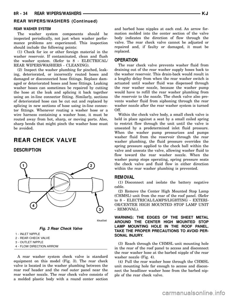
A rear washer system check valve is standard
equipment on this model (Fig. 3). The rear check
valve is located in the washer plumbing between the
rear roof header and the roof outer panel near the
rear washer nozzle. The rear check valve consists of
a molded plastic body with a round center sectionand barbed hose nipples at each end. An arrow for-
mation molded into the center section of the valve
body indicates the direction of flow through the
valve. The rear check valve cannot be adjusted or
repaired and, if faulty or damaged, it must be
replaced.
OPERATION
The rear check valve prevents washer fluid from
draining out of the rear washer supply hoses back to
the washer reservoir. This drain-back would result in
a lengthy delay from when the rear washer switch is
actuated until washer fluid was dispensed through
the rear washer nozzle, because the washer pump
would have to refill the rear washer plumbing from
the reservoir to the nozzle. The check valve also pre-
vents washer fluid from siphoning through the rear
washer nozzle after the rear washer system is turned
Off.
Within the check valve body, a small check valve is
held in place against a seat by a small coiled spring
to restrict flow through the unit until the valve is
unseated by a predetermined inlet fluid pressure.
When the washer pump pressurizes and pumps
washer fluid from the reservoir through the rear
washer plumbing, the fluid pressure overrides the
spring pressure applied to the check ball within the
valve and unseats the valve, allowing washer fluid to
flow toward the rear washer nozzle. When the
washer pump stops operating, spring pressure seats
the check valve and fluid flow in either direction
within the rear washer plumbing is prevented.
REMOVAL
(1) Disconnect and isolate the battery negative
cable.
(2) Remove the Center High Mounted Stop Lamp
(CHMSL) unit from the rear of the roof panel. (Refer
to 8 - ELECTRICAL/LAMPS/LIGHTING - EXTERI-
OR/CENTER HIGH MOUNTED STOP LAMP UNIT
- REMOVAL).
WARNING: THE EDGES OF THE SHEET METAL
AROUND THE CENTER HIGH MOUNTED STOP
LAMP MOUNTING HOLE IN THE ROOF PANEL.
TAKE THE PROPER PRECAUTIONS TO AVOID PER-
SONAL INJURY.
(3) Reach through the CHMSL unit mounting hole
in the rear of the roof panel to access and disconnect
the rear washer hose at the barbed nipple of the rear
washer nozzle (Fig. 4).
(4) Pull the rear washer hose through the CHMSL
unit mounting hole far enough to access and discon-
nect the headliner washer hose from the barbed nip-
ple of the rear check valve.
Fig. 3 Rear Check Valve
1 - INLET NIPPLE
2 - REAR CHECK VALVE
3 - OUTLET NIPPLE
4 - FLOW DIRECTION ARROW
8R - 34 REAR WIPERS/WASHERSKJ
REAR WIPERS/WASHERS (Continued)
Page 1283 of 1803

INTAKE MANIFOLD
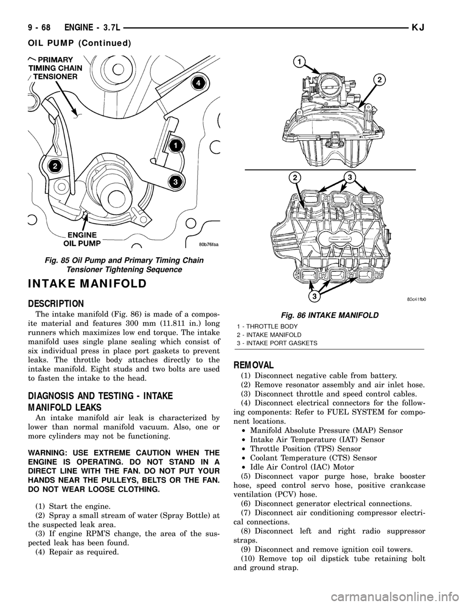
DESCRIPTION
The intake manifold (Fig. 86) is made of a compos-
ite material and features 300 mm (11.811 in.) long
runners which maximizes low end torque. The intake
manifold uses single plane sealing which consist of
six individual press in place port gaskets to prevent
leaks. The throttle body attaches directly to the
intake manifold. Eight studs and two bolts are used
to fasten the intake to the head.
DIAGNOSIS AND TESTING - INTAKE
MANIFOLD LEAKS
An intake manifold air leak is characterized by
lower than normal manifold vacuum. Also, one or
more cylinders may not be functioning.
WARNING: USE EXTREME CAUTION WHEN THE
ENGINE IS OPERATING. DO NOT STAND IN A
DIRECT LINE WITH THE FAN. DO NOT PUT YOUR
HANDS NEAR THE PULLEYS, BELTS OR THE FAN.
DO NOT WEAR LOOSE CLOTHING.
(1) Start the engine.
(2) Spray a small stream of water (Spray Bottle) at
the suspected leak area.
(3) If engine RPM'S change, the area of the sus-
pected leak has been found.
(4) Repair as required.
REMOVAL
(1) Disconnect negative cable from battery.
(2) Remove resonator assembly and air inlet hose.
(3) Disconnect throttle and speed control cables.
(4) Disconnect electrical connectors for the follow-
ing components: Refer to FUEL SYSTEM for compo-
nent locations.
²Manifold Absolute Pressure (MAP) Sensor
²Intake Air Temperature (IAT) Sensor
²Throttle Position (TPS) Sensor
²Coolant Temperature (CTS) Sensor
²Idle Air Control (IAC) Motor
(5) Disconnect vapor purge hose, brake booster
hose, speed control servo hose, positive crankcase
ventilation (PCV) hose.
(6) Disconnect generator electrical connections.
(7) Disconnect air conditioning compressor electri-
cal connections.
(8) Disconnect left and right radio suppressor
straps.
(9) Disconnect and remove ignition coil towers.
(10) Remove top oil dipstick tube retaining bolt
and ground strap.
Fig. 85 Oil Pump and Primary Timing Chain
Tensioner Tightening Sequence
Fig. 86 INTAKE MANIFOLD
1 - THROTTLE BODY
2 - INTAKE MANIFOLD
3 - INTAKE PORT GASKETS
9 - 68 ENGINE - 3.7LKJ
OIL PUMP (Continued)
Page 1737 of 1803

OPERATION
The PCV system operates by engine intake mani-
fold vacuum. Filtered air is routed into the crankcase
through the air cleaner hose and crankcase breath-
er(s) (if used). The metered air, along with crankcase
vapors, are drawn through the PCV valve and into a
passage in the intake manifold. The PCV system
manages crankcase pressure and meters blow-by
gases to the intake system, reducing engine sludge
formation.
The PCV valve contains a spring loaded plunger.
This plunger meters the amount of crankcase vapors
routed into the combustion chamber based on intake
manifold vacuum.
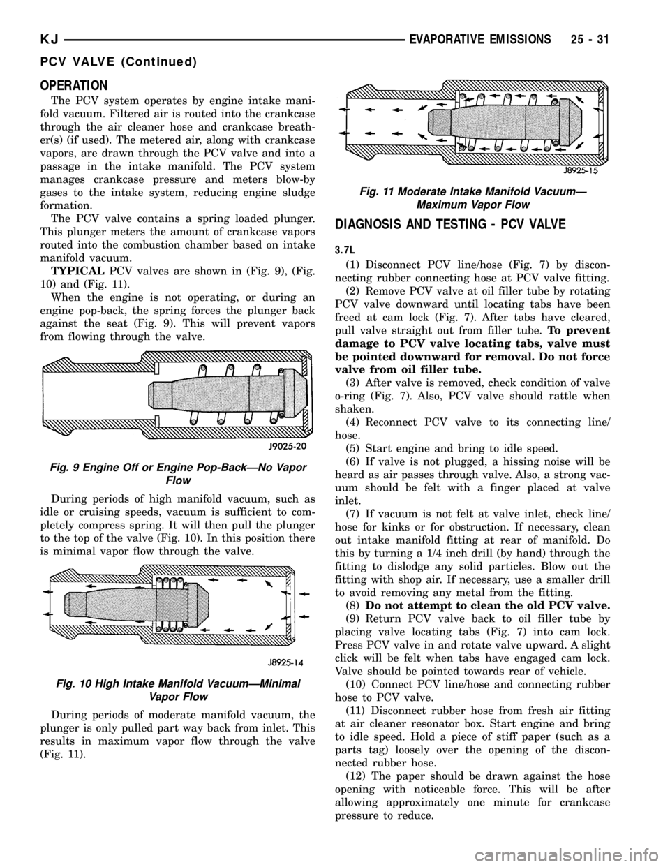
TYPICALPCV valves are shown in (Fig. 9), (Fig.
10) and (Fig. 11).
When the engine is not operating, or during an
engine pop-back, the spring forces the plunger back
against the seat (Fig. 9). This will prevent vapors
from flowing through the valve.
During periods of high manifold vacuum, such as
idle or cruising speeds, vacuum is sufficient to com-
pletely compress spring. It will then pull the plunger
to the top of the valve (Fig. 10). In this position there
is minimal vapor flow through the valve.
During periods of moderate manifold vacuum, the
plunger is only pulled part way back from inlet. This
results in maximum vapor flow through the valve
(Fig. 11).
DIAGNOSIS AND TESTING - PCV VALVE
3.7L
(1) Disconnect PCV line/hose (Fig. 7) by discon-
necting rubber connecting hose at PCV valve fitting.
(2) Remove PCV valve at oil filler tube by rotating
PCV valve downward until locating tabs have been
freed at cam lock (Fig. 7). After tabs have cleared,
pull valve straight out from filler tube.To prevent
damage to PCV valve locating tabs, valve must
be pointed downward for removal. Do not force
valve from oil filler tube.
(3) After valve is removed, check condition of valve
o-ring (Fig. 7). Also, PCV valve should rattle when
shaken.
(4) Reconnect PCV valve to its connecting line/
hose.
(5) Start engine and bring to idle speed.
(6) If valve is not plugged, a hissing noise will be
heard as air passes through valve. Also, a strong vac-
uum should be felt with a finger placed at valve
inlet.
(7) If vacuum is not felt at valve inlet, check line/
hose for kinks or for obstruction. If necessary, clean
out intake manifold fitting at rear of manifold. Do
this by turning a 1/4 inch drill (by hand) through the
fitting to dislodge any solid particles. Blow out the
fitting with shop air. If necessary, use a smaller drill
to avoid removing any metal from the fitting.
(8)Do not attempt to clean the old PCV valve.
(9) Return PCV valve back to oil filler tube by
placing valve locating tabs (Fig. 7) into cam lock.
Press PCV valve in and rotate valve upward. A slight
click will be felt when tabs have engaged cam lock.
Valve should be pointed towards rear of vehicle.
(10) Connect PCV line/hose and connecting rubber
hose to PCV valve.
(11) Disconnect rubber hose from fresh air fitting
at air cleaner resonator box. Start engine and bring
to idle speed. Hold a piece of stiff paper (such as a
parts tag) loosely over the opening of the discon-
nected rubber hose.
(12) The paper should be drawn against the hose
opening with noticeable force. This will be after
allowing approximately one minute for crankcase
pressure to reduce.
Fig. 9 Engine Off or Engine Pop-BackÐNo Vapor
Flow
Fig. 10 High Intake Manifold VacuumÐMinimal
Vapor Flow
Fig. 11 Moderate Intake Manifold VacuumÐ
Maximum Vapor Flow
KJEVAPORATIVE EMISSIONS 25 - 31
PCV VALVE (Continued)