2002 JEEP LIBERTY light
[x] Cancel search: lightPage 96 of 1803

(5) Apply a light coating of gear lubricant on the
lip of pinion seal and intall seal with an appropriate
installer (Fig. 55).
(6) Install rear pinion bearing and oil slinger/depth
shim onto the pinion shaft with Installer 6448 and a
press (Fig. 56).(7) Install anewcollapsible spacer on pinion shaft
and install the pinion into the housing (Fig. 57).
(8) Install pinion companion flange, with Installer
W-162-D, Cup 8109 and Spanner Wrench 6958.
(9) Install pinion anewnut onto the pinion gear
and tighten the nut to 216 N´m (160 ft. lbs.).Do not
over-tighten.
CAUTION: Never loosen pinion gear nut to decrease
pinion rotating torque and never exceed specified
preload torque. If preload torque is exceeded a new
collapsible spacer must be installed.
Fig. 55 PINION SEAL
1 - HANDLE
2 - INSTALLER
Fig. 56 REAR PINION BEARING
1 - INSTALLER
2 - OIL SLINGER
3 - PINION GEAR
4 - REAR PINION BEARING
5 - PRESS
Fig. 57 COLLAPSIBLE PRELOAD SPACER
1 - COLLAPSIBLE SPACER
2 - SHOULDER
3 - PINION GEAR
4 - OIL SLINGER
5 - REAR BEARING
KJFRONT AXLE - 186FIA 3 - 47
PINION GEAR/RING GEAR (Continued)
Page 100 of 1803

The Trac-lokŸ design provides the differential
action needed for turning corners and for driving
straight ahead during periods of unequal traction.
When one wheel looses traction, the clutch packs
transfer additional torque to the wheel having the
most traction. Trac-lokŸ differentials resist wheel
spin on bumpy roads and provide more pulling power
when one wheel looses traction. Pulling power is pro-
vided continuously until both wheels loose traction. If
both wheels slip due to unequal traction, Trac-lokŸ
operation is normal. In extreme cases of differences
of traction, the wheel with the least traction may
spin.
DIAGNOSIS AND TESTING - AXLE
GEAR NOISE
Axle gear noise can be caused by insufficient lubri-
cant, incorrect backlash, incorrect pinion depth, tooth
contact, worn/damaged gears, or the carrier housing
not having the proper offset and squareness.
Gear noise usually happens at a specific speed
range. The noise can also occur during a specific type
of driving condition. These conditions are accelera-
tion, deceleration, coast, or constant load.
When road testing, first warm-up the axle fluid by
driving the vehicle at least 5 miles and then acceler-
ate the vehicle to the speed range where the noise is
the greatest. Shift out-of-gear and coast through the
peak-noise range. If the noise stops or changes
greatly:
²Check for insufficient lubricant.
²Incorrect ring gear backlash.
²Gear damage.
Differential side gears and pinions can be checked
by turning the vehicle. They usually do not cause
noise during straight-ahead driving when the gears
are unloaded. The side gears are loaded during vehi-
cle turns. A worn pinion shaft can also cause a snap-
ping or a knocking noise.
BEARING NOISE
The axle shaft, differential and pinion bearings can
all produce noise when worn or damaged. Bearing
noise can be either a whining, or a growling sound.
Pinion bearings have a constant-pitch noise. This
noise changes only with vehicle speed. Pinion bearing
noise will be higher pitched because it rotates at a
faster rate. Drive the vehicle and load the differen-
tial. If bearing noise occurs, the rear pinion bearing
is the source of the noise. If the bearing noise is
heard during a coast, the front pinion bearing is the
source.
Worn or damaged differential bearings usually pro-
duce a low pitch noise. Differential bearing noise is
similar to pinion bearing noise. The pitch of differen-tial bearing noise is also constant and varies only
with vehicle speed.
Axle shaft bearings produce noise and vibration
when worn or damaged. The noise generally changes
when the bearings are loaded. Road test the vehicle.
Turn the vehicle sharply to the left and to the right.
This will load the bearings and change the noise
level. Where axle bearing damage is slight, the noise
is usually not noticeable at speeds above 30 mph.
LOW SPEED KNOCK
Low speed knock is generally caused by a worn
U-joint or by worn side±gear thrust washers. A worn
pinion shaft bore will also cause low speed knock.
VIBRATION
Vibration at the rear of the vehicle is usually
caused by a:
²Damaged drive shaft.
²Missing drive shaft balance weight(s).
²Worn or out-of-balance wheels.
²Loose wheel lug nuts.
²Worn U-joint(s).
²Loose/broken springs.
²Damaged axle shaft bearing(s).
²Loose pinion gear nut.
²Excessive pinion yoke run out.
²Bent axle shaft(s).
Check for loose or damaged front-end components
or engine/transmission mounts. These components
can contribute to what appears to be a rearend vibra-
tion. Do not overlook engine accessories, brackets
and drive belts.
NOTE: All driveline components should be exam-
ined before starting any repair.
DRIVELINE SNAP
A snap or clunk noise when the vehicle is shifted
into gear (or the clutch engaged), can be caused by:
²High engine idle speed.
²Transmission shift operation.
²Loose engine/transmission/transfer case mounts.
²Worn U-joints.
²Loose spring mounts.
²Loose pinion gear nut and yoke.
²Excessive ring gear backlash.
²Excessive side gear to case clearance.
The source of a snap or a clunk noise can be deter-
mined with the assistance of a helper. Raise the vehi-
cle on a hoist with the wheels free to rotate. Instruct
the helper to shift the transmission into gear. Listen
for the noise, a mechanics stethoscope is helpful in
isolating the source of a noise.
KJREAR AXLE - 198RBI 3 - 51
REAR AXLE - 198RBI (Continued)
Page 117 of 1803

PINION SEAL
REMOVAL
(1) Raise and support the vehicle.
(2) Remove wheel and tire assemblies.
(3) Remove rear brake rotors drums.
(4) Mark propeller shaft and pinion yoke for
installation reference.
(5) Remove the propeller shaft from the yoke.
(6) Rotate pinion gear three or four times and ver-
ify that pinion rotates smoothly.
(7) Measure and record torque to rotate the pinion
gear with an inch pound dial-type torque wrench.
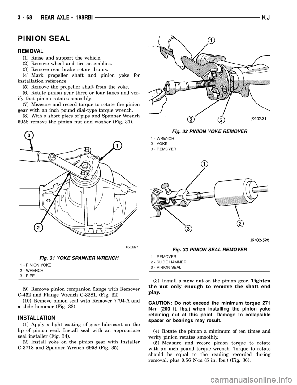
(8) With a short piece of pipe and Spanner Wrench
6958 remove the pinion nut and washer (Fig. 31).
(9) Remove pinion companion flange with Remover
C-452 and Flange Wrench C-3281. (Fig. 32)
(10) Remove pinion seal with Remover 7794-A and
a slide hammer (Fig. 33).
INSTALLATION
(1) Apply a light coating of gear lubricant on the
lip of pinion seal. Install seal with an appropriate
seal installer (Fig. 34).
(2) Install yoke on the pinion gear with Installer
C-3718 and Spanner Wrench 6958 (Fig. 35).(3) Install anewnut on the pinion gear.Tighten
the nut only enough to remove the shaft end
play.
CAUTION: Do not exceed the minimum torque 271
N´m (200 ft. lbs.) when installing the pinion yoke
retaining nut at this point. Damage to collapsible
spacer or bearings may result.
(4) Rotate the pinion a minimum of ten times and
verify pinion rotates smoothly.
(5) Measure and recore pinion torque to rotate
with an inch pound torque wrench. Torque to rotate
should be equal to the reading recorded during
removal, plus 0.56 N´m (5 in. lbs.) (Fig. 36).
Fig. 31 YOKE SPANNER WRENCH
1 - PINION YOKE
2 - WRENCH
3 - PIPE
Fig. 32 PINION YOKE REMOVER
1 - WRENCH
2 - YOKE
3 - REMOVER
Fig. 33 PINION SEAL REMOVER
1 - REMOVER
2 - SLIDE HAMMER
3 - PINION SEAL
3 - 68 REAR AXLE - 198RBIKJ
Page 119 of 1803

(8) Fill differential with gear lubricant.
(9) Install the brake drums
(10) Install wheel and tire assemblies.
(11) Lower the vehicle.
COLLAPSIBLE SPACER
REMOVAL
(1) Raise and support the vehicle.
(2) Remove wheel and tire assemblies.
(3) Remove rear brake drums.
(4) Mark the propeller shaft and pinion yoke for
installation reference.
(5) Remove the propeller shaft from the yoke.
(6) Rotate the pinion gear three or four times.
(7) Measure and record torque to rotate the pinion
gear with an inch pound dial-type torque wrench.
(8) Hold pinion yoke with Spanner Wrench 6958
and remove pinion nut and washer.
(9) Remove the pinion yoke with Remover C-452
and Flange Wrench C-3281 (Fig. 38).
(10) Remove pinion shaft seal with a pry tool or a
slide hammer mounted screw.
(11) Remove front pinion bearing using a pair of
pick tools. Pull the bearing straight off the pinion
gear shaft. If the bearing becomes bound on the pin-
ion shaft, lightly tap the end of the pinion gear with
a rawhide/rubber hammer.
(12) Remove the collapsible spacer.
INSTALLATION
(1) Install anewcollapsible preload spacer on pin-
ion shaft.
(2) Install pinion front bearing.(3) Apply a light coating of gear lubricant on the
lip of pinion seal and install anewseal with an
appropriate installer (Fig. 39).
(4) Install yoke with Screw 8112, Cup 8109 and
Spanner Wrench 6958 (Fig. 40).
(5) Install yoke washer andnewnut on the pinion
gear. Tighten the nut to 271 N´m (200 ft. lbs.).
CAUTION: Never loosen pinion gear nut to decrease
pinion gear bearing rotating torque and never
exceed specified preload torque. If preload torque
or rotating torque is exceeded a new collapsible
spacer must be installed.
Fig. 38 PINION YOKE
1 - FLANGE WRENCH
2 - YOKE
3 - REMOVER
Fig. 39 PINION SEAL
1 - HANDLE
2 - INSTALLER
Fig. 40 PINION YOKE INSTALLER
1 - INSTALLER
2 - PINION YOKE
3 - WRENCH
3 - 70 REAR AXLE - 198RBIKJ
PINION SEAL (Continued)
Page 120 of 1803

(6) Using yoke with Spanner Wrench 6958 and a
torque wrench set at 474 N´m (350 ft. lbs.), (Fig. 41)
slowly tighten the nut in 6.8 N´m (5 ft. lbs.) incre-
ments until the rotating torque is achieved. Measure
the rotating torque frequently to avoid over crushing
the collapsible spacer (Fig. 42).
NOTE: If more than 474 N´m (350 ft. lbs.) torque is
required to crush the collapsible spacer, the spacer
is defective and must be replaced.
(7) Check rotating torque with an inch pound
torque wrench (Fig. 42). The rotating torque of the
pinion gear should be, the reading recorded during
removal plus an additional 0.56 N´m (5 in. lbs.).
(8) Install propeller shaft with reference marks
aligned.
(9) Install rear brake drums.
(10) Add gear lubricant, if necessary.
(11) Install wheel and tire assemblies.
(12) Remove supports and lower vehicle.
DIFFERENTIAL
REMOVAL
(1) Raise and support vehicle.
(2) Remove differential cover and drain fluid.
(3) Clean the housing cavity with flushing oil, light
engine oil or lint free cloth.NOTE: Do not use water, steam, kerosene or gaso-
line for cleaning.
(4) Remove axle shafts.
(5)
Note the reference letters stamped on the bearing
caps and housing machined sealing surface (Fig. 43).
Fig. 41 YOKE SPANNER WRENCH
1 - PINION YOKE
2 - WRENCH
3 - PIPE
Fig. 42 PINION ROTATING TORQUE
1 - TORQUE WRENCH
2 - PINION YOKE
Fig. 43 BEARING CAP IDENTIFICATION
1 - REFERENCE LETTERS
2 - REFERENCE LETTERS
KJREAR AXLE - 198RBI 3 - 71
COLLAPSIBLE SPACER (Continued)
Page 127 of 1803

(3) Position assembled clutch disc packs on the
side gear hubs.
(4) Install clutch pack and side gear in the ring
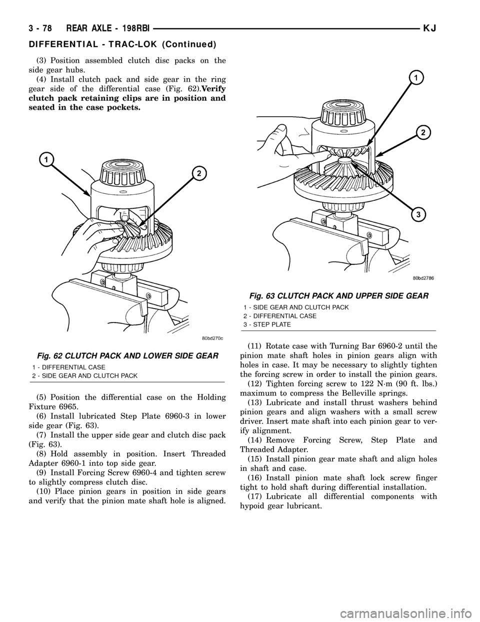
gear side of the differential case (Fig. 62).Verify
clutch pack retaining clips are in position and
seated in the case pockets.
(5) Position the differential case on the Holding
Fixture 6965.
(6) Install lubricated Step Plate 6960-3 in lower
side gear (Fig. 63).
(7) Install the upper side gear and clutch disc pack
(Fig. 63).
(8) Hold assembly in position. Insert Threaded
Adapter 6960-1 into top side gear.
(9) Install Forcing Screw 6960-4 and tighten screw
to slightly compress clutch disc.
(10) Place pinion gears in position in side gears
and verify that the pinion mate shaft hole is aligned.(11) Rotate case with Turning Bar 6960-2 until the
pinion mate shaft holes in pinion gears align with
holes in case. It may be necessary to slightly tighten
the forcing screw in order to install the pinion gears.
(12) Tighten forcing screw to 122 N´m (90 ft. lbs.)
maximum to compress the Belleville springs.
(13) Lubricate and install thrust washers behind
pinion gears and align washers with a small screw
driver. Insert mate shaft into each pinion gear to ver-
ify alignment.
(14) Remove Forcing Screw, Step Plate and
Threaded Adapter.
(15) Install pinion gear mate shaft and align holes
in shaft and case.
(16) Install pinion mate shaft lock screw finger
tight to hold shaft during differential installation.
(17) Lubricate all differential components with
hypoid gear lubricant.
Fig. 62 CLUTCH PACK AND LOWER SIDE GEAR
1 - DIFFERENTIAL CASE
2 - SIDE GEAR AND CLUTCH PACK
Fig. 63 CLUTCH PACK AND UPPER SIDE GEAR
1 - SIDE GEAR AND CLUTCH PACK
2 - DIFFERENTIAL CASE
3 - STEP PLATE
3 - 78 REAR AXLE - 198RBIKJ
DIFFERENTIAL - TRAC-LOK (Continued)
Page 132 of 1803

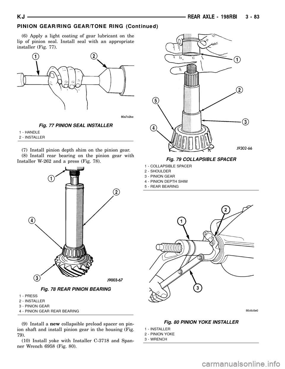
(6) Apply a light coating of gear lubricant on the
lip of pinion seal. Install seal with an appropriate
installer (Fig. 77).
(7) Install pinion depth shim on the pinion gear.
(8) Install rear bearing on the pinion gear with
Installer W-262 and a press (Fig. 78).
(9) Install anewcollapsible preload spacer on pin-
ion shaft and install pinion gear in the housing (Fig.
79).
(10) Install yoke with Installer C-3718 and Span-
ner Wrench 6958 (Fig. 80).
Fig. 77 PINION SEAL INSTALLER
1 - HANDLE
2 - INSTALLER
Fig. 78 REAR PINION BEARING
1 - PRESS
2 - INSTALLER
3 - PINION GEAR
4 - PINION GEAR REAR BEARING
Fig. 79 COLLAPSIBLE SPACER
1 - COLLAPSIBLE SPACER
2 - SHOULDER
3 - PINION GEAR
4 - PINION DEPTH SHIM
5 - REAR BEARING
Fig. 80 PINION YOKE INSTALLER
1 - INSTALLER
2 - PINION YOKE
3 - WRENCH
KJREAR AXLE - 198RBI 3 - 83
PINION GEAR/RING GEAR/TONE RING (Continued)
Page 137 of 1803

traction. Pulling power is provided continuously until
both wheels loose traction. If both wheels slip due to
unequal traction, Trac-lokŸ operation is normal. In
extreme cases of differences of traction, the wheel
with the least traction may spin.
DIAGNOSIS AND TESTING - AXLE
GEAR NOISE
Axle gear noise can be caused by insufficient lubri-
cant, incorrect backlash, incorrect pinion depth, tooth
contact, worn/damaged gears, or the carrier housing
not having the proper offset and squareness.
Gear noise usually happens at a specific speed
range. The noise can also occur during a specific type
of driving condition. These conditions are accelera-
tion, deceleration, coast, or constant load.
When road testing, first warm-up the axle fluid by
driving the vehicle at least 5 miles and then acceler-
ate the vehicle to the speed range where the noise is
the greatest. Shift out-of-gear and coast through the
peak-noise range. If the noise stops or changes
greatly:
²Check for insufficient lubricant.
²Incorrect ring gear backlash.
²Gear damage.
Differential side gears and pinions can be checked
by turning the vehicle. They usually do not cause
noise during straight-ahead driving when the gears
are unloaded. The side gears are loaded during vehi-
cle turns. A worn pinion shaft can also cause a snap-
ping or a knocking noise.
BEARING NOISE
The axle shaft, differential and pinion bearings can
all produce noise when worn or damaged. Bearing
noise can be either a whining, or a growling sound.
Pinion bearings have a constant-pitch noise. This
noise changes only with vehicle speed. Pinion bearing
noise will be higher pitched because it rotates at a
faster rate. Drive the vehicle and load the differen-
tial. If bearing noise occurs, the rear pinion bearing
is the source of the noise. If the bearing noise is
heard during a coast, the front pinion bearing is the
source.
Worn or damaged differential bearings usually pro-
duce a low pitch noise. Differential bearing noise is
similar to pinion bearing noise. The pitch of differen-
tial bearing noise is also constant and varies only
with vehicle speed.
Axle shaft bearings produce noise and vibration
when worn or damaged. The noise generally changeswhen the bearings are loaded. Road test the vehicle.
Turn the vehicle sharply to the left and to the right.
This will load the bearings and change the noise
level. Where axle bearing damage is slight, the noise
is usually not noticeable at speeds above 30 mph.
LOW SPEED KNOCK
Low speed knock is generally caused by a worn
U-joint or by worn side±gear thrust washers. A worn
pinion shaft bore will also cause low speed knock.
VIBRATION
Vibration at the rear of the vehicle is usually
caused by a:
²Damaged drive shaft.
²Missing drive shaft balance weight(s).
²Worn or out-of-balance wheels.
²Loose wheel lug nuts.
²Worn U-joint(s).
²Loose/broken springs.
²Damaged axle shaft bearing(s).
²Loose pinion gear nut.
²Excessive pinion yoke run out.
²Bent axle shaft(s).
Check for loose or damaged front-end components
or engine/transmission mounts. These components
can contribute to what appears to be a rearend vibra-
tion. Do not overlook engine accessories, brackets
and drive belts.
NOTE: All driveline components should be exam-
ined before starting any repair.
DRIVELINE SNAP
A snap or clunk noise when the vehicle is shifted
into gear (or the clutch engaged), can be caused by:
²High engine idle speed.
²Transmission shift operation.
²Loose engine/transmission/transfer case mounts.
²Worn U-joints.
²Loose spring mounts.
²Loose pinion gear nut and yoke.
²Excessive ring gear backlash.
²Excessive side gear to case clearance.
The source of a snap or a clunk noise can be deter-
mined with the assistance of a helper. Raise the vehi-
cle on a hoist with the wheels free to rotate. Instruct
the helper to shift the transmission into gear. Listen
for the noise, a mechanics stethoscope is helpful in
isolating the source of a noise.
3 - 88 REAR AXLE-81/4KJ
REAR AXLE - 8 1/4 (Continued)