2002 JEEP LIBERTY flat tire
[x] Cancel search: flat tirePage 483 of 1803

enough to disengage the locator tab on the outboard
side of the unit (Fig. 41) or (Fig. 42) from the engage-
ment slot in the outboard edge of the reinforcement.
(5) Pull the headlamp unit away from the grille
opening reinforcement far enough to disconnect the
wire harness connectors from the headlamp bulbsocket (North America), the headlamp bulb base
(Rest-Of-World), the front position lamp socket (if
equipped), and the headlamp leveling motor (if
equipped).
(6) Remove the headlamp unit from the grille
opening reinforcement.
INSTALLATION
(1) Position the headlamp unit to the grille open-
ing reinforcement.
(2) Reconnect the wire harness connectors to the
headlamp bulb socket (North America), the headlamp
bulb base (Rest-Of-World), the front position lamp
socket (if equipped), and the headlamp leveling motor
(if equipped) (Fig. 41) or (Fig. 42).
(3) Engage the locator tab on the outboard side of
the headlamp unit into the engagement slot in the
outboard edge of the grille opening reinforcement.
(4) Align the two mounting tabs on the inboard
side of the headlamp unit housing to the mounting
holes in the grille opening reinforcement (Fig. 40).
(5) Install and tighten the two screws that secure
the mounting tabs on the inboard side of the head-
lamp unit housing to the grille opening reinforce-
ment. Tighten the screws to 3 N´m (30 in. lbs.).
(6) Reinstall the grille panel onto the grille open-
ing reinforcement. (Refer to 23 - BODY/EXTERIOR/
GRILLE - INSTALLATION).
(7) Reconnect the battery negative cable.
(8) Confirm proper headlamp unit alignment.
(Refer to 8 - ELECTRICAL/LAMPS/LIGHTING -
EXTERIOR/HEADLAMP UNIT - ADJUSTMENTS).
ADJUSTMENTS
ADJUSTMENT - HEADLAMP UNIT
VEHICLE PREPARATION FOR HEADLAMP ALIGNMENT
(1) Verify headlamp dimmer (multi-function)
switch and high beam indicator operation.
(2) If the vehicle is equipped with headlamp level-
ing, be certain that the headlamp leveling switch is
in the ª0º position.
(3) Repair or replace any faulty or damaged com-
ponents that could hinder proper lamp alignment.
(4) Verify proper tire inflation.
(5) Clean headlamp lenses.
(6) Verify that cargo area is not heavily loaded.
(7) The fuel tank should be Full. Add 2.94 kilo-
grams (6.5 pounds) of weight over the fuel tank for
each estimated gallon of missing fuel.
HEADLAMP ALIGNMENT SCREEN PREPARATION
Prepare an alignment screen as illustrated.
(1) Position the vehicle on a level surface perpen-
dicular to a flat wall 7.62 meters (25 feet) away from
Fig. 41 Headlamp Unit - North America
1 - MOUNTING TAB (2)
2 - ADJUSTING SCREW
3 - LOCK RING
4 - HOUSING
5 - LOCATOR TAB
6 - SOCKET & BULB
Fig. 42 Headlamp Unit - Rest-Of-World
1 - LEVELING MOTOR (IF EQUIPPED)
2 - BOOT SEAL
3 - ADJUSTING SCREW
4 - LOCATOR TAB
5 - HOUSING
6 - FRONT POSITION LAMP SOCKET & BULB
7 - HEADLAMP BULB
8 - MOUNTING TAB (2)
8L - 42 LAMPS/LIGHTING - EXTERIORKJ
HEADLAMP UNIT (Continued)
Page 550 of 1803

(5) From the front of the vehicle, pull the front fog
lamp unit out of the front bumper fascia far enough
to access and disconnect the wire harness connector
for the front fog lamp unit from the lamp socket con-
nector receptacle (Fig. 15).
(6) Remove the front fog lamp unit from the front
bumper fascia.
INSTALLATION
(1) Position the front fog lamp unit to the front
bumper fascia.
(2) Reconnect the wire harness connector for the
front fog lamp to the lamp socket connector recepta-
cle (Fig. 15).
(3) Position the front fog lamp unit into the front
bumper fascia.
(4) Reach into the front wheel opening and
through the access hole to install and tighten the
three screws that secure the front fog lamp unit
housing to the front bumper fascia (Fig. 14). Tighten
the screws to 3 N´m (25 in. lbs.).
(5) Lower and snap shut the cover over the access
hole at the front of the front wheelhouse splash
shield.
(6) Reconnect the battery negative cable.
(7) Confirm proper front fog lamp unit alignment.
(Refer to 8 - ELECTRICAL/LAMPS/LIGHTING -
EXTERIOR/FRONT FOG LAMP UNIT - ADJUST-
MENTS).
ADJUSTMENTS
ADJUSTMENT - FRONT FOG LAMP UNIT
VEHICLE PREPARATION FOR FOG LAMP ALIGNMENT
(1) Repair or replace any faulty or damaged com-
ponents that could hinder proper lamp alignment.
(2) Verify proper tire inflation.
(3) Clean the front fog lamp lenses.
(4) Verify that the cargo area is not heavily loaded.
(5) The fuel tank should be Full. Add 2.94 kilo-
grams (6.5 pounds) of weight over the fuel tank for
each estimated gallon of missing fuel.
FOG LAMP ALIGNMENT
Prepare an alignment screen as illustrated. A prop-
erly aligned front fog lamp will project a pattern on
the alignment screen 100 millimeters (4 inches)
below the fog lamp centerline and straight ahead of
the lamp.
(1) Position the vehicle on a level surface perpen-
dicular to a flat wall 7.62 meters (25 feet) away from
the front of the front fog lamp lens (Fig. 16). If nec-
essary, tape a line on the floor 7.62 meters (25 feet)
away from and parallel to the wall.
(2) Measure up on the wall 1.27 meters (5 feet)
from the floor and tape a vertical line on the align-
ment screen at the centerline of the vehicle. Sight
along the centerline of the vehicle (from the rear of
the vehicle forward) to verify the accuracy of the cen-
terline placement.
Fig. 14 Front Fog Lamp Unit Remove/Install
1 - FRONT FOG LAMP UNIT
2 - SCREW (3)
3 - FRONT WHEELHOUSE SPLASH SHIELD
4 - FRONT BUMPER FASCIA
5 - ACCESS HOLE
Fig. 15 Front Fog Lamp Unit
1 - ADJUSTING SCREW
2 - MOUNTING BRACKET
3 - HOUSING
4 - SOCKET & BULB
5 - LENS
KJLAMPS8Ls-25
FRONT FOG LAMP UNIT (Continued)
Page 567 of 1803

(4) Pull the inboard side of the headlamp unit
away from the grille opening reinforcement far
enough to disengage the locator tab on the outboard
side of the unit (Fig. 41) or (Fig. 42) from the engage-
ment slot in the outboard edge of the reinforcement.(5) Pull the headlamp unit away from the grille
opening reinforcement far enough to disconnect the
wire harness connectors from the headlamp bulb
socket (North America), the headlamp bulb base
(Rest-Of-World), the front position lamp socket (if
equipped), and the headlamp leveling motor (if
equipped).
(6) Remove the headlamp unit from the grille
opening reinforcement.
INSTALLATION
(1) Position the headlamp unit to the grille open-
ing reinforcement.
(2) Reconnect the wire harness connectors to the
headlamp bulb socket (North America), the headlamp
bulb base (Rest-Of-World), the front position lamp
socket (if equipped), and the headlamp leveling motor
(if equipped) (Fig. 41) or (Fig. 42).
(3) Engage the locator tab on the outboard side of
the headlamp unit into the engagement slot in the
outboard edge of the grille opening reinforcement.
(4) Align the two mounting tabs on the inboard
side of the headlamp unit housing to the mounting
holes in the grille opening reinforcement (Fig. 40).
(5) Install and tighten the two screws that secure
the mounting tabs on the inboard side of the head-
lamp unit housing to the grille opening reinforce-
ment. Tighten the screws to 3 N´m (30 in. lbs.).
(6) Reinstall the grille panel onto the grille open-
ing reinforcement. (Refer to 23 - BODY/EXTERIOR/
GRILLE - INSTALLATION).
(7) Reconnect the battery negative cable.
(8) Confirm proper headlamp unit alignment.
(Refer to 8 - ELECTRICAL/LAMPS/LIGHTING -
EXTERIOR/HEADLAMP UNIT - ADJUSTMENTS).
ADJUSTMENTS
ADJUSTMENT - HEADLAMP UNIT
VEHICLE PREPARATION FOR HEADLAMP ALIGNMENT
(1) Verify headlamp dimmer (multi-function)
switch and high beam indicator operation.
(2) If the vehicle is equipped with headlamp level-
ing, be certain that the headlamp leveling switch is
in the ª0º position.
(3) Repair or replace any faulty or damaged com-
ponents that could hinder proper lamp alignment.
(4) Verify proper tire inflation.
(5) Clean headlamp lenses.
(6) Verify that cargo area is not heavily loaded.
(7) The fuel tank should be Full. Add 2.94 kilo-
grams (6.5 pounds) of weight over the fuel tank for
each estimated gallon of missing fuel.
Fig. 41 Headlamp Unit - North America
1 - MOUNTING TAB (2)
2 - ADJUSTING SCREW
3 - LOCK RING
4 - HOUSING
5 - LOCATOR TAB
6 - SOCKET & BULB
Fig. 42 Headlamp Unit - Rest-Of-World
1 - LEVELING MOTOR (IF EQUIPPED)
2 - BOOT SEAL
3 - ADJUSTING SCREW
4 - LOCATOR TAB
5 - HOUSING
6 - FRONT POSITION LAMP SOCKET & BULB
7 - HEADLAMP BULB
8 - MOUNTING TAB (2)
8Ls - 42 LAMPSKJ
HEADLAMP UNIT (Continued)
Page 632 of 1803

Typically, the vehicle occupants recall more about
the events preceding and following a collision than
they have of an airbag deployment itself. This is
because the airbag deployment and deflation occur so
rapidly. In a typical 48 kilometer-per-hour (30 mile-
per-hour) barrier impact, from the moment of impact
until the airbags are fully inflated takes about 40
milliseconds. Within one to two seconds from the
moment of impact, the airbags are almost entirely
deflated. The times cited for these events are approx-
imations, which apply only to a barrier impact at the
given speed. Actual times will vary somewhat,
depending upon the vehicle speed, impact angle,
severity of the impact, and the type of collision.
When the ACM monitors a problem in any of the
dual front airbag system circuits or components,
including the seat belt tensioner, it stores a fault
code or Diagnostic Trouble Code (DTC) in its memory
circuit and sends an electronic message to the EMIC
to turn on the airbag indicator. When the SIACM
monitors a problem in any of the side curtain airbag
system circuits or component, it stores a fault code or
Diagnostic Trouble Code (DTC) in its memory circuit
and sends an electronic message to the ACM, and the
ACM sends an electronic message to the EMIC to
turn on the airbag indicator. Proper testing of the
airbag system components, the Programmable Com-
munication Interface (PCI) data bus, the data bus
message inputs to and outputs from the EMIC, the
SIACM, or the ACM, as well as the retrieval or era-
sure of a DTC from the ACM, SIACM, or EMIC
requires the use of a DRBIIItscan tool. Refer to the
appropriate diagnostic information.
See the owner's manual in the vehicle glove box for
more information on the features, use and operation
of all of the factory-installed passive restraints.
WARNING - RESTRAINT SYSTEM
WARNING: DURING AND FOLLOWING ANY SEAT
BELT SERVICE, CAREFULLY INSPECT ALL SEAT
BELTS, BUCKLES, MOUNTING HARDWARE, AND
RETRACTORS FOR PROPER INSTALLATION,
OPERATION, OR DAMAGE. REPLACE ANY BELT
THAT IS CUT, FRAYED, OR TORN. STRAIGHTEN
ANY BELT THAT IS TWISTED. TIGHTEN ANY
LOOSE FASTENERS. REPLACE ANY BELT THAT
HAS A DAMAGED OR INOPERATIVE BUCKLE OR
RETRACTOR. REPLACE ANY BELT THAT HAS A
BENT OR DAMAGED LATCH PLATE OR ANCHOR
PLATE. NEVER ATTEMPT TO REPAIR A SEAT BELT
COMPONENT. ALWAYS REPLACE DAMAGED OR
FAULTY SEAT BELT COMPONENTS WITH THE COR-
RECT, NEW AND UNUSED REPLACEMENT PARTS
LISTED IN THE DAIMLERCHRYSLER MOPAR PARTS
CATALOG.WARNING: ON VEHICLES EQUIPPED WITH AIR-
BAGS, DISABLE THE SUPPLEMENTAL RESTRAINT
SYSTEM BEFORE ATTEMPTING ANY STEERING
WHEEL, STEERING COLUMN, DRIVER AIRBAG,
PASSENGER AIRBAG, SEAT BELT TENSIONER,
FRONT IMPACT SENSOR, SIDE CURTAIN AIRBAG,
OR INSTRUMENT PANEL COMPONENT DIAGNOSIS
OR SERVICE. DISCONNECT AND ISOLATE THE
BATTERY NEGATIVE (GROUND) CABLE, THEN
WAIT TWO MINUTES FOR THE SYSTEM CAPACI-
TOR TO DISCHARGE BEFORE PERFORMING FUR-
THER DIAGNOSIS OR SERVICE. THIS IS THE ONLY
SURE WAY TO DISABLE THE SUPPLEMENTAL
RESTRAINT SYSTEM. FAILURE TO TAKE THE
PROPER PRECAUTIONS COULD RESULT IN ACCI-
DENTAL AIRBAG DEPLOYMENT AND POSSIBLE
PERSONAL INJURY.
WARNING: AN AIRBAG INFLATOR UNIT MAY CON-
TAIN SODIUM AZIDE AND POTASSIUM NITRATE.
THESE MATERIALS ARE POISONOUS AND
EXTREMELY FLAMMABLE. CONTACT WITH ACID,
WATER, OR HEAVY METALS MAY PRODUCE HARM-
FUL AND IRRITATING GASES (SODIUM HYDROXIDE
IS FORMED IN THE PRESENCE OF MOISTURE) OR
COMBUSTIBLE COMPOUNDS. AN AIRBAG INFLA-
TOR UNIT MAY ALSO CONTAIN A GAS CANISTER
PRESSURIZED TO OVER 2500 PSI. DO NOT
ATTEMPT TO DISMANTLE AN AIRBAG UNIT OR
TAMPER WITH ITS INFLATOR. DO NOT PUNCTURE,
INCINERATE, OR BRING INTO CONTACT WITH
ELECTRICITY. DO NOT STORE AT TEMPERATURES
EXCEEDING 93É C (200É F).
WARNING: WHEN HANDLING A SEAT BELT TEN-
SIONER RETRACTOR, PROPER CARE SHOULD BE
EXERCISED TO KEEP FINGERS OUT FROM UNDER
THE RETRACTOR COVER AND AWAY FROM THE
SEAT BELT WEBBING WHERE IT EXITS FROM THE
RETRACTOR COVER.
WARNING: REPLACE ALL RESTRAINT SYSTEM
COMPONENTS ONLY WITH PARTS SPECIFIED IN
THE DAIMLERCHRYSLER MOPAR PARTS CATA-
LOG. SUBSTITUTE PARTS MAY APPEAR INTER-
CHANGEABLE, BUT INTERNAL DIFFERENCES MAY
RESULT IN INFERIOR OCCUPANT PROTECTION.
KJRESTRAINTS 8O - 5
RESTRAINTS (Continued)
Page 737 of 1803

headliner hose is glued to top of the headliner and
routed along the right roof side rail to the rear of the
vehicle. At the rear of the vehicle, the headliner hose
passes through a hole at the rear portion of the roof
rear inner header panel and is connected to the rear
check valve. From the rear check valve, there is a
short section of hose that connects the rear check
valve to the rear washer nozzle.
Washer hose is available for service only as roll
stock, which must then be cut to length. The head-
liner washer hose is integral to the headliner unit
and, if faulty or damaged, the headliner unit must be
replaced. However, the headliner hose is marked
with a white cut line on the A-pillar where the hose
should be cut and spliced with a plastic in-line con-
nector fitting to facilitate headliner removal without
the need to remove the instrument panel. (Refer to
23 - BODY/INTERIOR/HEADLINER - REMOVAL
AND INSTALLATION). The molded plastic washer
hose fittings cannot be repaired. If these fittings are
faulty or damaged, they must be replaced.
OPERATION
Washer fluid in the washer reservoir is pressurized
and fed by the washer pump/motor through the rear
washer system plumbing and fittings to the rear
washer nozzle located on the roof panel above the
rear flip-up glass opening. Whenever routing the
washer hose or a wire harness containing a washer
hose, it must be routed away from hot, sharp, or
moving parts; and, sharp bends that might pinch the
hose must be avoided.
REAR WASHER NOZZLE
DESCRIPTION
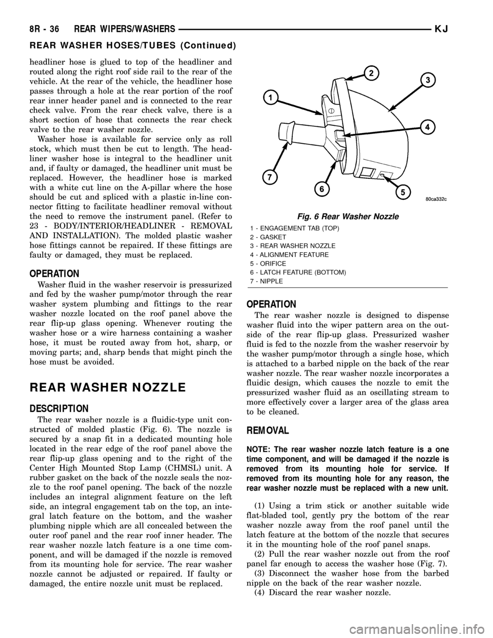
The rear washer nozzle is a fluidic-type unit con-
structed of molded plastic (Fig. 6). The nozzle is
secured by a snap fit in a dedicated mounting hole
located in the rear edge of the roof panel above the
rear flip-up glass opening and to the right of the
Center High Mounted Stop Lamp (CHMSL) unit. A
rubber gasket on the back of the nozzle seals the noz-
zle to the roof panel opening. The back of the nozzle
includes an integral alignment feature on the left
side, an integral engagement tab on the top, an inte-
gral latch feature on the bottom, and the washer
plumbing nipple which are all concealed between the
outer roof panel and the rear roof inner header. The
rear washer nozzle latch feature is a one time com-
ponent, and will be damaged if the nozzle is removed
from its mounting hole for service. The rear washer
nozzle cannot be adjusted or repaired. If faulty or
damaged, the entire nozzle unit must be replaced.
OPERATION
The rear washer nozzle is designed to dispense
washer fluid into the wiper pattern area on the out-
side of the rear flip-up glass. Pressurized washer
fluid is fed to the nozzle from the washer reservoir by
the washer pump/motor through a single hose, which
is attached to a barbed nipple on the back of the rear
washer nozzle. The rear washer nozzle incorporates a
fluidic design, which causes the nozzle to emit the
pressurized washer fluid as an oscillating stream to
more effectively cover a larger area of the glass area
to be cleaned.
REMOVAL
NOTE: The rear washer nozzle latch feature is a one
time component, and will be damaged if the nozzle is
removed from its mounting hole for service. If
removed from its mounting hole for any reason, the
rear washer nozzle must be replaced with a new unit.
(1) Using a trim stick or another suitable wide
flat-bladed tool, gently pry the bottom of the rear
washer nozzle away from the roof panel until the
latch feature at the bottom of the nozzle that secures
it in the mounting hole of the roof panel snaps.
(2) Pull the rear washer nozzle out from the roof
panel far enough to access the washer hose (Fig. 7).
(3) Disconnect the washer hose from the barbed
nipple on the back of the rear washer nozzle.
(4) Discard the rear washer nozzle.
Fig. 6 Rear Washer Nozzle
1 - ENGAGEMENT TAB (TOP)
2 - GASKET
3 - REAR WASHER NOZZLE
4 - ALIGNMENT FEATURE
5 - ORIFICE
6 - LATCH FEATURE (BOTTOM)
7 - NIPPLE
8R - 36 REAR WIPERS/WASHERSKJ
REAR WASHER HOSES/TUBES (Continued)
Page 1281 of 1803

INSPECTION
CAUTION: Oil pump pressure relief valve and
spring should not be removed from the oil pump. If
these components are disassembled and or
removed from the pump the entire oil pump assem-
bly must be replaced.
(1) Clean all parts thoroughly. Mating surface of
the oil pump housing should be smooth. If the pump
cover is scratched or grooved the oil pump assembly
should be replaced.
(2) Lay a straight edge across the pump cover sur-
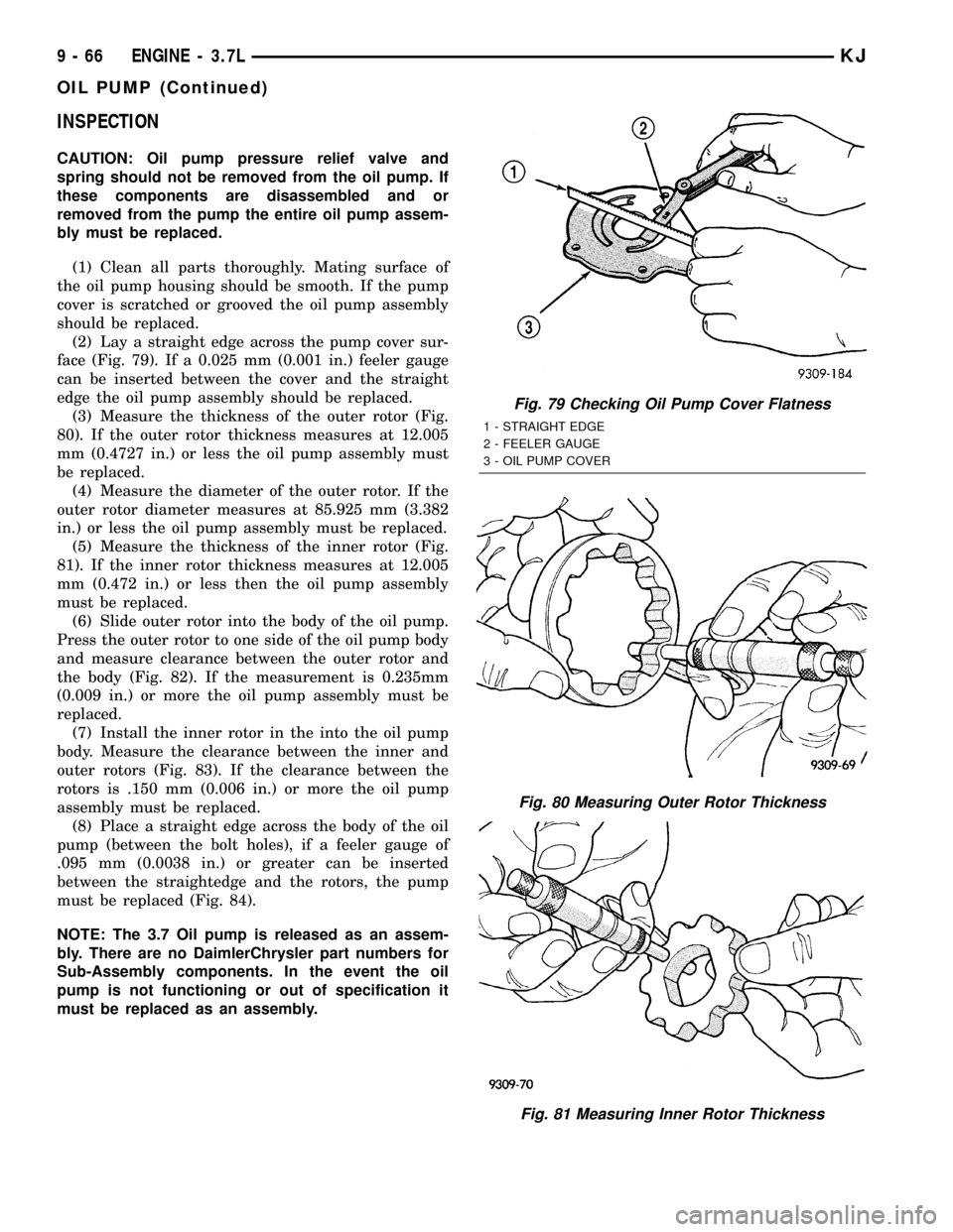
face (Fig. 79). If a 0.025 mm (0.001 in.) feeler gauge
can be inserted between the cover and the straight
edge the oil pump assembly should be replaced.
(3) Measure the thickness of the outer rotor (Fig.
80). If the outer rotor thickness measures at 12.005
mm (0.4727 in.) or less the oil pump assembly must
be replaced.
(4) Measure the diameter of the outer rotor. If the
outer rotor diameter measures at 85.925 mm (3.382
in.) or less the oil pump assembly must be replaced.
(5) Measure the thickness of the inner rotor (Fig.
81). If the inner rotor thickness measures at 12.005
mm (0.472 in.) or less then the oil pump assembly
must be replaced.
(6) Slide outer rotor into the body of the oil pump.
Press the outer rotor to one side of the oil pump body
and measure clearance between the outer rotor and
the body (Fig. 82). If the measurement is 0.235mm
(0.009 in.) or more the oil pump assembly must be
replaced.
(7) Install the inner rotor in the into the oil pump
body. Measure the clearance between the inner and
outer rotors (Fig. 83). If the clearance between the
rotors is .150 mm (0.006 in.) or more the oil pump
assembly must be replaced.
(8) Place a straight edge across the body of the oil
pump (between the bolt holes), if a feeler gauge of
.095 mm (0.0038 in.) or greater can be inserted
between the straightedge and the rotors, the pump
must be replaced (Fig. 84).
NOTE: The 3.7 Oil pump is released as an assem-
bly. There are no DaimlerChrysler part numbers for
Sub-Assembly components. In the event the oil
pump is not functioning or out of specification it
must be replaced as an assembly.
Fig. 79 Checking Oil Pump Cover Flatness
1 - STRAIGHT EDGE
2 - FEELER GAUGE
3 - OIL PUMP COVER
Fig. 80 Measuring Outer Rotor Thickness
Fig. 81 Measuring Inner Rotor Thickness
9 - 66 ENGINE - 3.7LKJ
OIL PUMP (Continued)
Page 1308 of 1803

MopartGasket Sealant in an aerosol can should be
applied using a thin, even coat sprayed completely
over both surfaces to be joined, and both sides of a
gasket. Then proceed with assembly. Material in a
can w/applicator can be brushed on evenly over the
sealing surfaces. Material in an aerosol can should be
used on engines with multi-layer steel gaskets.
STANDARD PROCEDURE - ENGINE GASKET
SURFACE PREPARATION
To ensure engine gasket sealing, proper surface
preparation must be performed, especially with the
use of aluminum engine components and multi-layer
steel cylinder head gaskets.
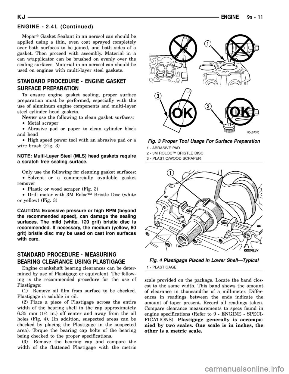
Neveruse the following to clean gasket surfaces:
²Metal scraper
²Abrasive pad or paper to clean cylinder block
and head
²High speed power tool with an abrasive pad or a
wire brush (Fig. 3)
NOTE: Multi-Layer Steel (MLS) head gaskets require
a scratch free sealing surface.
Only use the following for cleaning gasket surfaces:
²Solvent or a commercially available gasket
remover
²Plastic or wood scraper (Fig. 3)
²Drill motor with 3M RolocŸ Bristle Disc (white
or yellow) (Fig. 3)
CAUTION: Excessive pressure or high RPM (beyond
the recommended speed), can damage the sealing
surfaces. The mild (white, 120 grit) bristle disc is
recommended. If necessary, the medium (yellow, 80
grit) bristle disc may be used on cast iron surfaces
with care.
STANDARD PROCEDURE - MEASURING
BEARING CLEARANCE USING PLASTIGAGE
Engine crankshaft bearing clearances can be deter-
mined by use of Plastigage or equivalent. The follow-
ing is the recommended procedure for the use of
Plastigage:
(1) Remove oil film from surface to be checked.
Plastigage is soluble in oil.
(2) Place a piece of Plastigage across the entire
width of the bearing shell in the cap approximately
6.35 mm (1/4 in.) off center and away from the oil
holes (Fig. 4). (In addition, suspected areas can be
checked by placing the Plastigage in the suspected
area). Torque the bearing cap bolts of the bearing
being checked to the proper specifications.
(3) Remove the bearing cap and compare the
width of the flattened Plastigage with the metricscale provided on the package. Locate the band clos-
est to the same width. This band shows the amount
of clearance in thousandths of a millimeter. Differ-
ences in readings between the ends indicate the
amount of taper present. Record all readings taken.
Compare clearance measurements to specs found in
engine specifications (Refer to 9 - ENGINE - SPECI-
FICATIONS).Plastigage generally is accompa-
nied by two scales. One scale is in inches, the
other is a metric scale.
Fig. 3 Proper Tool Usage For Surface Preparation
1 - ABRASIVE PAD
2 - 3M ROLOCŸ BRISTLE DISC
3 - PLASTIC/WOOD SCRAPER
Fig. 4 Plastigage Placed in Lower ShellÐTypical
1 - PLASTIGAGE
KJENGINE9s-11
ENGINE - 2.4L (Continued)
Page 1455 of 1803

TIRES/WHEELS
TABLE OF CONTENTS
page page
TIRES/WHEELS
DIAGNOSIS AND TESTING - TIRES AND
WHEEL RUNOUT......................1
STANDARD PROCEDURE
STANDARD PROCEDURE - TIRE ROTATION . 2
STANDARD PROCEDURE - MATCH
MOUNTING...........................3
STANDARD PROCEDURE - WHEEL
BALANCING..........................4
TIRES
DESCRIPTION
DESCRIPTION - TIRES..................6
DESCRIPTION - RADIAL-PLY TIRES........6
DESCRIPTION - SPARE TIRE
&TEMPORARY........................6
DESCRIPTION - REPLACEMENT TIRES.....7
DIAGNOSIS AND TESTING
DIAGNOSIS AND TESTING - TIRE
INFLATION...........................7
DIAGNOSIS AND TESTING - TREAD WEAR
INDICATORS..........................8
DIAGNOSIS AND TESTING - TIRE WEAR
PATTERNS...........................8DIAGNOSIS AND TESTING - TIRE NOISE
OR VIBRATION........................8
STANDARD PROCEDURE - REPAIRING
LEAKS...............................8
CLEANING.............................8
SPECIFICATIONS........................8
SPARE TIRE
REMOVAL.............................8
INSTALLATION..........................9
WHEELS
DESCRIPTION..........................9
DIAGNOSIS AND TESTING - WHEELS.......10
STANDARD PROCEDURE
STANDARD PROCEDURE - WHEEL
REPLACEMENT.......................10
STANDARD PROCEDURE - WHEEL
MOUNTING..........................10
SPECIFICATIONS
SPECIFICATION......................11
STUDS
REMOVAL.............................11
INSTALLATION.........................11
TIRES/WHEELS
DIAGNOSIS AND TESTING - TIRES AND
WHEEL RUNOUT
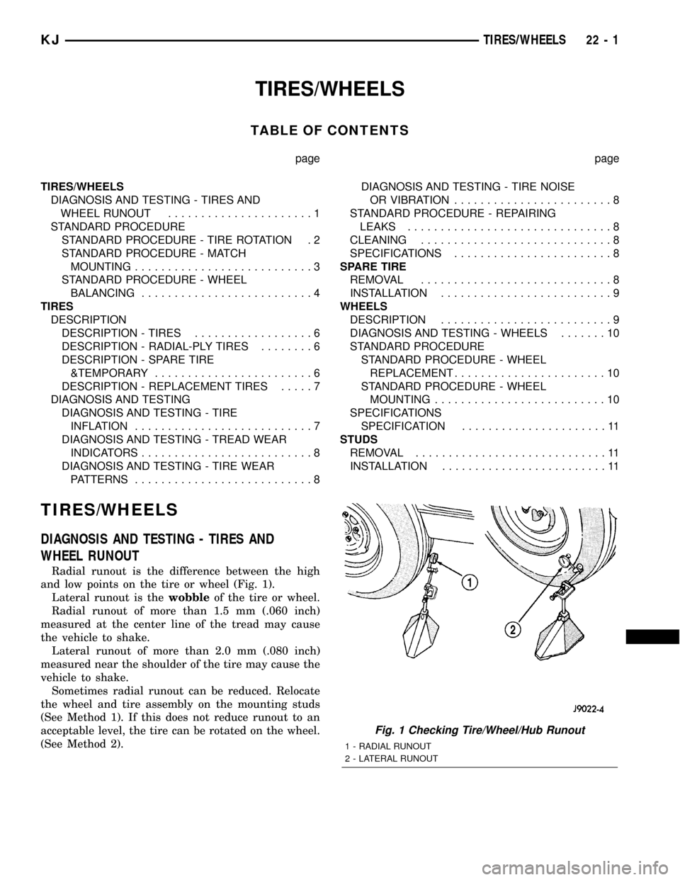
Radial runout is the difference between the high
and low points on the tire or wheel (Fig. 1).
Lateral runout is thewobbleof the tire or wheel.
Radial runout of more than 1.5 mm (.060 inch)
measured at the center line of the tread may cause
the vehicle to shake.
Lateral runout of more than 2.0 mm (.080 inch)
measured near the shoulder of the tire may cause the
vehicle to shake.
Sometimes radial runout can be reduced. Relocate
the wheel and tire assembly on the mounting studs
(See Method 1). If this does not reduce runout to an
acceptable level, the tire can be rotated on the wheel.
(See Method 2).
Fig. 1 Checking Tire/Wheel/Hub Runout
1 - RADIAL RUNOUT
2 - LATERAL RUNOUT
KJTIRES/WHEELS 22 - 1