2002 JEEP LIBERTY Gasket install
[x] Cancel search: Gasket installPage 269 of 1803

WARNING: HOT, PRESSURIZED COOLANT CAN
CAUSE INJURY BY SCALDING. COOLING SYSTEM
MUST BE PARTIALLY DRAINED BEFORE REMOV-
ING THE COOLANT TEMPERATURE SENSOR.
(1) Partially drain cooling system.
(2) Disconnect electrical connector from sensor.
(3) Remove sensor from intake manifold.
INSTALLATION
(1) Apply thread sealant to sensor threads.
(2) Install sensor to engine.
(3) Tighten sensor to 11 N´m (8 ft. lbs.) torque.
(4) Replace any lost engine coolant.
ENGINE COOLANT
THERMOSTAT
REMOVAL - 2.4L ENGINE
(1) Drain cooling system below the thermostat
level.
(2) Remove radiator upper hose from the coolant
outlet housing.
(3) Remove coolant outlet housing bolts and hous-
ing.
(4) Remove thermostat. Discard gasket and clean
both gasket sealing surfaces.
INSTALLATION - 2.4L ENGINE
(1) Place a new gasket (dipped in clean water) on
the coolant outlet connector surface. Position thermo-
stat with air bleed at the 12 o'clock position in ther-
mostat housing.
(2) Position the coolant outlet connector and gas-
ket over the thermostat, making sure thermostat is
seated in the thermostat housing.
(3) Position outlet connector to thermostat housing
and install bolts. Tighten bolts to 28 N´m (250 in.
lbs.).
(4) Install the radiator upper hose to coolant outlet
housing.
(5) Refill the cooling system.
RADIATOR
DESCRIPTION
All vehicles are equipped with a cross flow type
radiator with plastic side tanks (Fig. 4).
Plastic tanks, while stronger than brass, are sub-
ject to damage by impact, such as from tools or
wrenches. Handle radiator with care.
REMOVAL
WARNING: DO NOT REMOVE THE CYLINDER
BLOCK DRAIN PLUGS OR LOOSEN THE RADIATOR
DRAINCOCK WITH THE SYSTEM HOT AND UNDER
PRESSURE. SERIOUS BURNS FROM COOLANT
CAN OCCUR. REFER TO COOLING SYSTEM DRAIN-
ING.
Fig. 3 MAP SENSOR / ECT SENSOR - 3.7L
1 - MOUNTING SCREWS
2 - MAP SENSOR
3 - ECT SENSOR
Fig. 4 Cross Flow Radiator - Typical
1 - RADIATOR
7s - 22 ENGINEKJ
ENGINE COOLANT TEMPERATURE SENSOR (Continued)
Page 272 of 1803

RADIATOR PRESSURE CAP
DESCRIPTION
The cooling system cap is located on the coolant
pressure bottle. The cap construction includes; stain-
less steel swivel top, rubber seals and retainer, main
spring, and a spring loaded valve (Fig. 9).
OPERATION
The pressure cap allows the cooling system to oper-
ate at higher than atmospheric pressure which raises
the coolant boiling point, thus allowing increased
radiator cooling capacity. The pressure cap releases
pressure at some point within a range of 110 kPa
14 kPa (16 psi 2 psi).
A spring-loaded vent valve in the center of the cap
allows the system to pressurize and depressurize
without creating a vacuum. If the valve is stuck
open, coolant will escape to the overflow hose. There
is also a gasket in the cap to seal to the top of the
filler neck.
CAUTION: Use only the pressure cap specified for
this vehicle. Use of other pressure caps can lead to
coolant loss and overheating.
DIAGNOSIS AND TESTING - RADIATOR
PRESSURE CAP
Remove cap from radiator. Be sure that sealing
surfaces are clean. Moisten rubber gasket with water
and install the cap on pressure tester (tool 7700 or
an equivalent) (Fig. 10).Operate the tester pump and observe the gauge
pointer at its highest point. The cap release pressure
should be 124 to 145 kPa (18 to 21 psi). The cap is
satisfactory when the pressure holds steady. It is also
good if it holds pressure within the 124 to 145 kPa
(18 to 21 psi) range for 30 seconds or more. If the
pointer drops quickly, replace the cap.
CAUTION: Radiator pressure testing tools are very
sensitive to small air leaks, which will not cause
cooling system problems. A pressure cap that does
not have a history of coolant loss should not be
replaced just because it leaks slowly when tested
with this tool. Add water to tool. Turn tool upside
down and recheck pressure cap to confirm that cap
needs replacement.
CLEANING
Clean the radiator pressure cap using a mild soap
and water only.
INSPECTION
Visually inspect the pressure valve gasket on the
cap. Replace cap if the gasket is swollen, torn or
worn. Inspect the area around radiator filler neck for
white deposits that indicate a leaking cap.
Fig. 9 PRESSURE CAP
1 - MAIN SPRING
2 - GASKET RETAINER
3 - STAINLESS STEEL SWIVEL TOP
4 - RUBBER SEALS
5 - SPRING LOADED VALVE
6 - COOLANT PRESSURE BOTTLE
7 - FILLER NECK
8 - OVERFLOW NIPPLEFig. 10 Pressure Testing Radiator Pressure Cap -
Typical
1 - PRESSURE CAP
2 - TYPICAL COOLING SYSTEM PRESSURE TESTER
KJENGINE7s-25
Page 275 of 1803

(9) Remove the accessory drive bracket.
(10) Remove the timing belt (Refer to 9 - ENGINE/
VALVE TIMING/TIMING BELT AND SPROCKET(S)
- REMOVAL).
(11) Remove timing belt idler pulley.
(12) Hold camshaft sprocket with Special tool
C-4687 and adaptor C-4687-1 while removing bolt.
Remove both cam sprockets.
(13) Remove the timing belt rear cover (Refer to 9
- ENGINE/VALVE TIMING/TIMING BELT COV-
ER(S) - REMOVAL).
(14) Remove water pump to engine attaching
screws (Fig. 15).
INSPECTION
Replace water pump body assembly if it has any of
these defects:
(1) Cracks or damage on the body.
(2) Coolant leaks from the shaft seal, evident by
wet coolant traces on the pump body.
(3) Loose or rough turning bearing.
(4) Impeller rubs either the pump body or the
engine block.
(5) Impeller loose or damaged.
(6) Sprocket or sprocket flange loose or damaged.
INSTALLATION - 2.4L ENGINE
(1) Install new O-ring gasket in water pump body
O-ring locating groove (Fig. 16).
CAUTION: Make sure O-ring is properly seated in
water pump groove before tightening screws. An
improperly located O-ring may be damaged and
cause a coolant leak.
(2) Assemble pump body to block and tighten
screws to 12 N´m (105 in. lbs.). Pressurize cooling
system to 103.4 Kpa (15 psi) with pressure tester and
check water pump shaft seal and O-ring for leaks.
(3) Rotate pump by hand to check for freedom of
movement.
(4) Install the timing belt rear cover (Refer to 9 -
ENGINE/VALVE TIMING/TIMING BELT COVER(S)
- INSTALLATION).
(5) Install camshaft sprockets and target ring.
Torque bolts to 101 N´m (75 ft. lbs.) while holding
camshaft sprocket with Special tool C-4687 and
adaptor C-4687-1.
(6) Install timing belt idler pulley and torque
mounting bolt to 61 N´m (45 ft. lbs.).
(7) Install the timing belt (Refer to 9 - ENGINE/
VALVE TIMING/TIMING BELT AND SPROCKET(S)
- INSTALLATION).
Fig. 15 Water Pump - 2.4L
1 - CYLINDER BLOCK
2 - WATER PUMP
Fig. 16 Water Pump Body
1 - IMPELLER
2 - WATER PUMP BODY
3 - O-RING LOCATING GROOVE
7s - 28 ENGINEKJ
WATER PUMP - 2.4L (Continued)
Page 737 of 1803
headliner hose is glued to top of the headliner and
routed along the right roof side rail to the rear of the
vehicle. At the rear of the vehicle, the headliner hose
passes through a hole at the rear portion of the roof
rear inner header panel and is connected to the rear
check valve. From the rear check valve, there is a
short section of hose that connects the rear check
valve to the rear washer nozzle.
Washer hose is available for service only as roll
stock, which must then be cut to length. The head-
liner washer hose is integral to the headliner unit
and, if faulty or damaged, the headliner unit must be
replaced. However, the headliner hose is marked
with a white cut line on the A-pillar where the hose
should be cut and spliced with a plastic in-line con-
nector fitting to facilitate headliner removal without
the need to remove the instrument panel. (Refer to
23 - BODY/INTERIOR/HEADLINER - REMOVAL
AND INSTALLATION). The molded plastic washer
hose fittings cannot be repaired. If these fittings are
faulty or damaged, they must be replaced.
OPERATION
Washer fluid in the washer reservoir is pressurized
and fed by the washer pump/motor through the rear
washer system plumbing and fittings to the rear
washer nozzle located on the roof panel above the
rear flip-up glass opening. Whenever routing the
washer hose or a wire harness containing a washer
hose, it must be routed away from hot, sharp, or
moving parts; and, sharp bends that might pinch the
hose must be avoided.
REAR WASHER NOZZLE
DESCRIPTION
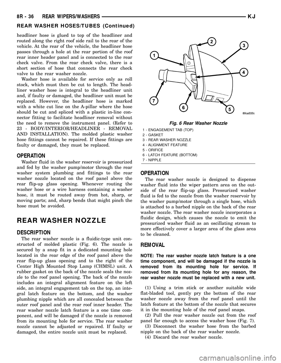
The rear washer nozzle is a fluidic-type unit con-
structed of molded plastic (Fig. 6). The nozzle is
secured by a snap fit in a dedicated mounting hole
located in the rear edge of the roof panel above the
rear flip-up glass opening and to the right of the
Center High Mounted Stop Lamp (CHMSL) unit. A
rubber gasket on the back of the nozzle seals the noz-
zle to the roof panel opening. The back of the nozzle
includes an integral alignment feature on the left
side, an integral engagement tab on the top, an inte-
gral latch feature on the bottom, and the washer
plumbing nipple which are all concealed between the
outer roof panel and the rear roof inner header. The
rear washer nozzle latch feature is a one time com-
ponent, and will be damaged if the nozzle is removed
from its mounting hole for service. The rear washer
nozzle cannot be adjusted or repaired. If faulty or
damaged, the entire nozzle unit must be replaced.
OPERATION
The rear washer nozzle is designed to dispense
washer fluid into the wiper pattern area on the out-
side of the rear flip-up glass. Pressurized washer
fluid is fed to the nozzle from the washer reservoir by
the washer pump/motor through a single hose, which
is attached to a barbed nipple on the back of the rear
washer nozzle. The rear washer nozzle incorporates a
fluidic design, which causes the nozzle to emit the
pressurized washer fluid as an oscillating stream to
more effectively cover a larger area of the glass area
to be cleaned.
REMOVAL
NOTE: The rear washer nozzle latch feature is a one
time component, and will be damaged if the nozzle is
removed from its mounting hole for service. If
removed from its mounting hole for any reason, the
rear washer nozzle must be replaced with a new unit.
(1) Using a trim stick or another suitable wide
flat-bladed tool, gently pry the bottom of the rear
washer nozzle away from the roof panel until the
latch feature at the bottom of the nozzle that secures
it in the mounting hole of the roof panel snaps.
(2) Pull the rear washer nozzle out from the roof
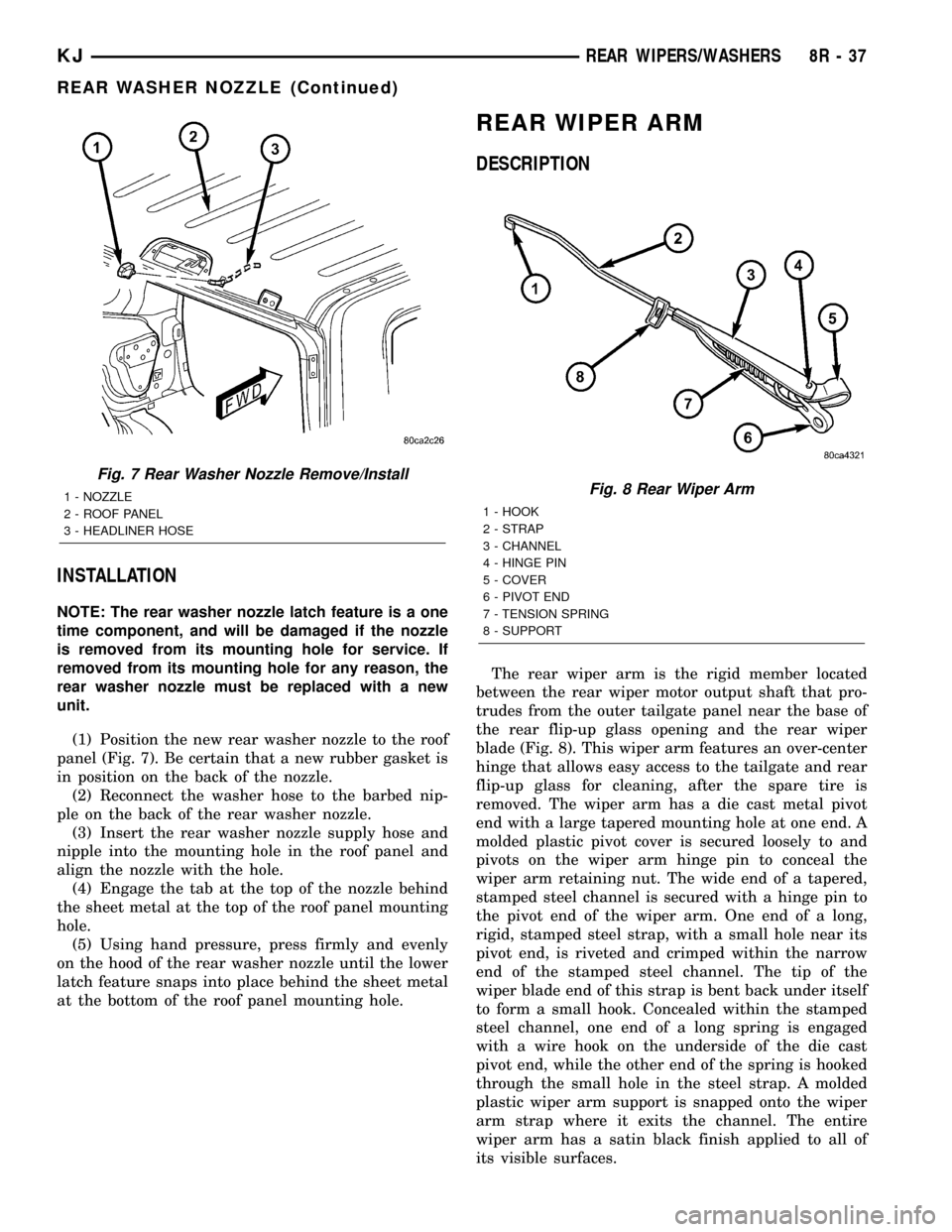
panel far enough to access the washer hose (Fig. 7).
(3) Disconnect the washer hose from the barbed
nipple on the back of the rear washer nozzle.
(4) Discard the rear washer nozzle.
Fig. 6 Rear Washer Nozzle
1 - ENGAGEMENT TAB (TOP)
2 - GASKET
3 - REAR WASHER NOZZLE
4 - ALIGNMENT FEATURE
5 - ORIFICE
6 - LATCH FEATURE (BOTTOM)
7 - NIPPLE
8R - 36 REAR WIPERS/WASHERSKJ
REAR WASHER HOSES/TUBES (Continued)
Page 738 of 1803
INSTALLATION
NOTE: The rear washer nozzle latch feature is a one
time component, and will be damaged if the nozzle
is removed from its mounting hole for service. If
removed from its mounting hole for any reason, the
rear washer nozzle must be replaced with a new
unit.
(1) Position the new rear washer nozzle to the roof
panel (Fig. 7). Be certain that a new rubber gasket is
in position on the back of the nozzle.
(2) Reconnect the washer hose to the barbed nip-
ple on the back of the rear washer nozzle.
(3) Insert the rear washer nozzle supply hose and
nipple into the mounting hole in the roof panel and
align the nozzle with the hole.
(4) Engage the tab at the top of the nozzle behind
the sheet metal at the top of the roof panel mounting
hole.
(5) Using hand pressure, press firmly and evenly
on the hood of the rear washer nozzle until the lower
latch feature snaps into place behind the sheet metal
at the bottom of the roof panel mounting hole.
REAR WIPER ARM
DESCRIPTION
The rear wiper arm is the rigid member located
between the rear wiper motor output shaft that pro-
trudes from the outer tailgate panel near the base of
the rear flip-up glass opening and the rear wiper
blade (Fig. 8). This wiper arm features an over-center
hinge that allows easy access to the tailgate and rear
flip-up glass for cleaning, after the spare tire is
removed. The wiper arm has a die cast metal pivot
end with a large tapered mounting hole at one end. A
molded plastic pivot cover is secured loosely to and
pivots on the wiper arm hinge pin to conceal the
wiper arm retaining nut. The wide end of a tapered,
stamped steel channel is secured with a hinge pin to
the pivot end of the wiper arm. One end of a long,
rigid, stamped steel strap, with a small hole near its
pivot end, is riveted and crimped within the narrow
end of the stamped steel channel. The tip of the
wiper blade end of this strap is bent back under itself
to form a small hook. Concealed within the stamped
steel channel, one end of a long spring is engaged
with a wire hook on the underside of the die cast
pivot end, while the other end of the spring is hooked
through the small hole in the steel strap. A molded
plastic wiper arm support is snapped onto the wiper
arm strap where it exits the channel. The entire
wiper arm has a satin black finish applied to all of
its visible surfaces.
Fig. 7 Rear Washer Nozzle Remove/Install
1 - NOZZLE
2 - ROOF PANEL
3 - HEADLINER HOSEFig. 8 Rear Wiper Arm
1 - HOOK
2 - STRAP
3 - CHANNEL
4 - HINGE PIN
5 - COVER
6 - PIVOT END
7 - TENSION SPRING
8 - SUPPORT
KJREAR WIPERS/WASHERS 8R - 37
REAR WASHER NOZZLE (Continued)
Page 743 of 1803
REMOVAL
(1) Disconnect and isolate the battery negative
cable.
(2) Remove the rear wiper arm from the rear
wiper motor output shaft. (Refer to 8 - ELECTRI-
CAL/REAR WIPERS/WASHERS/REAR WIPER ARM
- REMOVAL).
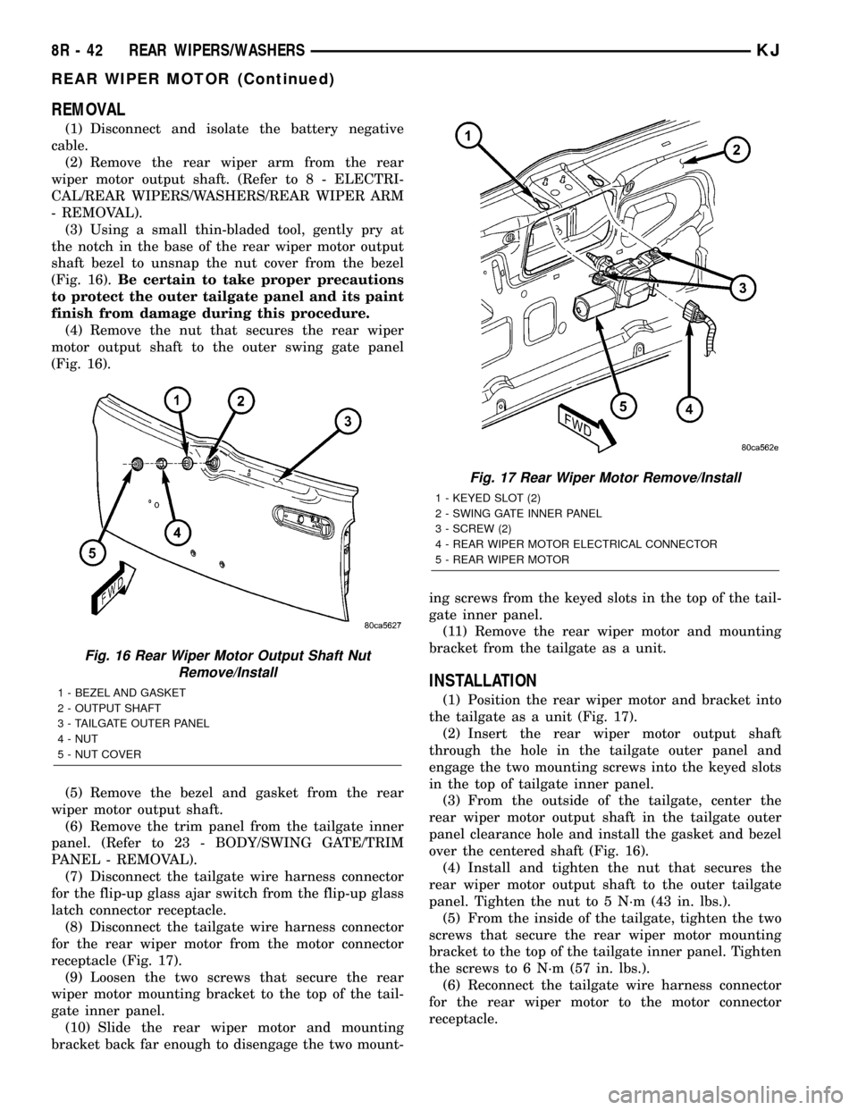
(3) Using a small thin-bladed tool, gently pry at
the notch in the base of the rear wiper motor output
shaft bezel to unsnap the nut cover from the bezel
(Fig. 16).Be certain to take proper precautions
to protect the outer tailgate panel and its paint
finish from damage during this procedure.
(4) Remove the nut that secures the rear wiper
motor output shaft to the outer swing gate panel
(Fig. 16).
(5) Remove the bezel and gasket from the rear
wiper motor output shaft.
(6) Remove the trim panel from the tailgate inner
panel. (Refer to 23 - BODY/SWING GATE/TRIM
PANEL - REMOVAL).
(7) Disconnect the tailgate wire harness connector
for the flip-up glass ajar switch from the flip-up glass
latch connector receptacle.
(8) Disconnect the tailgate wire harness connector
for the rear wiper motor from the motor connector
receptacle (Fig. 17).
(9) Loosen the two screws that secure the rear
wiper motor mounting bracket to the top of the tail-
gate inner panel.
(10) Slide the rear wiper motor and mounting
bracket back far enough to disengage the two mount-ing screws from the keyed slots in the top of the tail-
gate inner panel.
(11) Remove the rear wiper motor and mounting
bracket from the tailgate as a unit.
INSTALLATION
(1) Position the rear wiper motor and bracket into
the tailgate as a unit (Fig. 17).
(2) Insert the rear wiper motor output shaft
through the hole in the tailgate outer panel and
engage the two mounting screws into the keyed slots
in the top of tailgate inner panel.
(3) From the outside of the tailgate, center the
rear wiper motor output shaft in the tailgate outer
panel clearance hole and install the gasket and bezel
over the centered shaft (Fig. 16).
(4) Install and tighten the nut that secures the
rear wiper motor output shaft to the outer tailgate
panel. Tighten the nut to 5 N´m (43 in. lbs.).
(5) From the inside of the tailgate, tighten the two
screws that secure the rear wiper motor mounting
bracket to the top of the tailgate inner panel. Tighten
the screws to 6 N´m (57 in. lbs.).
(6) Reconnect the tailgate wire harness connector
for the rear wiper motor to the motor connector
receptacle.
Fig. 16 Rear Wiper Motor Output Shaft Nut
Remove/Install
1 - BEZEL AND GASKET
2 - OUTPUT SHAFT
3 - TAILGATE OUTER PANEL
4 - NUT
5 - NUT COVER
Fig. 17 Rear Wiper Motor Remove/Install
1 - KEYED SLOT (2)
2 - SWING GATE INNER PANEL
3 - SCREW (2)
4 - REAR WIPER MOTOR ELECTRICAL CONNECTOR
5 - REAR WIPER MOTOR
8R - 42 REAR WIPERS/WASHERSKJ
REAR WIPER MOTOR (Continued)
Page 1216 of 1803
ENGINE - 3.7L
TABLE OF CONTENTS
page page
ENGINE - 3.7L
DESCRIPTION..........................3
DIAGNOSIS AND TESTING
DIAGNOSIS AND TESTING - ENGINE
DIAGNOSIS - INTRODUCTION............4
DIAGNOSIS AND TESTING - ENGINE
DIAGNOSIS - PERFORMANCE............4
DIAGNOSIS AND TESTING - ENGINE
DIAGNOSIS - MECHANICAL..............6
DIAGNOSIS AND TESTING - ENGINE
DIAGNOSIS - LUBRICATION..............7
DIAGNOSIS AND TESTING - CYLINDER
COMPRESSION PRESSURE..............8
DIAGNOSIS AND TESTING - CYLINDER
COMBUSTION PRESSURE LEAKAGE.......8
STANDARD PROCEDURE
STANDARD PROCEDURE - ENGINE
GASKET SURFACE PREPARATION.........9
STANDARD PROCEDURE - REPAIR
DAMAGED OR WORN THREADS..........9
STANDARD PROCEDURE - ENGINE CORE
AND OIL GALLERY PLUGS..............10
REMOVAL.............................10
INSTALLATION.........................11
SPECIFICATIONS
TORQUE............................12
3.7L ENGINE.........................12
SPECIAL TOOLS
3.7L ENGINE.........................15
AIR CLEANER ELEMENT
REMOVAL - 3.7L........................19
INSTALLATION - 3.7L....................19
CYLINDER HEAD - LEFT
DESCRIPTION - VALVE GUIDES...........19
DIAGNOSIS AND TESTING
DIAGNOSIS AND TESTING - HYDRAULIC
LASH ADJUSTER.....................19
DIAGNOSIS AND TESTING - CYLINDER
HEAD GASKET.......................19
REMOVAL.............................20
CLEANING............................22
INSTALLATION.........................22
CAMSHAFT(S)
DESCRIPTION.........................23
REMOVAL.............................24
INSTALLATION.........................25
CYLINDER HEAD COVER(S)
DESCRIPTION.........................25
REMOVAL.............................25INSTALLATION.........................26
INTAKE/EXHAUST VALVES & SEATS
DESCRIPTION.........................26
STANDARD PROCEDURE - REFACING......26
REMOVAL.............................27
INSTALLATION.........................28
ROCKER ARM
DESCRIPTION.........................29
VALVE GUIDE SEALS
DESCRIPTION.........................29
VALVE SPRINGS
DESCRIPTION.........................29
REMOVAL.............................29
INSTALLATION.........................29
CYLINDER HEAD - RIGHT
DESCRIPTION
DESCRIPTION - CYLINDER HEAD........30
DESCRIPTION - VALVE GUIDES..........30
DESCRIPTION........................30
DIAGNOSIS AND TESTING
DIAGNOSIS AND TESTING - HYDRAULIC
LASH ADJUSTER.....................30
DIAGNOSIS AND TESTING - CYLINDER
HEAD GASKET.......................30
REMOVAL.............................31
CLEANING............................31
INSPECTION..........................32
INSTALLATION.........................32
CAMSHAFT(S)
DESCRIPTION.........................33
REMOVAL.............................33
INSTALLATION.........................33
CYLINDER HEAD COVER(S)
REMOVAL.............................34
INSTALLATION.........................34
INTAKE/EXHAUST VALVES & SEATS
STANDARD PROCEDURE - REFACING......34
REMOVAL.............................35
INSTALLATION.........................36
ROCKER ARM
DESCRIPTION.........................37
REMOVAL.............................37
INSTALLATION.........................37
VALVE GUIDE SEALS
DESCRIPTION.........................38
VALVE SPRINGS
DESCRIPTION.........................38
REMOVAL.............................38
INSTALLATION.........................38
KJENGINE - 3.7L 9 - 1
Page 1229 of 1803
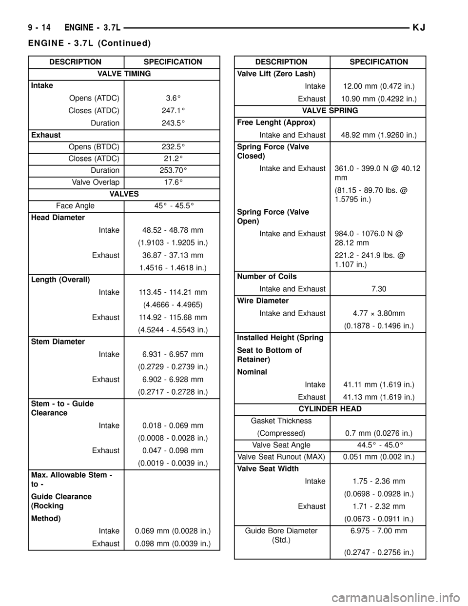
DESCRIPTION SPECIFICATION
VALVE TIMING
Intake
Opens (ATDC) 3.6É
Closes (ATDC) 247.1É
Duration 243.5É
Exhaust
Opens (BTDC) 232.5É
Closes (ATDC) 21.2É
Duration 253.70É
Valve Overlap 17.6É
VA LV E S
Face Angle 45É - 45.5É
Head Diameter
Intake 48.52 - 48.78 mm
(1.9103 - 1.9205 in.)
Exhaust 36.87 - 37.13 mm
1.4516 - 1.4618 in.)
Length (Overall)
Intake 113.45 - 114.21 mm
(4.4666 - 4.4965)
Exhaust 114.92 - 115.68 mm
(4.5244 - 4.5543 in.)
Stem Diameter
Intake 6.931 - 6.957 mm
(0.2729 - 0.2739 in.)
Exhaust 6.902 - 6.928 mm
(0.2717 - 0.2728 in.)
Stem - to - Guide
Clearance
Intake 0.018 - 0.069 mm
(0.0008 - 0.0028 in.)
Exhaust 0.047 - 0.098 mm
(0.0019 - 0.0039 in.)
Max. Allowable Stem -
to -
Guide Clearance
(Rocking
Method)
Intake 0.069 mm (0.0028 in.)
Exhaust 0.098 mm (0.0039 in.)DESCRIPTION SPECIFICATION
Valve Lift (Zero Lash)
Intake 12.00 mm (0.472 in.)
Exhaust 10.90 mm (0.4292 in.)
VALVE SPRING
Free Lenght (Approx)
Intake and Exhaust 48.92 mm (1.9260 in.)
Spring Force (Valve
Closed)
Intake and Exhaust 361.0 - 399.0 N @ 40.12
mm
(81.15 - 89.70 lbs. @
1.5795 in.)
Spring Force (Valve
Open)
Intake and Exhaust 984.0 - 1076.0 N @
28.12 mm
221.2 - 241.9 lbs. @
1.107 in.)
Number of Coils
Intake and Exhaust 7.30
Wire Diameter
Intake and Exhaust 4.77 ý 3.80mm
(0.1878 - 0.1496 in.)
Installed Height (Spring
Seat to Bottom of
Retainer)
Nominal
Intake 41.11 mm (1.619 in.)
Exhaust 41.13 mm (1.619 in.)
CYLINDER HEAD
Gasket Thickness
(Compressed) 0.7 mm (0.0276 in.)
Valve Seat Angle 44.5É - 45.0É
Valve Seat Runout (MAX) 0.051 mm (0.002 in.)
Valve Seat Width
Intake 1.75 - 2.36 mm
(0.0698 - 0.0928 in.)
Exhaust 1.71 - 2.32 mm
(0.0673 - 0.0911 in.)
Guide Bore Diameter
(Std.)6.975 - 7.00 mm
(0.2747 - 0.2756 in.)
9 - 14 ENGINE - 3.7LKJ
ENGINE - 3.7L (Continued)