2002 JEEP LIBERTY Cylinder head repair
[x] Cancel search: Cylinder head repairPage 392 of 1803

(4) Connect the ohmmeter between terminals 87
and 30. The ohmmeter should not show continuity at
this time.
(5) Connect one end of a jumper wire (16 gauge or
smaller) to relay terminal 85. Connect the other end
of the jumper wire to the ground side of a 12 volt
power source.
(6) Connect one end of another jumper wire (16
gauge or smaller) to the power side of the 12 volt
power source.Do not attach the other end of the
jumper wire to the relay at this time.
WARNING: DO NOT ALLOW OHMMETER TO CON-
TACT TERMINALS 85 OR 86 DURING THIS TEST.
DAMAGE TO OHMMETER MAY RESULT.
(7) Attach the other end of the jumper wire to
relay terminal 86. This activates the relay. The ohm-
meter should now show continuity between relay ter-
minals 87 and 30. The ohmmeter should not show
continuity between relay terminals 87A and 30.
(8) Disconnect jumper wires.
(9) Replace the relay if it did not pass the continu-
ity and resistance tests. If the relay passed the tests,
it operates properly. Check the remainder of the ASD
and fuel pump relay circuits. Refer to 8, Wiring Dia-
grams.
REMOVAL
The ASD relay is located in the Power Distribution
Center (PDC) (Fig. 4). Refer to label on PDC cover
for relay location.(1) Remove PDC cover.
(2) Remove relay from PDC.
(3) Check condition of relay terminals and PDC
connector terminals for damage or corrosion. Repair
if necessary before installing relay.
(4) Check for pin height (pin height should be the
same for all terminals within the PDC connector).
Repair if necessary before installing relay.
INSTALLATION
The ASD relay is located in the Power Distribution
Center (PDC). Refer to label on PDC cover for relay
location.
(1) Install relay to PDC.
(2) Install cover to PDC.
CAMSHAFT POSITION
SENSOR
DESCRIPTION
DESCRIPTION - 2.4L
The Camshaft Position Sensor (CMP) on the 2.4L
4±cylinder engine is bolted to the right-front side of
the cylinder head (Fig. 5).
Fig. 4 POWER DISTRIBUTION CENTER (PDC)
1 - BATTERY
2 - PDC
3 - PDC COVER
Fig. 5 CMP LOCATION - 2.4L
1 - CMP SENSOR
2 - ELECTRICAL CONNECTOR
3-
4 - SLOTTED HOLES
5 - MOUNTING BOLTS (2)
KJIGNITION CONTROL 8I - 5
AUTO SHUT DOWN RELAY (Continued)
Page 692 of 1803

(2) Position the lock lever onto the pin on the back
of the door lock cylinder with the lever oriented
toward the rear.
(3) Install the retainer clip onto the pin on the
back of the door lock cylinder. Be certain that the
center tab of the retainer is engaged in the retention
hole on the lock lever.
(4) Reinstall the outside door handle unit onto the
outer door panel. (Refer to 23 - BODY/DOOR -
FRONT/EXTERIOR HANDLE - INSTALLATION).
(5) Reconnect the battery negative cable.
HOOD AJAR SWITCH
DESCRIPTION
The hood ajar switch is a normally closed, single
pole momentary switch that is used only on vehicles
equipped with the Vehicle Theft Security System
(VTSS) for sale in certain markets where it is
required equipment (Fig. 4). This switch consists of a
molded plastic body with a molded plastic mounting
bezel. The switch body has an integral molded con-nector receptacle on the lower end, while the spring-
loaded switch plunger extends from the upper end.
Two external latches integral to the mounting bezel
lock the switch into a keyed mounting hole in the
stamped steel switch mounting bracket. The mount-
ing bracket is fastened with two screws to the right
inner fender shield near the fender ledge in the
engine compartment. A molded plastic striker with
an integral retainer and mounting tab is secured to
the underside of the hood panel inner reinforcement
to actuate the switch plunger as the hood panel is
closed (Fig. 5). A single take out of the headlamp and
dash wire harness connects the switch to the vehicle
electrical system. The switch receives a path to
ground at all times through another take out of the
headlamp and dash wire harness with an eyelet ter-
minal connector that is secured by a ground screw to
the left inner fender shield in the engine compart-
ment.
The hood ajar switch cannot be adjusted or
repaired and, if faulty or damaged, it must be
replaced. The hood ajar switch striker is not intended
for reuse. If the striker is removed from the hood
inner reinforcement for any reason, it must be
replaced with a new unit.
Fig. 4 Hood Ajar Switch
1 - INNER FENDER
2 - SCREW (2)
3 - BRACKET
4 - HOOD AJAR SWITCH
5 - WIRE HARNESS CONNECTOR
Fig. 5 Hood Ajar Switch Striker
1 - STRIKER
2-TAB
3 - INNER HOOD REINFORCEMENT
4 - RETAINER
KJVEHICLE THEFT SECURITY 8Q - 11
DOOR CYLINDER LOCK SWITCH (Continued)
Page 699 of 1803

(2) Install and tighten the two screws that secure
the alarm siren module to the front extension of the
right front wheel house panel. Tighten the screws to
6 N´m (50 in. lbs.).
(3) Reconnect the headlamp and dash wire harness
connector for the alarm siren module to the module
connector receptacle.
(4) Reconnect the battery negative cable.
NOTE: If the alarm siren module has been replaced
with a new unit, the new unit MUST be configured
in the Intrusion Transceiver Module (ITM) before the
Vehicle Theft Security System can operate as
designed. The use of a DRBIIITscan tool is required
to configure the alarm siren module settings in the
ITM. Refer to the appropriate diagnostic informa-
tion.
TRANSPONDER KEY
DESCRIPTION
Each ignition key used in the Sentry Key Immobi-
lizer System (SKIS) has an integral transponder chip
(Fig. 15). Ignition keys with this feature can be
readily identified by a gray rubber cap molded onto
the head of the key, while conventional ignition keys
have a black molded rubber cap. The transponderchip is concealed beneath the molded rubber cap,
where it is molded within a plastic mount into the
head of the metal key. In addition to being cut to
match the mechanical coding of the ignition lock cyl-
inder, each new Sentry Key has a unique transpon-
der identification code permanently programmed into
it by the manufacturer. The Sentry Key transponder
cannot be adjusted or repaired. If faulty or damaged,
the entire key must be replaced.
OPERATION
When the ignition switch is turned to the On posi-
tion, the Sentry Key Immobilizer Module (SKIM)
communicates through its antenna with the Sentry
Key transponder using a Radio Frequency (RF) sig-
nal. The SKIM then listens for a RF response from
the transponder through the same antenna. The Sen-
try Key transponder chip is within the range of the
SKIM transceiver antenna ring when it is inserted
into the ignition lock cylinder. The SKIM determines
whether a valid key is present in the ignition lock
cylinder based upon the response from the transpon-
der. If a valid key is detected, that fact is communi-
cated by the SKIM to the Powertrain Control Module
(PCM) over the Programmable Communications
Interface (PCI) data bus, and the PCM allows the
engine to continue running. If the PCM receives an
invalid key message, or receives no message from the
SKIM over the PCI data bus, the engine will be dis-
abled after about two seconds of operation. The Elec-
troMechanical Instrument Cluster (EMIC) will also
respond to the invalid key message on the PCI data
bus by flashing the SKIS indicator on and off.
Fig. 14 Siren Remove/Install
1 - SCREW (2)
2 - WIRE HARNESS CONNECTOR
3 - SIREN
Fig. 15 Sentry Key Immobilizer Transponder
1 - MOLDED CAP
2 - TRANSPONDER CHIP
3 - MOLDED CAP REMOVED
4 - TRANSPONDER KEY
8Q - 18 VEHICLE THEFT SECURITYKJ
SIREN (Continued)
Page 1216 of 1803

ENGINE - 3.7L
TABLE OF CONTENTS
page page
ENGINE - 3.7L
DESCRIPTION..........................3
DIAGNOSIS AND TESTING
DIAGNOSIS AND TESTING - ENGINE
DIAGNOSIS - INTRODUCTION............4
DIAGNOSIS AND TESTING - ENGINE
DIAGNOSIS - PERFORMANCE............4
DIAGNOSIS AND TESTING - ENGINE
DIAGNOSIS - MECHANICAL..............6
DIAGNOSIS AND TESTING - ENGINE
DIAGNOSIS - LUBRICATION..............7
DIAGNOSIS AND TESTING - CYLINDER
COMPRESSION PRESSURE..............8
DIAGNOSIS AND TESTING - CYLINDER
COMBUSTION PRESSURE LEAKAGE.......8
STANDARD PROCEDURE
STANDARD PROCEDURE - ENGINE
GASKET SURFACE PREPARATION.........9
STANDARD PROCEDURE - REPAIR
DAMAGED OR WORN THREADS..........9
STANDARD PROCEDURE - ENGINE CORE
AND OIL GALLERY PLUGS..............10
REMOVAL.............................10
INSTALLATION.........................11
SPECIFICATIONS
TORQUE............................12
3.7L ENGINE.........................12
SPECIAL TOOLS
3.7L ENGINE.........................15
AIR CLEANER ELEMENT
REMOVAL - 3.7L........................19
INSTALLATION - 3.7L....................19
CYLINDER HEAD - LEFT
DESCRIPTION - VALVE GUIDES...........19
DIAGNOSIS AND TESTING
DIAGNOSIS AND TESTING - HYDRAULIC
LASH ADJUSTER.....................19
DIAGNOSIS AND TESTING - CYLINDER
HEAD GASKET.......................19
REMOVAL.............................20
CLEANING............................22
INSTALLATION.........................22
CAMSHAFT(S)
DESCRIPTION.........................23
REMOVAL.............................24
INSTALLATION.........................25
CYLINDER HEAD COVER(S)
DESCRIPTION.........................25
REMOVAL.............................25INSTALLATION.........................26
INTAKE/EXHAUST VALVES & SEATS
DESCRIPTION.........................26
STANDARD PROCEDURE - REFACING......26
REMOVAL.............................27
INSTALLATION.........................28
ROCKER ARM
DESCRIPTION.........................29
VALVE GUIDE SEALS
DESCRIPTION.........................29
VALVE SPRINGS
DESCRIPTION.........................29
REMOVAL.............................29
INSTALLATION.........................29
CYLINDER HEAD - RIGHT
DESCRIPTION
DESCRIPTION - CYLINDER HEAD........30
DESCRIPTION - VALVE GUIDES..........30
DESCRIPTION........................30
DIAGNOSIS AND TESTING
DIAGNOSIS AND TESTING - HYDRAULIC
LASH ADJUSTER.....................30
DIAGNOSIS AND TESTING - CYLINDER
HEAD GASKET.......................30
REMOVAL.............................31
CLEANING............................31
INSPECTION..........................32
INSTALLATION.........................32
CAMSHAFT(S)
DESCRIPTION.........................33
REMOVAL.............................33
INSTALLATION.........................33
CYLINDER HEAD COVER(S)
REMOVAL.............................34
INSTALLATION.........................34
INTAKE/EXHAUST VALVES & SEATS
STANDARD PROCEDURE - REFACING......34
REMOVAL.............................35
INSTALLATION.........................36
ROCKER ARM
DESCRIPTION.........................37
REMOVAL.............................37
INSTALLATION.........................37
VALVE GUIDE SEALS
DESCRIPTION.........................38
VALVE SPRINGS
DESCRIPTION.........................38
REMOVAL.............................38
INSTALLATION.........................38
KJENGINE - 3.7L 9 - 1
Page 1219 of 1803

DIAGNOSIS AND TESTING
DIAGNOSIS AND TESTING - ENGINE
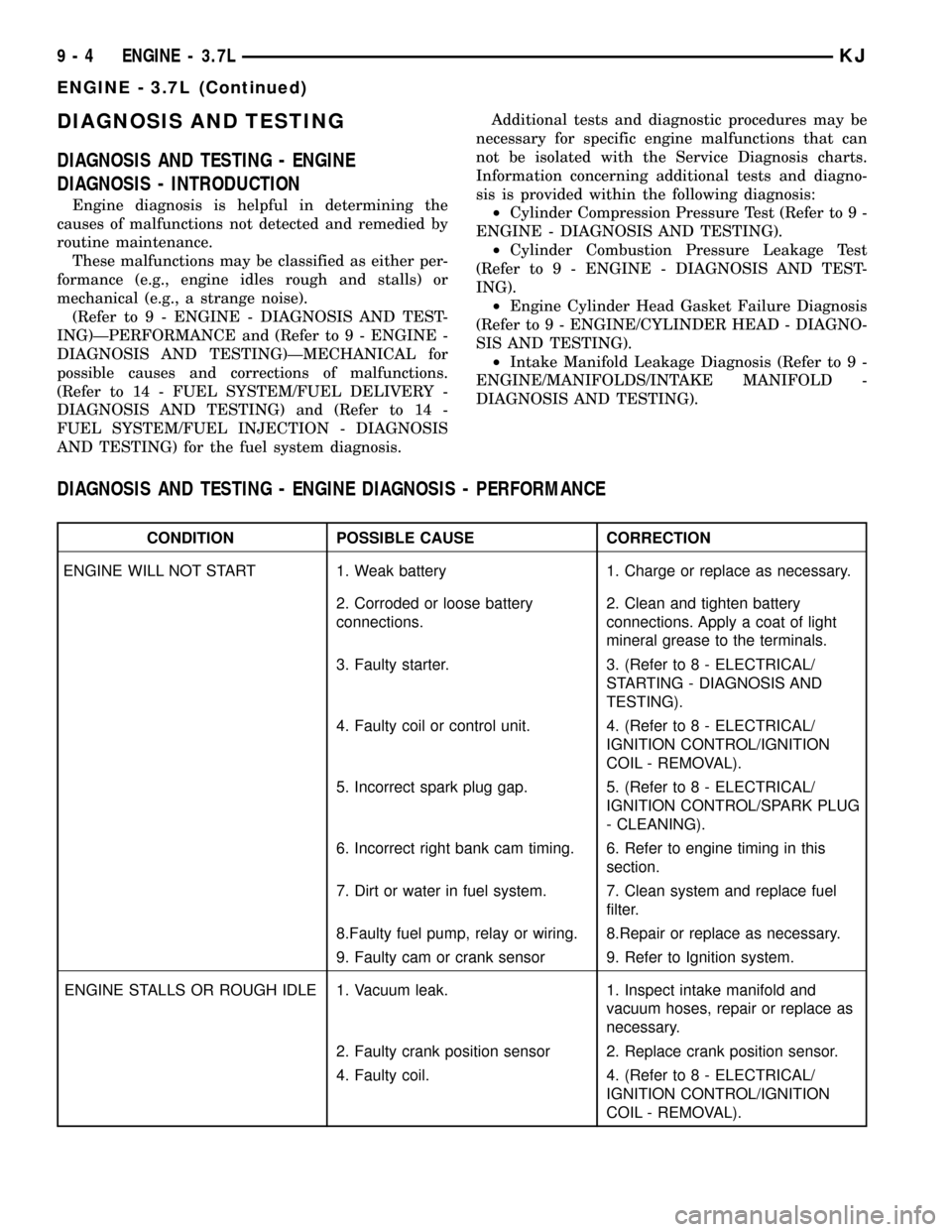
DIAGNOSIS - INTRODUCTION
Engine diagnosis is helpful in determining the
causes of malfunctions not detected and remedied by
routine maintenance.
These malfunctions may be classified as either per-
formance (e.g., engine idles rough and stalls) or
mechanical (e.g., a strange noise).
(Refer to 9 - ENGINE - DIAGNOSIS AND TEST-
ING)ÐPERFORMANCE and (Refer to 9 - ENGINE -
DIAGNOSIS AND TESTING)ÐMECHANICAL for
possible causes and corrections of malfunctions.
(Refer to 14 - FUEL SYSTEM/FUEL DELIVERY -
DIAGNOSIS AND TESTING) and (Refer to 14 -
FUEL SYSTEM/FUEL INJECTION - DIAGNOSIS
AND TESTING) for the fuel system diagnosis.Additional tests and diagnostic procedures may be
necessary for specific engine malfunctions that can
not be isolated with the Service Diagnosis charts.
Information concerning additional tests and diagno-
sis is provided within the following diagnosis:
²Cylinder Compression Pressure Test (Refer to 9 -
ENGINE - DIAGNOSIS AND TESTING).
²Cylinder Combustion Pressure Leakage Test
(Refer to 9 - ENGINE - DIAGNOSIS AND TEST-
ING).
²Engine Cylinder Head Gasket Failure Diagnosis
(Refer to 9 - ENGINE/CYLINDER HEAD - DIAGNO-
SIS AND TESTING).
²Intake Manifold Leakage Diagnosis (Refer to 9 -
ENGINE/MANIFOLDS/INTAKE MANIFOLD -
DIAGNOSIS AND TESTING).
DIAGNOSIS AND TESTING - ENGINE DIAGNOSIS - PERFORMANCE
CONDITION POSSIBLE CAUSE CORRECTION
ENGINE WILL NOT START 1. Weak battery 1. Charge or replace as necessary.
2. Corroded or loose battery
connections.2. Clean and tighten battery
connections. Apply a coat of light
mineral grease to the terminals.
3. Faulty starter. 3. (Refer to 8 - ELECTRICAL/
STARTING - DIAGNOSIS AND
TESTING).
4. Faulty coil or control unit. 4. (Refer to 8 - ELECTRICAL/
IGNITION CONTROL/IGNITION
COIL - REMOVAL).
5. Incorrect spark plug gap. 5. (Refer to 8 - ELECTRICAL/
IGNITION CONTROL/SPARK PLUG
- CLEANING).
6. Incorrect right bank cam timing. 6. Refer to engine timing in this
section.
7. Dirt or water in fuel system. 7. Clean system and replace fuel
filter.
8.Faulty fuel pump, relay or wiring. 8.Repair or replace as necessary.
9. Faulty cam or crank sensor 9. Refer to Ignition system.
ENGINE STALLS OR ROUGH IDLE 1. Vacuum leak. 1. Inspect intake manifold and
vacuum hoses, repair or replace as
necessary.
2. Faulty crank position sensor 2. Replace crank position sensor.
4. Faulty coil. 4. (Refer to 8 - ELECTRICAL/
IGNITION CONTROL/IGNITION
COIL - REMOVAL).
9 - 4 ENGINE - 3.7LKJ
ENGINE - 3.7L (Continued)
Page 1220 of 1803

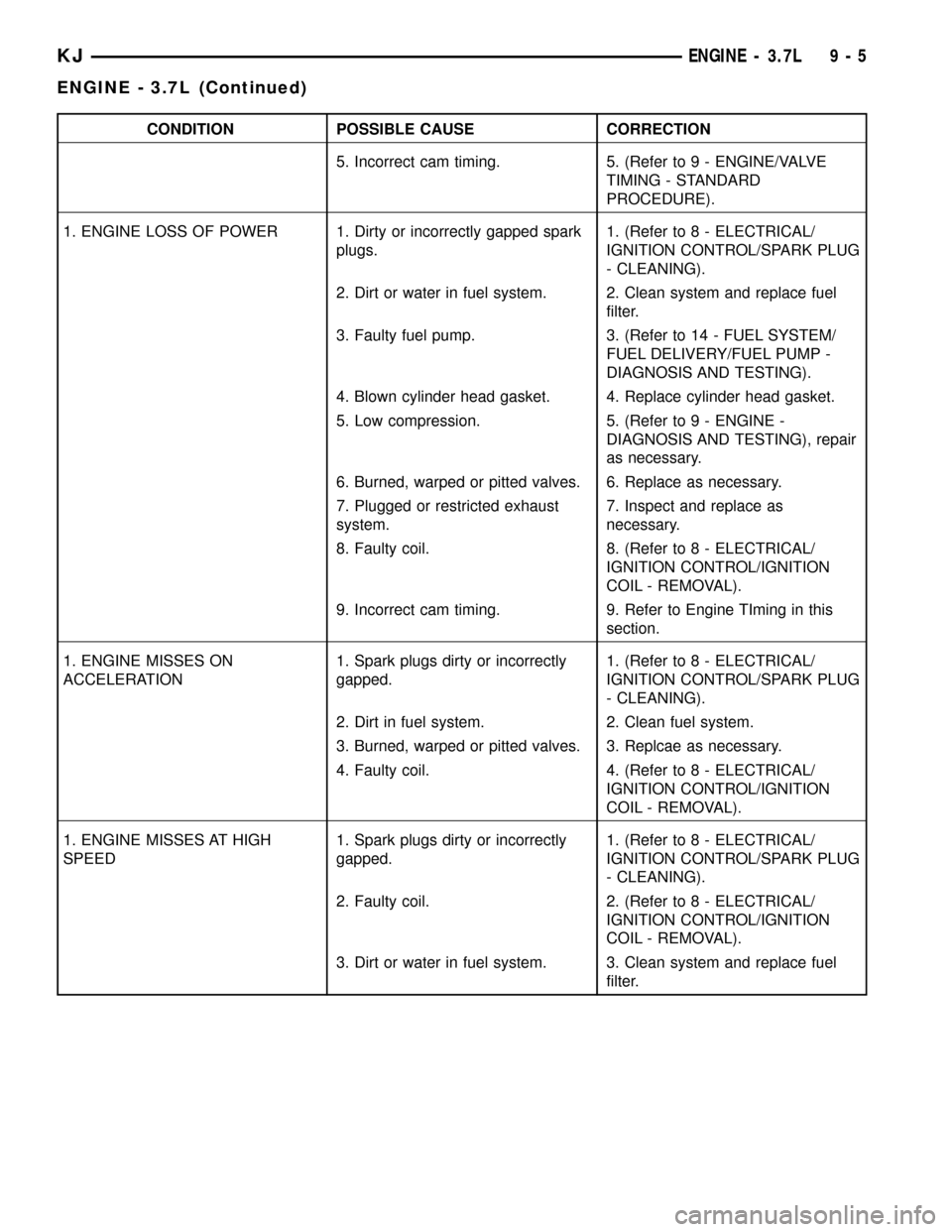
CONDITION POSSIBLE CAUSE CORRECTION
5. Incorrect cam timing. 5. (Refer to 9 - ENGINE/VALVE
TIMING - STANDARD
PROCEDURE).
1. ENGINE LOSS OF POWER 1. Dirty or incorrectly gapped spark
plugs.1. (Refer to 8 - ELECTRICAL/
IGNITION CONTROL/SPARK PLUG
- CLEANING).
2. Dirt or water in fuel system. 2. Clean system and replace fuel
filter.
3. Faulty fuel pump. 3. (Refer to 14 - FUEL SYSTEM/
FUEL DELIVERY/FUEL PUMP -
DIAGNOSIS AND TESTING).
4. Blown cylinder head gasket. 4. Replace cylinder head gasket.
5. Low compression. 5. (Refer to 9 - ENGINE -
DIAGNOSIS AND TESTING), repair
as necessary.
6. Burned, warped or pitted valves. 6. Replace as necessary.
7. Plugged or restricted exhaust
system.7. Inspect and replace as
necessary.
8. Faulty coil. 8. (Refer to 8 - ELECTRICAL/
IGNITION CONTROL/IGNITION
COIL - REMOVAL).
9. Incorrect cam timing. 9. Refer to Engine TIming in this
section.
1. ENGINE MISSES ON
ACCELERATION1. Spark plugs dirty or incorrectly
gapped.1. (Refer to 8 - ELECTRICAL/
IGNITION CONTROL/SPARK PLUG
- CLEANING).
2. Dirt in fuel system. 2. Clean fuel system.
3. Burned, warped or pitted valves. 3. Replcae as necessary.
4. Faulty coil. 4. (Refer to 8 - ELECTRICAL/
IGNITION CONTROL/IGNITION
COIL - REMOVAL).
1. ENGINE MISSES AT HIGH
SPEED1. Spark plugs dirty or incorrectly
gapped.1. (Refer to 8 - ELECTRICAL/
IGNITION CONTROL/SPARK PLUG
- CLEANING).
2. Faulty coil. 2. (Refer to 8 - ELECTRICAL/
IGNITION CONTROL/IGNITION
COIL - REMOVAL).
3. Dirt or water in fuel system. 3. Clean system and replace fuel
filter.
KJENGINE - 3.7L 9 - 5
ENGINE - 3.7L (Continued)
Page 1224 of 1803

CYLINDER COMBUSTION PRESSURE LEAKAGE DIAGNOSIS CHART
CONDITION POSSIBLE CAUSE CORRECTION
AIR ESCAPES THROUGH
THROTTLE BODYIntake valve bent, burnt, or not
seated properlyInspect valve and valve seat.
Reface or replace, as necessary.
Inspect valve springs. Replace as
necessary.
AIR ESCAPES THROUGH
TAILPIPEExhaust valve bent, burnt, or not
seated properlyInspect valve and valve seat.
Reface or replace, as necessary.
Inspect valve springs. Replace as
necessary.
AIR ESCAPES THROUGH
RADIATORHead gasket leaking or cracked
cylinder head or blockRemove cylinder head and inspect.
Replace defective part
MORE THAN 50% LEAKAGE
FROM ADJACENT CYLINDERSHead gasket leaking or crack in
cylinder head or block between
adjacent cylindersRemove cylinder head and inspect.
Replace gasket, head, or block as
necessary
MORE THAN 25% LEAKAGE AND
AIR ESCAPES THROUGH OIL
FILLER CAP OPENING ONLYStuck or broken piston rings;
cracked piston; worn rings and/or
cylinder wallInspect for broken rings or piston.
Measure ring gap and cylinder
diameter, taper and out-of-round.
Replace defective part as necessary
STANDARD PROCEDURE
STANDARD PROCEDURE - ENGINE GASKET
SURFACE PREPARATION
To ensure engine gasket sealing, proper surface
preparation must be performed, especially with the
use of aluminum engine components and multi-layer
steel cylinder head gaskets.
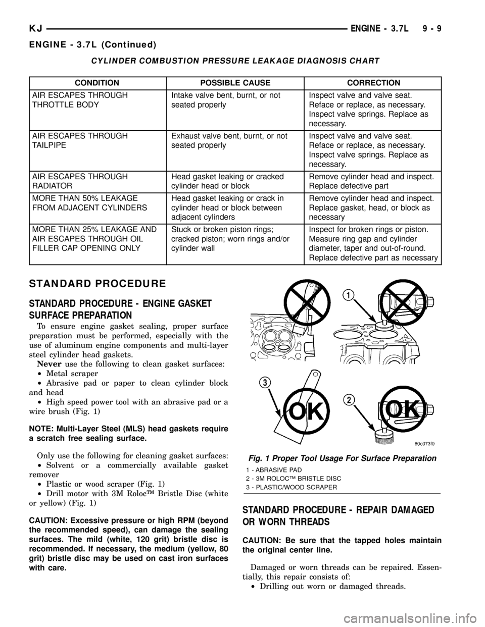
Neveruse the following to clean gasket surfaces:
²Metal scraper
²Abrasive pad or paper to clean cylinder block
and head
²High speed power tool with an abrasive pad or a
wire brush (Fig. 1)
NOTE: Multi-Layer Steel (MLS) head gaskets require
a scratch free sealing surface.
Only use the following for cleaning gasket surfaces:
²Solvent or a commercially available gasket
remover
²Plastic or wood scraper (Fig. 1)
²Drill motor with 3M RolocŸ Bristle Disc (white
or yellow) (Fig. 1)
CAUTION: Excessive pressure or high RPM (beyond
the recommended speed), can damage the sealing
surfaces. The mild (white, 120 grit) bristle disc is
recommended. If necessary, the medium (yellow, 80
grit) bristle disc may be used on cast iron surfaces
with care.
STANDARD PROCEDURE - REPAIR DAMAGED
OR WORN THREADS
CAUTION: Be sure that the tapped holes maintain
the original center line.
Damaged or worn threads can be repaired. Essen-
tially, this repair consists of:
²Drilling out worn or damaged threads.
Fig. 1 Proper Tool Usage For Surface Preparation
1 - ABRASIVE PAD
2 - 3M ROLOCŸ BRISTLE DISC
3 - PLASTIC/WOOD SCRAPER
KJENGINE - 3.7L 9 - 9
ENGINE - 3.7L (Continued)
Page 1275 of 1803

DIAGNOSIS AND TESTING
DIAGNOSIS AND TESTING - ENGINE OIL LEAK
Begin with a thorough visual inspection of the
engine, particularly at the area of the suspected leak.
If an oil leak source is not readily identifiable, the
following steps should be followed:
(1) Do not clean or degrease the engine at this
time because some solvents may cause rubber to
swell, temporarily stopping the leak.
(2) Add an oil soluble dye (use as recommended by
manufacturer). Start the engine and let idle for
approximately 15 minutes. Check the oil dipstick to
make sure the dye is thoroughly mixed as indicated
with a bright yellow color under a black light.
(3) Using a black light, inspect the entire engine
for fluorescent dye, particularly at the suspected area
of oil leak. If the oil leak is found and identified,
repair per service manual instructions.
(4) If dye is not observed, drive the vehicle at var-
ious speeds for approximately 24km (15 miles), and
repeat inspection.If the oil leak source is not pos-
itively identified at this time, proceed with the air
leak detection test method.
Air Leak Detection Test Method
(1) Disconnect the breather cap to air cleaner hose
at the breather cap end. Cap or plug breather cap
nipple.
(2) Remove the PCV valve from the cylinder head
cover. Cap or plug the PCV valve grommet.
(3) Attach an air hose with pressure gauge and
regulator to the dipstick tube.
CAUTION: Do not subject the engine assembly to
more than 20.6 kpa (3 PSI) of test pressure.
(4) Gradually apply air pressure from 1 psi to 2.5
psi maximum while applying soapy water at the sus-
pected source. Adjust the regulator to the suitable
test pressure that provide the best bubbles which
will pinpoint the leak source. If the oil leak is
detected and identified, repair per service manual
procedures.
(5) If the leakage occurs at the rear oil seal area,
refer to the section, Inspection for Rear Seal Area
Leak.
(6) If no leaks are detected, turn off the air supply
and remove the air hose and all plugs and caps.
Install the PCV valve and breather cap hose.
(7) Clean the oil off the suspect oil leak area using
a suitable solvent. Drive the vehicle at various
speeds approximately 24 km (15 miles). Inspect the
engine for signs of an oil leak by using a black light.
INSPECTION FOR REAR SEAL AREA LEAKS
Since it is sometimes difficult to determine the
source of an oil leak in the rear seal area of the
engine, a more involved inspection is necessary. The
following steps should be followed to help pinpoint
the source of the leak.
If the leakage occurs at the crankshaft rear oil seal
area:
(1) Disconnect the battery.
(2) Raise the vehicle.
(3) Remove torque converter or clutch housing
cover and inspect rear of block for evidence of oil.
Use a black light to check for the oil leak:
(a) Circular spray pattern generally indicates
seal leakage or crankshaft damage.
(b) Where leakage tends to run straight down,
possible causes are a porous block, camshaft bore
cup plugs oil galley pipe plugs, oil filter runoff, and
main bearing cap to cylinder block mating sur-
faces.
(4) If no leaks are detected, pressurize the crank-
case as outlined in the, Inspection (Engine oil Leaks
in general)
CAUTION: Do not exceed 20.6 kPa (3 psi).
(5) If the leak is not detected, very slowly turn the
crankshaft and watch for leakage. If a leak is
detected between the crankshaft and seal while
slowly turning the crankshaft, it is possible the
crankshaft seal surface is damaged. The seal area on
the crankshaft could have minor nicks or scratches
that can be polished out with emery cloth.
CAUTION: Use extreme caution when crankshaft
polishing is necessary to remove minor nicks and
scratches. The crankshaft seal flange is especially
machined to complement the function of the rear oil
seal.
(6) For bubbles that remain steady with shaft
rotation, no further inspection can be done until dis-
assembled.
DIAGNOSIS AND TESTING - ENGINE OIL
PRESSURE
(1) Remove oil pressure sending unit (Fig. 70)and
install gauge assembly C-3292.
(2) Run engine until thermostat opens.
(3) Oil Pressure:
²Curb IdleÐ25 Kpa (4 psi) minimum
²3000 rpmÐ170 - 550 KPa (25 - 80 psi)
(4) If oil pressure is 0 at idle, shut off engine.
Check for a clogged oil pick-up screen or a pressure
relief valve stuck open.
9 - 60 ENGINE - 3.7LKJ
LUBRICATION (Continued)