2002 JEEP LIBERTY Engine 3.7L
[x] Cancel search: Engine 3.7LPage 1296 of 1803
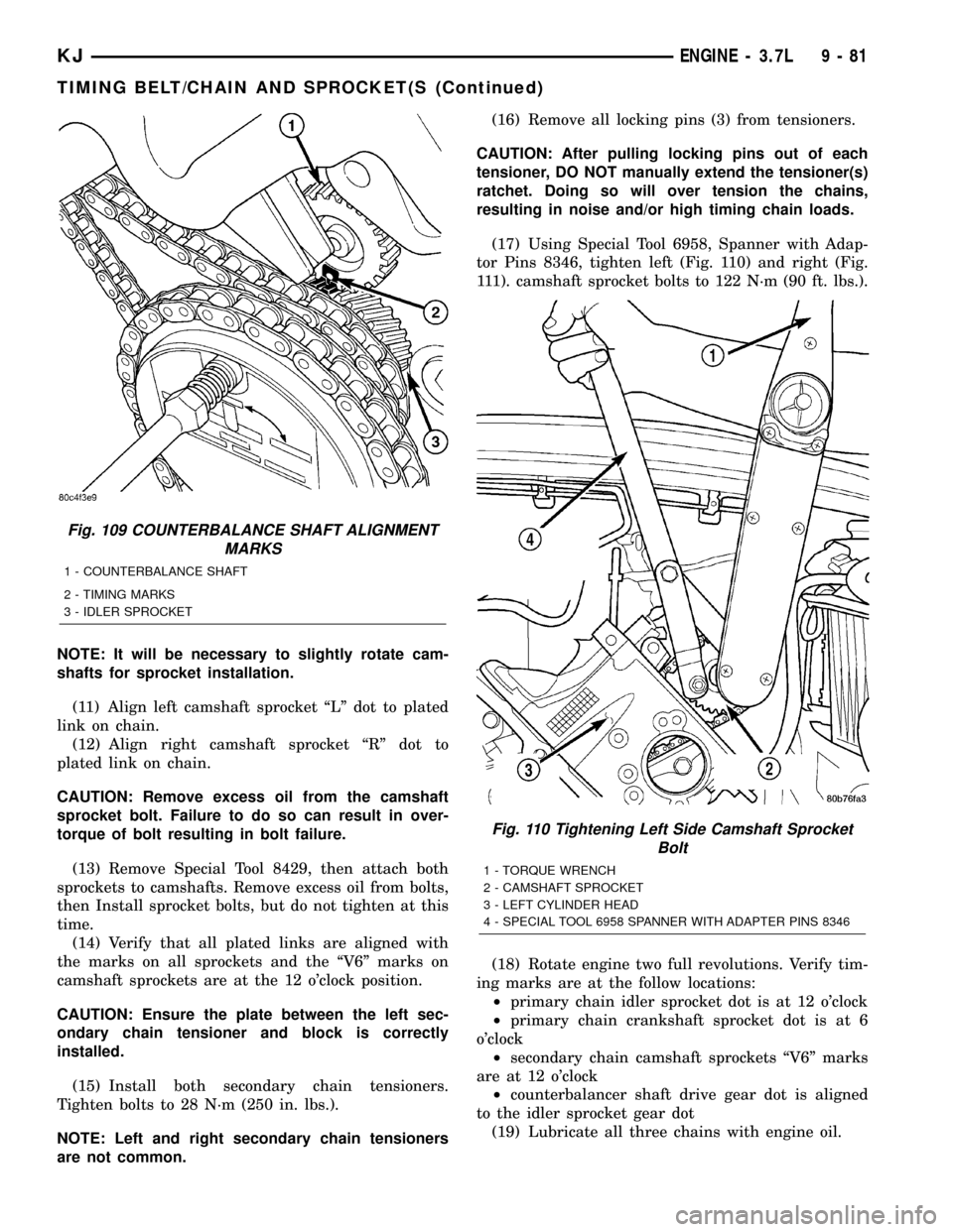
NOTE: It will be necessary to slightly rotate cam-
shafts for sprocket installation.
(11) Align left camshaft sprocket ªLº dot to plated
link on chain.
(12) Align right camshaft sprocket ªRº dot to
plated link on chain.
CAUTION: Remove excess oil from the camshaft
sprocket bolt. Failure to do so can result in over-
torque of bolt resulting in bolt failure.
(13) Remove Special Tool 8429, then attach both
sprockets to camshafts. Remove excess oil from bolts,
then Install sprocket bolts, but do not tighten at this
time.
(14) Verify that all plated links are aligned with
the marks on all sprockets and the ªV6º marks on
camshaft sprockets are at the 12 o'clock position.
CAUTION: Ensure the plate between the left sec-
ondary chain tensioner and block is correctly
installed.
(15) Install both secondary chain tensioners.
Tighten bolts to 28 N´m (250 in. lbs.).
NOTE: Left and right secondary chain tensioners
are not common.(16) Remove all locking pins (3) from tensioners.
CAUTION: After pulling locking pins out of each
tensioner, DO NOT manually extend the tensioner(s)
ratchet. Doing so will over tension the chains,
resulting in noise and/or high timing chain loads.
(17) Using Special Tool 6958, Spanner with Adap-
tor Pins 8346, tighten left (Fig. 110) and right (Fig.
111). camshaft sprocket bolts to 122 N´m (90 ft. lbs.).
(18) Rotate engine two full revolutions. Verify tim-
ing marks are at the follow locations:
²primary chain idler sprocket dot is at 12 o'clock
²primary chain crankshaft sprocket dot is at 6
o'clock
²secondary chain camshaft sprockets ªV6º marks
are at 12 o'clock
²counterbalancer shaft drive gear dot is aligned
to the idler sprocket gear dot
(19) Lubricate all three chains with engine oil.
Fig. 109 COUNTERBALANCE SHAFT ALIGNMENT
MARKS
1 - COUNTERBALANCE SHAFT
2 - TIMING MARKS
3 - IDLER SPROCKET
Fig. 110 Tightening Left Side Camshaft Sprocket
Bolt
1 - TORQUE WRENCH
2 - CAMSHAFT SPROCKET
3 - LEFT CYLINDER HEAD
4 - SPECIAL TOOL 6958 SPANNER WITH ADAPTER PINS 8346
KJENGINE - 3.7L 9 - 81
TIMING BELT/CHAIN AND SPROCKET(S (Continued)
Page 1297 of 1803
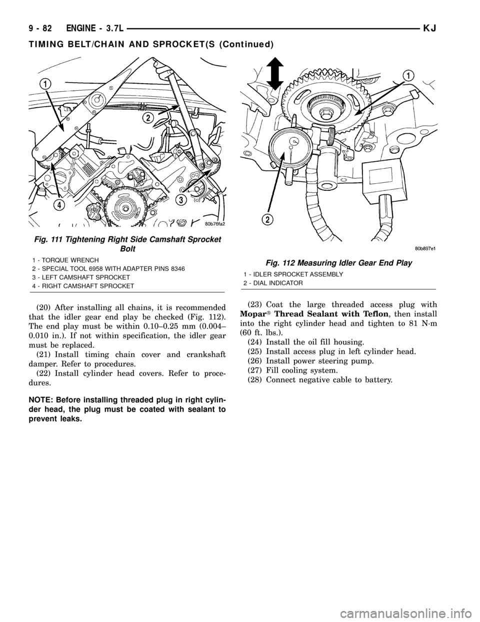
(20) After installing all chains, it is recommended
that the idler gear end play be checked (Fig. 112).
The end play must be within 0.10±0.25 mm (0.004±
0.010 in.). If not within specification, the idler gear
must be replaced.
(21) Install timing chain cover and crankshaft
damper. Refer to procedures.
(22) Install cylinder head covers. Refer to proce-
dures.
NOTE: Before installing threaded plug in right cylin-
der head, the plug must be coated with sealant to
prevent leaks.(23) Coat the large threaded access plug with
MopartThread Sealant with Teflon, then install
into the right cylinder head and tighten to 81 N´m
(60 ft. lbs.).
(24) Install the oil fill housing.
(25) Install access plug in left cylinder head.
(26) Install power steering pump.
(27) Fill cooling system.
(28) Connect negative cable to battery.
Fig. 111 Tightening Right Side Camshaft Sprocket
Bolt
1 - TORQUE WRENCH
2 - SPECIAL TOOL 6958 WITH ADAPTER PINS 8346
3 - LEFT CAMSHAFT SPROCKET
4 - RIGHT CAMSHAFT SPROCKETFig. 112 Measuring Idler Gear End Play
1 - IDLER SPROCKET ASSEMBLY
2 - DIAL INDICATOR
9 - 82 ENGINE - 3.7LKJ
TIMING BELT/CHAIN AND SPROCKET(S (Continued)
Page 1342 of 1803
REAR MOUNT
REMOVAL
NOTE: A resilient rubber cushion supports the
transmission at the rear between the transmission
extension housing and the rear support crossmem-
ber or skid plate.
(1) Disconnect negative cable from battery.
(2) Raise the vehicle and support the transmission.
(3) Remove the nuts holding the support cushion
to the crossmember. Remove the crossmember.
MANUAL TRANSMISSION
a. Remove the support cushion nuts and remove
the cushion.
b. Remove the transmission support bracket bolts
and remove the bracket from the transmission.
AUTOMATIC TRANSMISSION
c. Remove the support cushion bolts and remove
the cushion and the support bracket from the trans-
mission (4WD) or from the adaptor bracket (2WD).
d. On 2WD vehicles, remove the bolts holding the
transmission support adaptor bracket to the trans-
mission. Remove the adaptor bracket.
INSTALLATION
MANUAL TRANSMISSION:
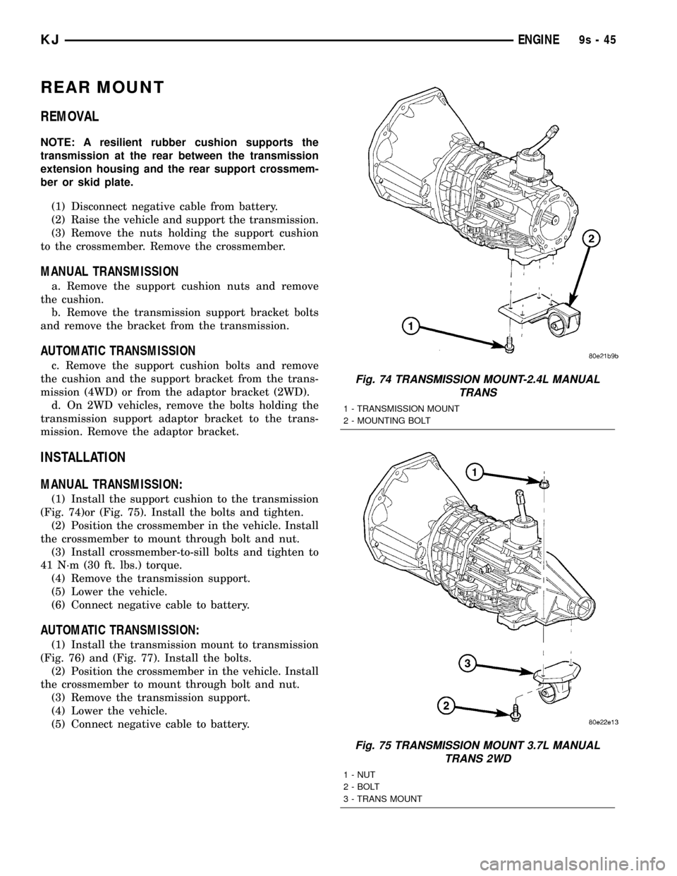
(1) Install the support cushion to the transmission
(Fig. 74)or (Fig. 75). Install the bolts and tighten.
(2) Position the crossmember in the vehicle. Install
the crossmember to mount through bolt and nut.
(3) Install crossmember-to-sill bolts and tighten to
41 N´m (30 ft. lbs.) torque.
(4) Remove the transmission support.
(5) Lower the vehicle.
(6) Connect negative cable to battery.
AUTOMATIC TRANSMISSION:
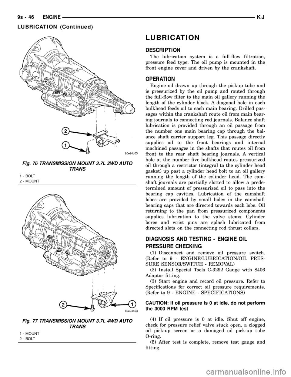
(1) Install the transmission mount to transmission
(Fig. 76) and (Fig. 77). Install the bolts.
(2) Position the crossmember in the vehicle. Install
the crossmember to mount through bolt and nut.
(3) Remove the transmission support.
(4) Lower the vehicle.
(5) Connect negative cable to battery.
Fig. 74 TRANSMISSION MOUNT-2.4L MANUAL
TRANS
1 - TRANSMISSION MOUNT
2 - MOUNTING BOLT
Fig. 75 TRANSMISSION MOUNT 3.7L MANUAL
TRANS 2WD
1 - NUT
2 - BOLT
3 - TRANS MOUNT
KJENGINE9s-45
Page 1343 of 1803
LUBRICATION
DESCRIPTION
The lubrication system is a full-flow filtration,
pressure feed type. The oil pump is mounted in the
front engine cover and driven by the crankshaft.
OPERATION
Engine oil drawn up through the pickup tube and
is pressurized by the oil pump and routed through
the full-flow filter to the main oil gallery running the
length of the cylinder block. A diagonal hole in each
bulkhead feeds oil to each main bearing. Drilled pas-
sages within the crankshaft route oil from main bear-
ing journals to connecting rod journals. Balance shaft
lubrication is provided through an oil passage from
the number one main bearing cap through the bal-
ance shaft carrier support leg. This passage directly
supplies oil to the front bearings and internal
machined passages in the shafts that routes oil from
front to the rear shaft bearing journals. A vertical
hole at the number five bulkhead routes pressurized
oil through a restrictor (integral to the cylinder head
gasket) up past a cylinder head bolt to an oil gallery
running the length of the cylinder head. The cam-
shaft journals are partially slotted to allow a prede-
termined amount of pressurized oil to pass into the
bearing cap cavities. Lubrication of the camshaft
lobes are provided by small holes in the camshaft
bearing caps that are directed towards each lobe. Oil
returning to the pan from pressurized components
supplies lubrication to the valve stems. Cylinder
bores and wrist pins are splash lubricated from
directed slots on the connecting rod thrust collars.
DIAGNOSIS AND TESTING - ENGINE OIL
PRESSURE CHECKING
(1) Disconnect and remove oil pressure switch.
(Refer to 9 - ENGINE/LUBRICATION/OIL PRES-
SURE SENSOR/SWITCH - REMOVAL)
(2) Install Special Tools C-3292 Gauge with 8406
Adaptor fitting.
(3) Start engine and record oil pressure. Refer to
Specifications for correct oil pressure requirements.
(Refer to 9 - ENGINE - SPECIFICATIONS)
CAUTION: If oil pressure is 0 at idle, do not perform
the 3000 RPM test
(4) If oil pressure is 0 at idle. Shut off engine,
check for pressure relief valve stuck open, a clogged
oil pick-up screen or a damaged oil pick-up tube
O-ring.
(5) After test is complete, remove test gauge and
fitting.
Fig. 76 TRANSMISSION MOUNT 3.7L 2WD AUTO
TRANS
1 - BOLT
2 - MOUNT
Fig. 77 TRANSMISSION MOUNT 3.7L 4WD AUTO
TRANS
1 - MOUNT
2 - BOLT
9s - 46 ENGINEKJ
LUBRICATION (Continued)
Page 1365 of 1803
WARNING: THE NORMAL OPERATING TEMPERA-
TURE OF THE EXHAUST SYSTEM IS VERY HIGH.
THEREFORE, NEVER WORK AROUND OR ATTEMPT
TO SERVICE ANY PART OF THE EXHAUST SYSTEM
UNTIL IT IS COOLED. SPECIAL CARE SHOULD BE
TAKEN WHEN WORKING NEAR THE CATALYTIC
CONVERTER. THE TEMPERATURE OF THE CON-
VERTER RISES TO A HIGH LEVEL AFTER A SHORT
PERIOD OF ENGINE OPERATION TIME.
(1) Install the crossove pipe into the hanger insu-
lator.
(2) Install and torque the fasteners in the cross-
over pipe to the left and right catalytic converter con-
nection.
(3) Install and torque the retaining fasteners hold-
ing the crossover pipe to exhaust pipe.
(4) Lower vehicle..
(5) Start engine and check for leaks.
HEAT SHIELDS
DESCRIPTION
Heat shields are needed to protect both the vehicle
and the environment from the high temperatures
developed by the catalytic converter. The catalytic
converter releases additional heat into the exhaustsystem. Under severe operating conditions, the tem-
perature increases in the area of the converter. Such
conditions can exist when the engine misfires or oth-
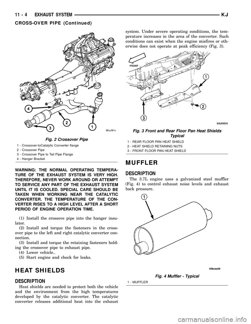
erwise does not operate at peak efficiency (Fig. 3).
MUFFLER
DESCRIPTION
The 3.7L engine uses a galvanized steel muffler
(Fig. 4) to control exhaust noise levels and exhaust
back pressure.
Fig. 2 Crossover Pipe
1 - Crossover-toCatalytic Converter flange
2 - Crossover Pipe
3 - Crossover Pipe to Tail Pipe Flange
4 - Hanger Bracket
Fig. 3 Front and Rear Floor Pan Heat Shields
Typical
1 - REAR FLOOR PAN HEAT SHIELD
2 - HEAT SHIELD RETAINING NUTS
3 - FRONT FLOOR PAN HEAT SHIELD
Fig. 4 Muffler - Typical
1 - MUFFLER
11 - 4 EXHAUST SYSTEMKJ
CROSS-OVER PIPE (Continued)
Page 1370 of 1803
2.4L ENGINES
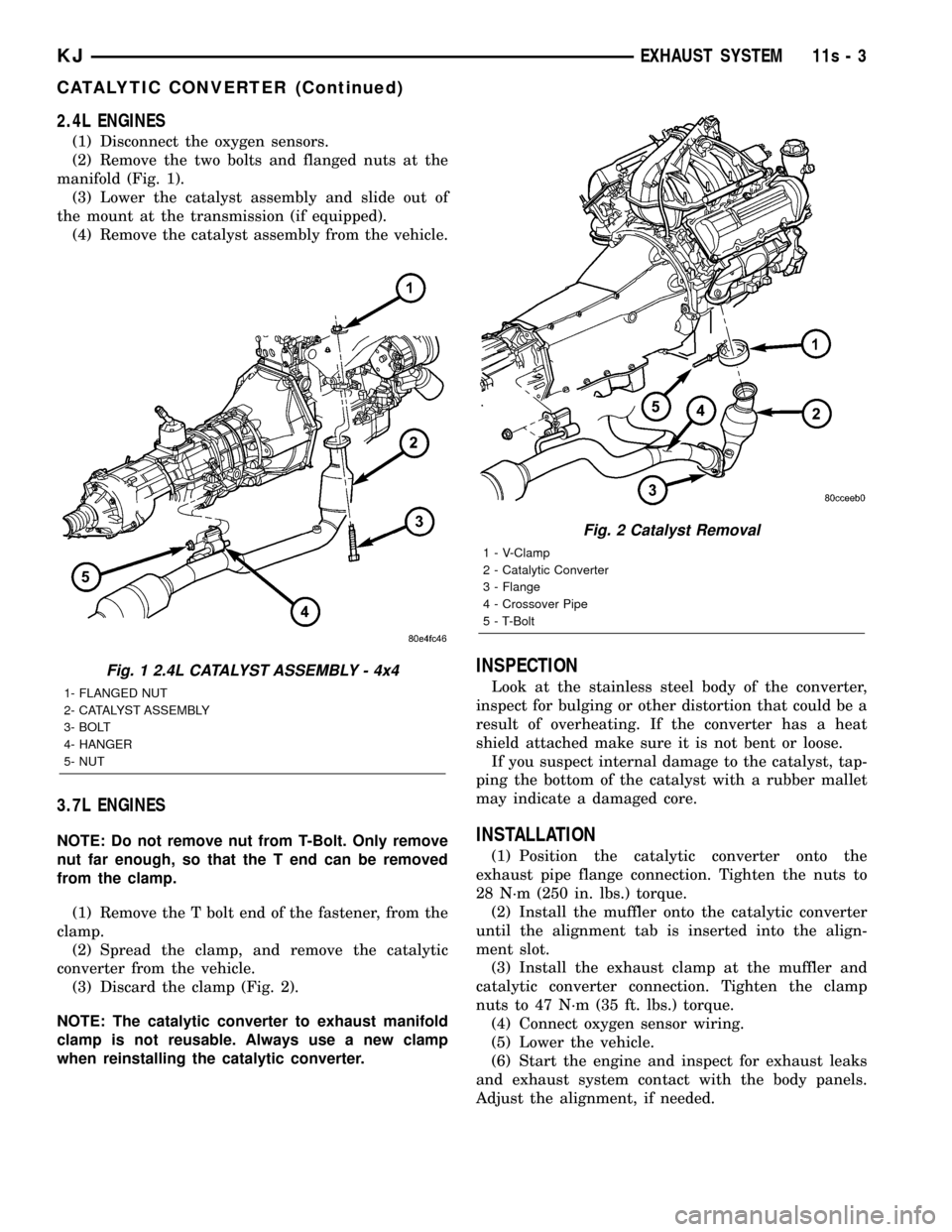
(1) Disconnect the oxygen sensors.
(2) Remove the two bolts and flanged nuts at the
manifold (Fig. 1).
(3) Lower the catalyst assembly and slide out of
the mount at the transmission (if equipped).
(4) Remove the catalyst assembly from the vehicle.
3.7L ENGINES
NOTE: Do not remove nut from T-Bolt. Only remove
nut far enough, so that the T end can be removed
from the clamp.
(1) Remove the T bolt end of the fastener, from the
clamp.
(2) Spread the clamp, and remove the catalytic
converter from the vehicle.
(3) Discard the clamp (Fig. 2).
NOTE: The catalytic converter to exhaust manifold
clamp is not reusable. Always use a new clamp
when reinstalling the catalytic converter.
INSPECTION
Look at the stainless steel body of the converter,
inspect for bulging or other distortion that could be a
result of overheating. If the converter has a heat
shield attached make sure it is not bent or loose.
If you suspect internal damage to the catalyst, tap-
ping the bottom of the catalyst with a rubber mallet
may indicate a damaged core.
INSTALLATION
(1) Position the catalytic converter onto the
exhaust pipe flange connection. Tighten the nuts to
28 N´m (250 in. lbs.) torque.
(2) Install the muffler onto the catalytic converter
until the alignment tab is inserted into the align-
ment slot.
(3) Install the exhaust clamp at the muffler and
catalytic converter connection. Tighten the clamp
nuts to 47 N´m (35 ft. lbs.) torque.
(4) Connect oxygen sensor wiring.
(5) Lower the vehicle.
(6) Start the engine and inspect for exhaust leaks
and exhaust system contact with the body panels.
Adjust the alignment, if needed.
Fig. 1 2.4L CATALYST ASSEMBLY - 4x4
1- FLANGED NUT
2- CATALYST ASSEMBLY
3- BOLT
4- HANGER
5- NUT
Fig. 2 Catalyst Removal
1 - V-Clamp
2 - Catalytic Converter
3 - Flange
4 - Crossover Pipe
5 - T-Bolt
KJEXHAUST SYSTEM 11s - 3
CATALYTIC CONVERTER (Continued)
Page 1371 of 1803
CROSS-OVER PIPE
REMOVAL
WARNING: IF TORCHES ARE USED WHEN WORK-
ING ON THE EXHAUST SYSTEM, DO NOT ALLOW
THE FLAME NEAR THE FUEL LINES.
WARNING: THE NORMAL OPERATING TEMPERA-
TURE OF THE EXHAUST SYSTEM IS VERY HIGH.
THEREFORE, NEVER WORK AROUND OR ATTEMPT
TO SERVICE ANY PART OF THE EXHAUST SYSTEM
UNTIL IT IS COOLED. SPECIAL CARE SHOULD BE
TAKEN WHEN WORKING NEAR THE CATALYTIC
CONVERTER. THE TEMPERATURE OF THE CON-
VERTER RISES TO A HIGH LEVEL AFTER A SHORT
PERIOD OF ENGINE OPERATION TIME.
(1) Raise and support the vehicle.
(2) Saturate the bolts and nuts with lubricant.
Allow 5 minutes for penetration.
(3) Remove the retaining fasteners holding cross-
over pipe to exhaust pipe.
(4) Remove the fasteners from the crossover pipe
to the catalytic converter connection.
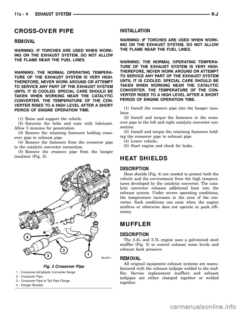
(5) Remove the crossove pipe from the hanger
insulator (Fig. 3).
INSTALLATION
WARNING: IF TORCHES ARE USED WHEN WORK-
ING ON THE EXHAUST SYSTEM, DO NOT ALLOW
THE FLAME NEAR THE FUEL LINES.
WARNING: THE NORMAL OPERATING TEMPERA-
TURE OF THE EXHAUST SYSTEM IS VERY HIGH.
THEREFORE, NEVER WORK AROUND OR ATTEMPT
TO SERVICE ANY PART OF THE EXHAUST SYSTEM
UNTIL IT IS COOLED. SPECIAL CARE SHOULD BE
TAKEN WHEN WORKING NEAR THE CATALYTIC
CONVERTER. THE TEMPERATURE OF THE CON-
VERTER RISES TO A HIGH LEVEL AFTER A SHORT
PERIOD OF ENGINE OPERATION TIME.
(1) Install the crossove pipe into the hanger insu-
lator.
(2) Install and torque the fasteners in the cross-
over pipe to the left and right catalytic converter con-
nection.
(3) Install and torque the retaining fasteners hold-
ing the crossover pipe to exhaust pipe.
(4) Lower vehicle..
(5) Start engine and check for leaks.
HEAT SHIELDS
DESCRIPTION
Heat shields (Fig. 4) are needed to protect both the
vehicle and the environment from the high tempera-
tures developed by the catalytic converter. The cata-
lytic converter releases additional heat into the
exhaust system. Under severe operating conditions,
the temperature increases in the area of the con-
verter. Such conditions can exist when the engine
misfires or otherwise does not operate at peak effi-
ciency.
MUFFLER
DESCRIPTION
The 2.4L and 3.7L engine uses a galvanized steel
muffler (Fig. 5) to control exhaust noise levels and
exhaust back pressure.
REMOVAL
All original equipment exhaust systems are manu-
factured with the exhaust tailpipe welded to the muf-
fler. Service replacement mufflers and exhaust
tailpipes are either clamped together or welded
together.Fig. 3 Crossover Pipe
1 - Crossover-toCatalytic Converter flange
2 - Crossover Pipe
3 - Crossover Pipe to Tail Pipe Flange
4 - Hanger Bracket
11s - 4 EXHAUST SYSTEMKJ
Page 1387 of 1803
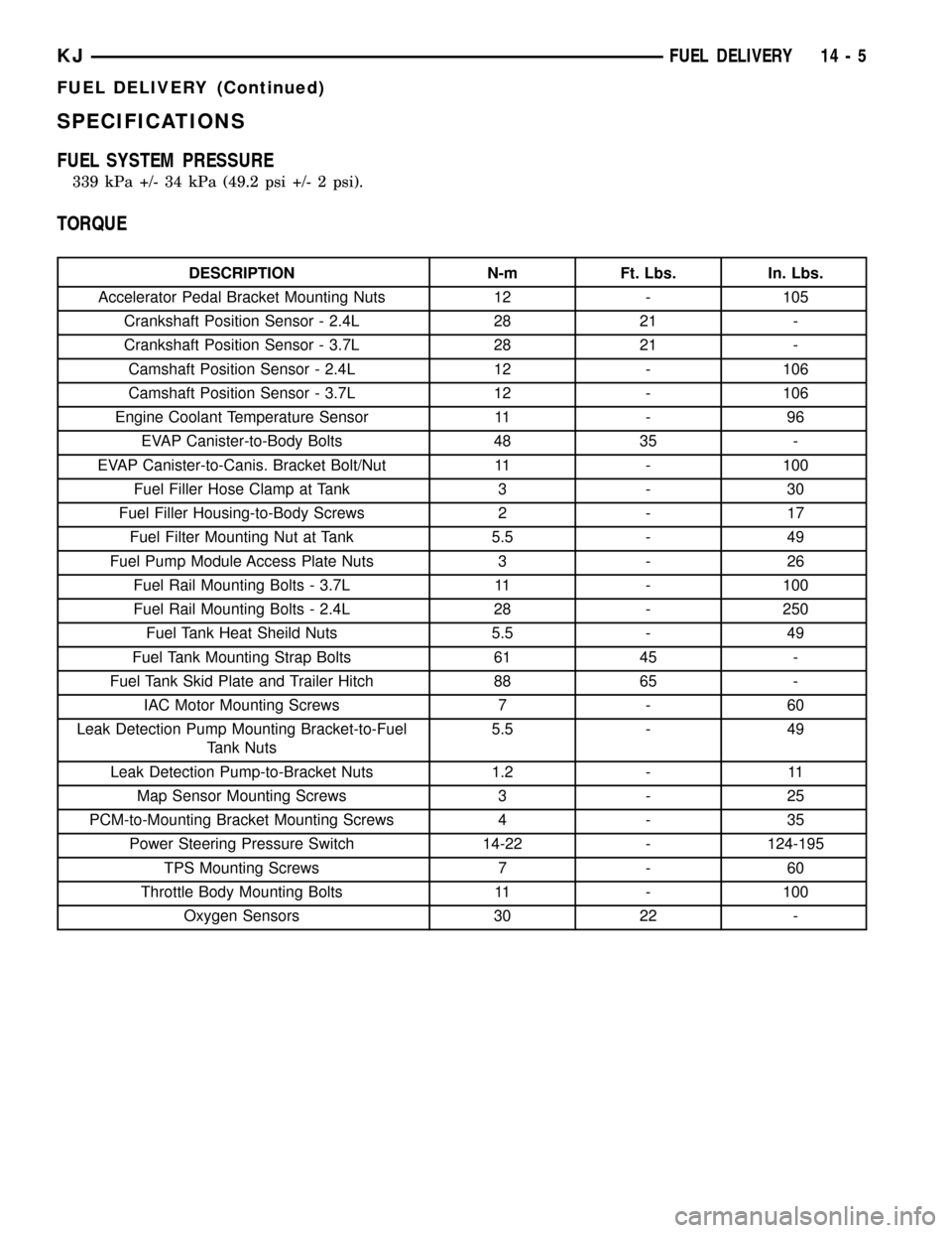
SPECIFICATIONS
FUEL SYSTEM PRESSURE
339 kPa +/- 34 kPa (49.2 psi +/- 2 psi).
TORQUE
DESCRIPTION N-m Ft. Lbs. In. Lbs.
Accelerator Pedal Bracket Mounting Nuts 12 - 105
Crankshaft Position Sensor - 2.4L 28 21 -
Crankshaft Position Sensor - 3.7L 28 21 -
Camshaft Position Sensor - 2.4L 12 - 106
Camshaft Position Sensor - 3.7L 12 - 106
Engine Coolant Temperature Sensor 11 - 96
EVAP Canister-to-Body Bolts 48 35 -
EVAP Canister-to-Canis. Bracket Bolt/Nut 11 - 100
Fuel Filler Hose Clamp at Tank 3 - 30
Fuel Filler Housing-to-Body Screws 2 - 17
Fuel Filter Mounting Nut at Tank 5.5 - 49
Fuel Pump Module Access Plate Nuts 3 - 26
Fuel Rail Mounting Bolts - 3.7L 11 - 100
Fuel Rail Mounting Bolts - 2.4L 28 - 250
Fuel Tank Heat Sheild Nuts 5.5 - 49
Fuel Tank Mounting Strap Bolts 61 45 -
Fuel Tank Skid Plate and Trailer Hitch 88 65 -
IAC Motor Mounting Screws 7 - 60
Leak Detection Pump Mounting Bracket-to-Fuel
Tank Nuts5.5 - 49
Leak Detection Pump-to-Bracket Nuts 1.2 - 11
Map Sensor Mounting Screws 3 - 25
PCM-to-Mounting Bracket Mounting Screws 4 - 35
Power Steering Pressure Switch 14-22 - 124-195
TPS Mounting Screws 7 - 60
Throttle Body Mounting Bolts 11 - 100
Oxygen Sensors 30 22 -
KJFUEL DELIVERY 14 - 5
FUEL DELIVERY (Continued)