2002 JEEP LIBERTY Brake lamp switch
[x] Cancel search: Brake lamp switchPage 1149 of 1803
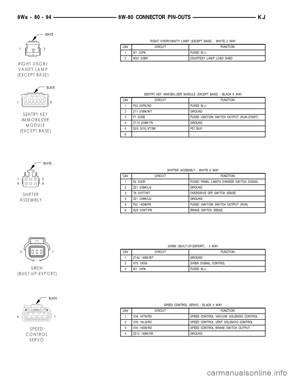
RIGHT VISOR/VANITY LAMP (EXCEPT BASE) - WHITE 2 WAY
CAV CIRCUIT FUNCTION
1 M1 20PK FUSED B(+)
2 M20 20BR COURTESY LAMP LOAD SHED
SENTRY KEY IMMOBILIZER MODULE (EXCEPT BASE) - BLACK 6 WAY
CAV CIRCUIT FUNCTION
1 F33 20PK/RD FUSED B(+)
2 Z11 20BK/WT GROUND
3 F1 20DB FUSED IGNITION SWITCH OUTPUT (RUN-START)
4 Z110 20BK/TN GROUND
5 D25 20YL/VT/BK PCI BUS
6- -
SHIFTER ASSEMBLY - WHITE 6 WAY
CAV CIRCUIT FUNCTION
1 E2 20OR FUSED PANEL LAMPS DIMMER SWITCH SIGNAL
2 Z21 20BK/LG GROUND
3 T6 20VT/WT OVERDRIVE OFF SWITCH SENSE
4 Z21 20BK/LG GROUND
5 F22 18DB/PK FUSED IGNITION SWITCH OUTPUT (RUN)
6 K29 20WT/PK BRAKE SWITCH SENSE
SIREN (BUILT-UP-EXPORT)-3WAY
CAV CIRCUIT FUNCTION
1 Z142 18BK/WT GROUND
2 X75 18DG SIREN SIGNAL CONTROL
3 M1 18PK FUSED B(+)
SPEED CONTROL SERVO - BLACK 4 WAY
CAV CIRCUIT FUNCTION
1 V36 18TN/RD SPEED CONTROL VACUUM SOLENOID CONTROL
2 V35 18LG/RD SPEED CONTROL VENT SOLENOID CONTROL
3 V30 18DB/RD SPEED CONTROL BRAKE SWITCH OUTPUT
4 Z212 18BK/OR GROUND
8Wa - 80 - 94 8W-80 CONNECTOR PIN-OUTSKJ
Page 1151 of 1803
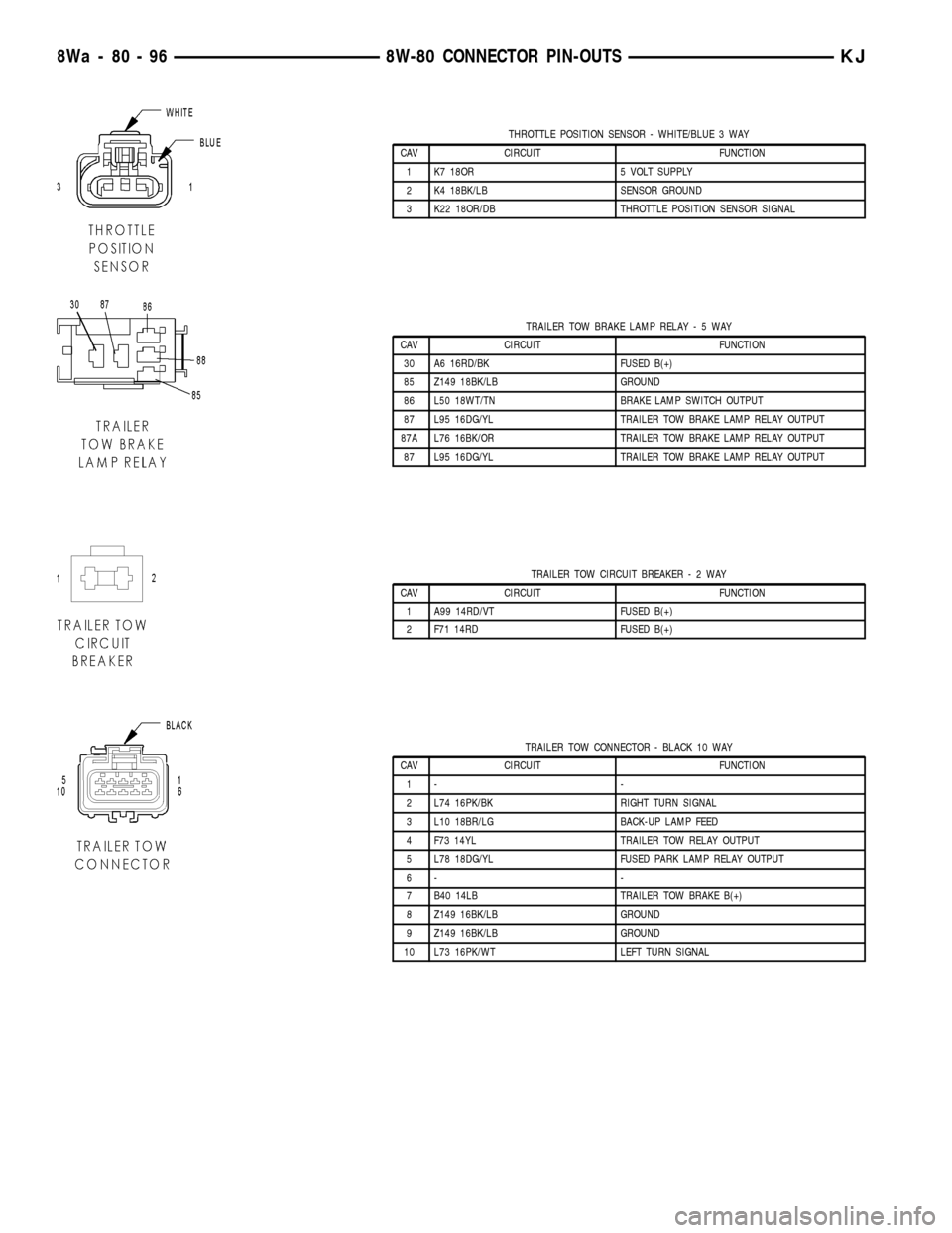
THROTTLE POSITION SENSOR - WHITE/BLUE 3 WAY
CAV CIRCUIT FUNCTION
1 K7 18OR 5 VOLT SUPPLY
2 K4 18BK/LB SENSOR GROUND
3 K22 18OR/DB THROTTLE POSITION SENSOR SIGNAL
TRAILER TOW BRAKE LAMP RELAY-5WAY
CAV CIRCUIT FUNCTION
30 A6 16RD/BK FUSED B(+)
85 Z149 18BK/LB GROUND
86 L50 18WT/TN BRAKE LAMP SWITCH OUTPUT
87 L95 16DG/YL TRAILER TOW BRAKE LAMP RELAY OUTPUT
87A L76 16BK/OR TRAILER TOW BRAKE LAMP RELAY OUTPUT
87 L95 16DG/YL TRAILER TOW BRAKE LAMP RELAY OUTPUT
TRAILER TOW CIRCUIT BREAKER-2WAY
CAV CIRCUIT FUNCTION
1 A99 14RD/VT FUSED B(+)
2 F71 14RD FUSED B(+)
TRAILER TOW CONNECTOR - BLACK 10 WAY
CAV CIRCUIT FUNCTION
1- -
2 L74 16PK/BK RIGHT TURN SIGNAL
3 L10 18BR/LG BACK-UP LAMP FEED
4 F73 14YL TRAILER TOW RELAY OUTPUT
5 L78 18DG/YL FUSED PARK LAMP RELAY OUTPUT
6- -
7 B40 14LB TRAILER TOW BRAKE B(+)
8 Z149 16BK/LB GROUND
9 Z149 16BK/LB GROUND
10 L73 16PK/WT LEFT TURN SIGNAL
8Wa - 80 - 96 8W-80 CONNECTOR PIN-OUTSKJ
Page 1152 of 1803
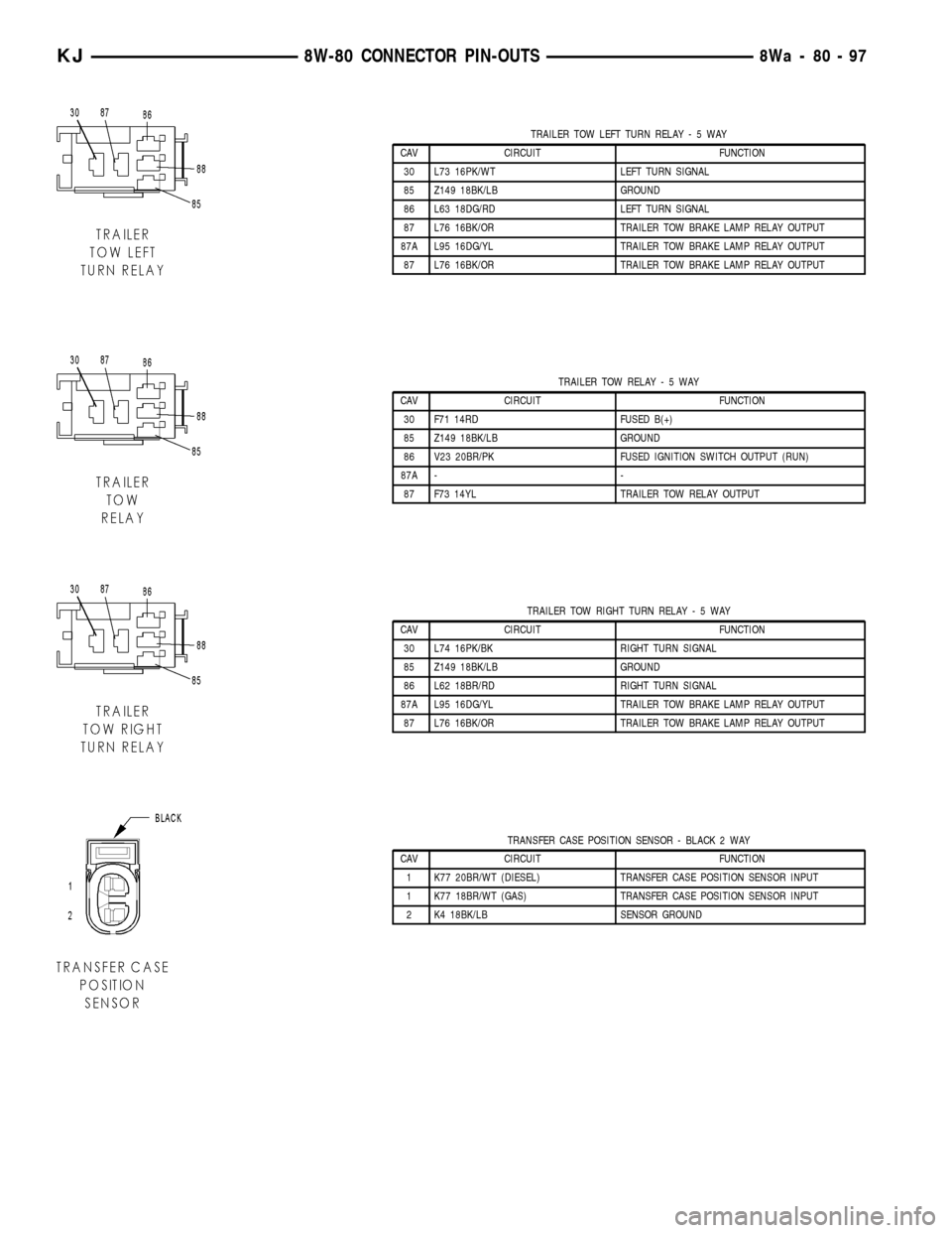
TRAILER TOW LEFT TURN RELAY-5WAY
CAV CIRCUIT FUNCTION
30 L73 16PK/WT LEFT TURN SIGNAL
85 Z149 18BK/LB GROUND
86 L63 18DG/RD LEFT TURN SIGNAL
87 L76 16BK/OR TRAILER TOW BRAKE LAMP RELAY OUTPUT
87A L95 16DG/YL TRAILER TOW BRAKE LAMP RELAY OUTPUT
87 L76 16BK/OR TRAILER TOW BRAKE LAMP RELAY OUTPUT
TRAILER TOW RELAY-5WAY
CAV CIRCUIT FUNCTION
30 F71 14RD FUSED B(+)
85 Z149 18BK/LB GROUND
86 V23 20BR/PK FUSED IGNITION SWITCH OUTPUT (RUN)
87A - -
87 F73 14YL TRAILER TOW RELAY OUTPUT
TRAILER TOW RIGHT TURN RELAY-5WAY
CAV CIRCUIT FUNCTION
30 L74 16PK/BK RIGHT TURN SIGNAL
85 Z149 18BK/LB GROUND
86 L62 18BR/RD RIGHT TURN SIGNAL
87A L95 16DG/YL TRAILER TOW BRAKE LAMP RELAY OUTPUT
87 L76 16BK/OR TRAILER TOW BRAKE LAMP RELAY OUTPUT
TRANSFER CASE POSITION SENSOR - BLACK 2 WAY
CAV CIRCUIT FUNCTION
1 K77 20BR/WT (DIESEL) TRANSFER CASE POSITION SENSOR INPUT
1 K77 18BR/WT (GAS) TRANSFER CASE POSITION SENSOR INPUT
2 K4 18BK/LB SENSOR GROUND
KJ8W-80 CONNECTOR PIN-OUTS8Wa-80-97
Page 1157 of 1803
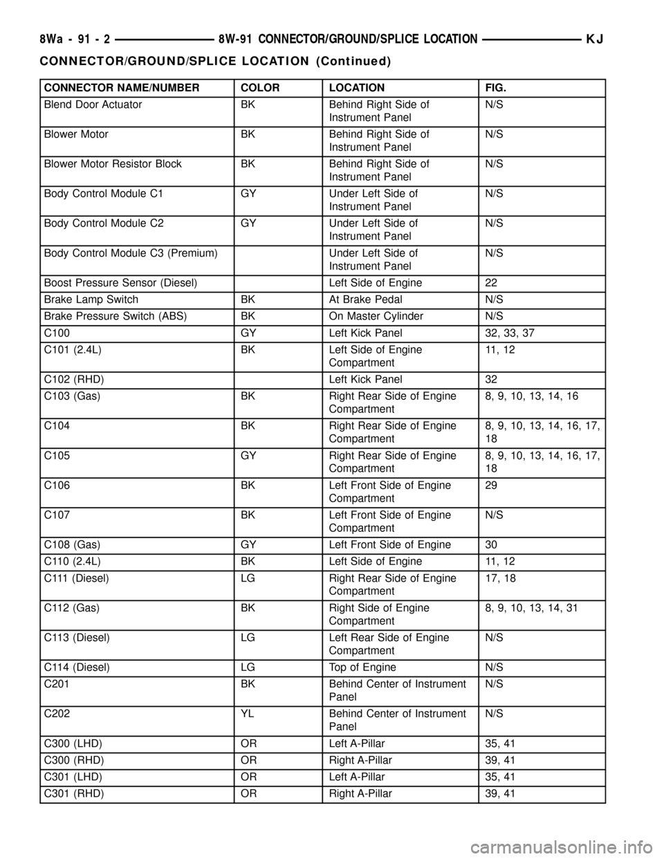
CONNECTOR NAME/NUMBER COLOR LOCATION FIG.
Blend Door Actuator BK Behind Right Side of
Instrument PanelN/S
Blower Motor BK Behind Right Side of
Instrument PanelN/S
Blower Motor Resistor Block BK Behind Right Side of
Instrument PanelN/S
Body Control Module C1 GY Under Left Side of
Instrument PanelN/S
Body Control Module C2 GY Under Left Side of
Instrument PanelN/S
Body Control Module C3 (Premium) Under Left Side of
Instrument PanelN/S
Boost Pressure Sensor (Diesel) Left Side of Engine 22
Brake Lamp Switch BK At Brake Pedal N/S
Brake Pressure Switch (ABS) BK On Master Cylinder N/S
C100 GY Left Kick Panel 32, 33, 37
C101 (2.4L) BK Left Side of Engine
Compartment11 , 1 2
C102 (RHD) Left Kick Panel 32
C103 (Gas) BK Right Rear Side of Engine
Compartment8, 9, 10, 13, 14, 16
C104 BK Right Rear Side of Engine
Compartment8, 9, 10, 13, 14, 16, 17,
18
C105 GY Right Rear Side of Engine
Compartment8, 9, 10, 13, 14, 16, 17,
18
C106 BK Left Front Side of Engine
Compartment29
C107 BK Left Front Side of Engine
CompartmentN/S
C108 (Gas) GY Left Front Side of Engine 30
C110 (2.4L) BK Left Side of Engine 11, 12
C111 (Diesel) LG Right Rear Side of Engine
Compartment17, 18
C112 (Gas) BK Right Side of Engine
Compartment8, 9, 10, 13, 14, 31
C113 (Diesel) LG Left Rear Side of Engine
CompartmentN/S
C114 (Diesel) LG Top of Engine N/S
C201 BK Behind Center of Instrument
PanelN/S
C202 YL Behind Center of Instrument
PanelN/S
C300 (LHD) OR Left A-Pillar 35, 41
C300 (RHD) OR Right A-Pillar 39, 41
C301 (LHD) OR Left A-Pillar 35, 41
C301 (RHD) OR Right A-Pillar 39, 41
8Wa - 91 - 2 8W-91 CONNECTOR/GROUND/SPLICE LOCATIONKJ
CONNECTOR/GROUND/SPLICE LOCATION (Continued)
Page 1159 of 1803
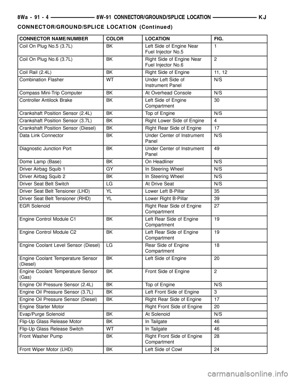
CONNECTOR NAME/NUMBER COLOR LOCATION FIG.
Coil On Plug No.5 (3.7L) BK Left Side of Engine Near
Fuel Injector No.51
Coil On Plug No.6 (3.7L) BK Right Side of Engine Near
Fuel Injector No.62
Coil Rail (2.4L) BK Right Side of Engine 11, 12
Combination Flasher WT Under Left Side of
Instrument PanelN/S
Compass Mini-Trip Computer BK At Overhead Console N/S
Controller Antilock Brake BK Left Side of Engine
Compartment30
Crankshaft Position Sensor (2.4L) BK Top of Engine N/S
Crankshaft Position Sensor (3.7L) BK Right Lower Side of Engine 4
Crankshaft Position Sensor (Diesel) BK Right Rear Side of Engine 17
Data Link Connector BK Under Center of Instrument
PanelN/S
Diagnostic Junction Port BK Under Center of Instrument
Panel49
Dome Lamp (Base) BK On Headliner N/S
Driver Airbag Squib 1 GY In Steering Wheel N/S
Driver Airbag Squib 2 BK In Steering Wheel N/S
Driver Seat Belt Switch LG At Drive Seat N/S
Driver Seat Belt Tensioner (LHD) YL Lower Left B-Pillar 35
Driver Seat Belt Tensioner (RHD) YL Lower Right B-Pillar 39
EGR Solenoid Right Rear Side of Engine
Compartment27
Engine Control Module C1 BK Left Rear Side of Engine
Compartment19
Engine Control Module C2 BK Left Rear Side of Engine
Compartment19
Engine Coolant Level Sensor (Diesel) LG Rear Side of Engine
Compartment18
Engine Coolant Temperature Sensor
(Diesel)BK Left Side of Engine 20
Engine Coolant Temperature Sensor
(Gas)BK Front Side of Engine 2
Engine Oil Pressure Sensor (2.4L) BK Top of Engine N/S
Engine Oil Pressure Sensor (3.7L) BK Left Front Side of Engine 3
Engine Oil Pressure Sensor (Diesel) BK Right Rear Side of Engine 17
Engine Starter Motor Right Front Side of Engine 20
Evap/Purge Solenoid BK At Solenoid N/S
Flip-Up Glass Release Motor BK In Tailgate 46
Flip-Up Glass Release Switch WT In Tailgate 46
Front Washer Pump BK Right Front Side of Engine
Compartment28
Front Wiper Motor (LHD) BK Left Side of Cowl 24
8Wa - 91 - 4 8W-91 CONNECTOR/GROUND/SPLICE LOCATIONKJ
CONNECTOR/GROUND/SPLICE LOCATION (Continued)
Page 1162 of 1803
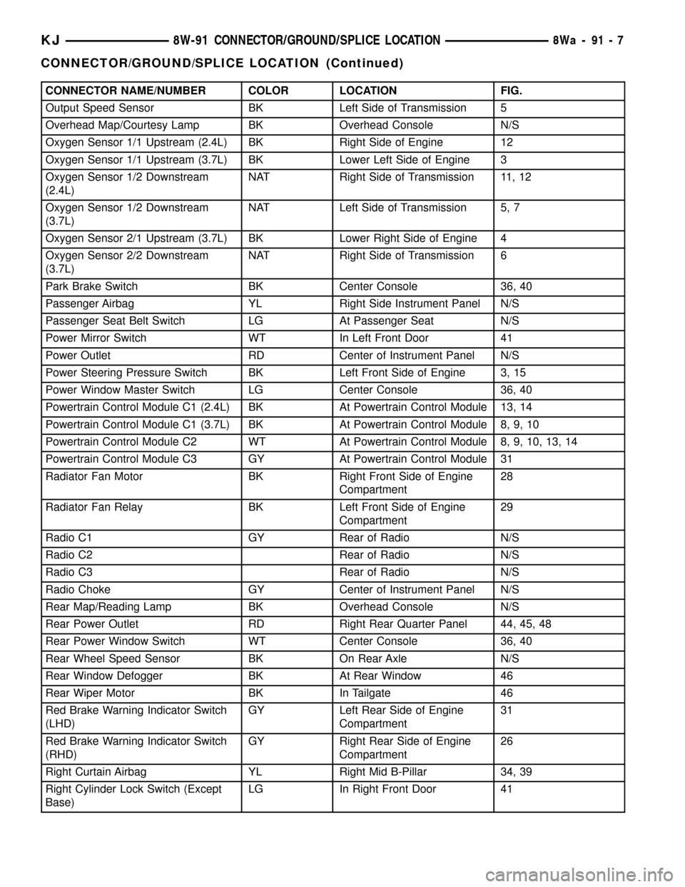
CONNECTOR NAME/NUMBER COLOR LOCATION FIG.
Output Speed Sensor BK Left Side of Transmission 5
Overhead Map/Courtesy Lamp BK Overhead Console N/S
Oxygen Sensor 1/1 Upstream (2.4L) BK Right Side of Engine 12
Oxygen Sensor 1/1 Upstream (3.7L) BK Lower Left Side of Engine 3
Oxygen Sensor 1/2 Downstream
(2.4L)NAT Right Side of Transmission 11, 12
Oxygen Sensor 1/2 Downstream
(3.7L)NAT Left Side of Transmission 5, 7
Oxygen Sensor 2/1 Upstream (3.7L) BK Lower Right Side of Engine 4
Oxygen Sensor 2/2 Downstream
(3.7L)NAT Right Side of Transmission 6
Park Brake Switch BK Center Console 36, 40
Passenger Airbag YL Right Side Instrument Panel N/S
Passenger Seat Belt Switch LG At Passenger Seat N/S
Power Mirror Switch WT In Left Front Door 41
Power Outlet RD Center of Instrument Panel N/S
Power Steering Pressure Switch BK Left Front Side of Engine 3, 15
Power Window Master Switch LG Center Console 36, 40
Powertrain Control Module C1 (2.4L) BK At Powertrain Control Module 13, 14
Powertrain Control Module C1 (3.7L) BK At Powertrain Control Module 8, 9, 10
Powertrain Control Module C2 WT At Powertrain Control Module 8, 9, 10, 13, 14
Powertrain Control Module C3 GY At Powertrain Control Module 31
Radiator Fan Motor BK Right Front Side of Engine
Compartment28
Radiator Fan Relay BK Left Front Side of Engine
Compartment29
Radio C1 GY Rear of Radio N/S
Radio C2 Rear of Radio N/S
Radio C3 Rear of Radio N/S
Radio Choke GY Center of Instrument Panel N/S
Rear Map/Reading Lamp BK Overhead Console N/S
Rear Power Outlet RD Right Rear Quarter Panel 44, 45, 48
Rear Power Window Switch WT Center Console 36, 40
Rear Wheel Speed Sensor BK On Rear Axle N/S
Rear Window Defogger BK At Rear Window 46
Rear Wiper Motor BK In Tailgate 46
Red Brake Warning Indicator Switch
(LHD)GY Left Rear Side of Engine
Compartment31
Red Brake Warning Indicator Switch
(RHD)GY Right Rear Side of Engine
Compartment26
Right Curtain Airbag YL Right Mid B-Pillar 34, 39
Right Cylinder Lock Switch (Except
Base)LG In Right Front Door 41
KJ8W-91 CONNECTOR/GROUND/SPLICE LOCATION8Wa-91-7
CONNECTOR/GROUND/SPLICE LOCATION (Continued)
Page 1164 of 1803
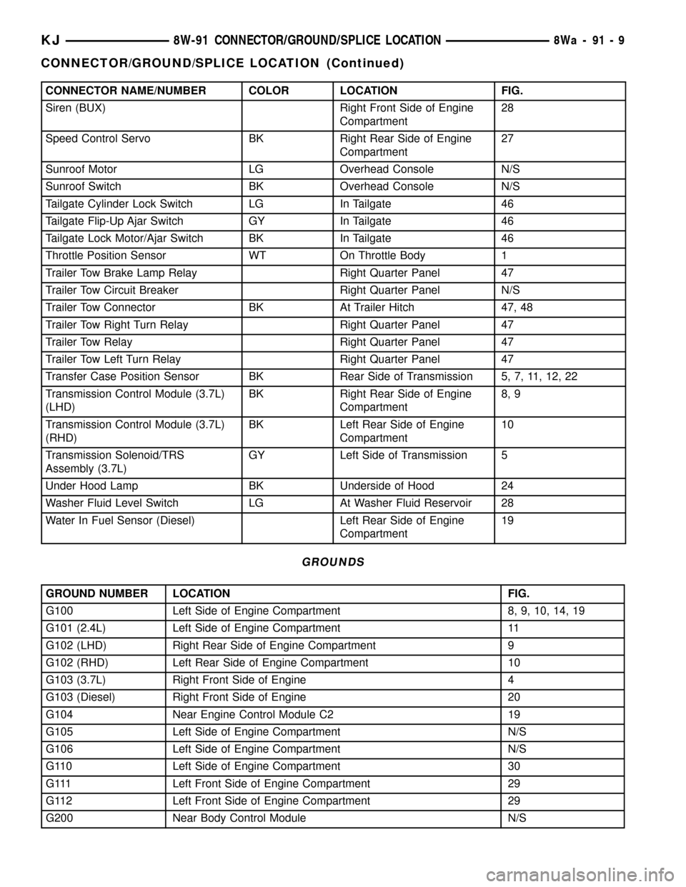
CONNECTOR NAME/NUMBER COLOR LOCATION FIG.
Siren (BUX) Right Front Side of Engine
Compartment28
Speed Control Servo BK Right Rear Side of Engine
Compartment27
Sunroof Motor LG Overhead Console N/S
Sunroof Switch BK Overhead Console N/S
Tailgate Cylinder Lock Switch LG In Tailgate 46
Tailgate Flip-Up Ajar Switch GY In Tailgate 46
Tailgate Lock Motor/Ajar Switch BK In Tailgate 46
Throttle Position Sensor WT On Throttle Body 1
Trailer Tow Brake Lamp Relay Right Quarter Panel 47
Trailer Tow Circuit Breaker Right Quarter Panel N/S
Trailer Tow Connector BK At Trailer Hitch 47, 48
Trailer Tow Right Turn Relay Right Quarter Panel 47
Trailer Tow Relay Right Quarter Panel 47
Trailer Tow Left Turn Relay Right Quarter Panel 47
Transfer Case Position Sensor BK Rear Side of Transmission 5, 7, 11, 12, 22
Transmission Control Module (3.7L)
(LHD)BK Right Rear Side of Engine
Compartment8, 9
Transmission Control Module (3.7L)
(RHD)BK Left Rear Side of Engine
Compartment10
Transmission Solenoid/TRS
Assembly (3.7L)GY Left Side of Transmission 5
Under Hood Lamp BK Underside of Hood 24
Washer Fluid Level Switch LG At Washer Fluid Reservoir 28
Water In Fuel Sensor (Diesel) Left Rear Side of Engine
Compartment19
GROUNDS
GROUND NUMBER LOCATION FIG.
G100 Left Side of Engine Compartment 8, 9, 10, 14, 19
G101 (2.4L) Left Side of Engine Compartment 11
G102 (LHD) Right Rear Side of Engine Compartment 9
G102 (RHD) Left Rear Side of Engine Compartment 10
G103 (3.7L) Right Front Side of Engine 4
G103 (Diesel) Right Front Side of Engine 20
G104 Near Engine Control Module C2 19
G105 Left Side of Engine Compartment N/S
G106 Left Side of Engine Compartment N/S
G110 Left Side of Engine Compartment 30
G111 Left Front Side of Engine Compartment 29
G112 Left Front Side of Engine Compartment 29
G200 Near Body Control Module N/S
KJ8W-91 CONNECTOR/GROUND/SPLICE LOCATION8Wa-91-9
CONNECTOR/GROUND/SPLICE LOCATION (Continued)
Page 1226 of 1803
NOTE: Recheck bolt torque for engine lift plate
before removing engine.
(30) Secure the left and right engine wiring har-
nesses away from engine.
(31) Raise vehicle.
(32) Disconnect oxygen sensor wiring.
(33) Disconnect crankshaft postion sensor.
(34) Disconnect the engine block heater power
cable, if equipped.
(35) Disconnect the front propshaft at the front
differential and secure out of way.
NOTE: It is necessary to disconnect the front prop-
shaft for access to the starter and left side exhaust
flange.
(36) Remove the starter.
(37) Remove the ground straps from the left and
right side of the block.
(38) Disconnect the right and left exhaust pipes at
the manifolds and from the crossover, and remove
from the vehicle.
NOTE: The exhaust clamps at the manifolds cannot
be reused. New clamps must be used or leaks may
occur.
NOTE: For manual transmission vehicles, the trans-
mission must be removed from the vehicle, before
the engine can be removed. The manual transmis-
sion will contact the floorpan before the engine
clears the motor mounts, so it must be removed.
(39) Remove the structural cover.
(40) Remove torque convertor bolts, and mark
location for reassembly.
(41) Remove transmission bellhousing to engine
bolts.
(42) Loosen left and right engine mount thru bolts.
NOTE: It is not necessary to completely remove
engine mount thru bolts, for engine removal.
(43) Lower the vehicle.
(44) Support the transmission with a suitable jack.
(45) Connect a suitable engine hoist to the engine
lift plate.
(46) Remove engine from vehicle.
INSTALLATION
(1) Position the engine in the vehicle.
(2) Install both left and right side engine mounts
onto engine.
(3) Raise the vehicle.(4) Install the transmission bellhousing to engine
mounting bolts. Tighten the bolts to 41 N´m (30ft.
lbs.).
(5) Tighten the engine mount thru bolts.
(6) Install the torque convertor bolts.
(7) Connect the ground straps on the left and right
side of the engine.
(8) Install the starter.
(9) Connect the crankshaft position sensor.
(10) Install the engine block heater power cable, if
equipped.
CAUTION: The structural cover requires a specific
torque sequence. Failure to follow this sequence
may cause severe damage to the cover.
(11) Install the structural cover.
NOTE: New clamps must be used on exhaust man-
ifold flanges. Failure to use new clamps may result
in exhaust leaks.
(12) Install the left and right exhaust pipes.
(13) Connect the left and right oxygen sensors.
(14) Lower vehicle.
(15) Remove the engine lift plate.
(16) Connect the knock sensors.
(17) Connect the engine to body ground straps at
the left side of the cowl.
(18) Install the intake manifold.
(19) Install the engine oil dipstick tube.
(20) Install the power brake booster vacuum hose.
(21) Install the breather hoses.
(22) Install the PCV hose.
(23) Install the fuel rail.
(24) Install the coil over plugs.
(25) Connect the engine wiring harness at the fol-
lowing points:
²Intake air temperature (IAT) sensor
²Fuel Injectors
²Throttle Position (TPS) Switch
²Idle Air Control (IAC) Motor
²Engine Oil Pressure Switch
²Engine Coolant Temperature (ECT) Sensor
²Manifold Absolute Pressure MAP) Sensor
²Camshaft Position (CMP) Sensor
²Coil Over Plugs
²Crankshaft Position Sensor
(26) Connect lower radiator hose.
(27) Connect upper radiator hose.
(28) Connect throttle and speed control cables.
(29) Install the heater hose assembly.
(30) Install coolant recovery bottle.
(31) Install the power steering pump.
(32) Install the generator.
(33) Install the A/C compressor.
(34) Install the drive belt.
KJENGINE - 3.7L 9 - 11
ENGINE - 3.7L (Continued)