2002 JEEP GRAND CHEROKEE moto pil
[x] Cancel search: moto pilPage 360 of 2199

STARTING
TABLE OF CONTENTS
page page
STARTING
DESCRIPTION.........................29
OPERATION...........................30
DIAGNOSIS AND TESTING - STARTING
SYSTEM............................30
SPECIFICATIONS
TORQUE - STARTER...................35
STARTER MOTOR - GAS POWERED......35
STARTER MOTOR
DESCRIPTION.........................35
OPERATION...........................36DIAGNOSIS AND TESTING - STARTER
MOTOR .............................36
REMOVAL.............................37
INSTALLATION.........................38
STARTER MOTOR RELAY
DESCRIPTION.........................38
OPERATION...........................38
DIAGNOSIS AND TESTING - STARTER RELAY . 38
REMOVAL.............................39
INSTALLATION.........................40
STARTING
DESCRIPTION
An electrically operated engine starting system is
standard factory-installed equipment on this model.
The starting system is designed to provide the vehi-
cle operator with a convenient, efficient and reliable
means of cranking and starting the internal combus-
tion engine used to power the vehicle and all of its
accessory systems from within the safe and secure
confines of the passenger compartment. See the own-
er's manual in the vehicle glove box for more infor-
mation and instructions on the recommended use
and operation of the factory-installed starting sys-
tem.
The starting system consists of the following com-
ponents:
²Battery
²Starter relay
²Starter motor (including an integral starter sole-
noid)
²Ignition switch
²Park/neutral position switch
²Wire harnesses and connections (including the
battery cables).
This group provides complete service information
for the starter motor and the starter relay. Complete
service information for the other starting system
components can be located as follows:
²Refer toBatteryin the proper section of Group
8A - Battery for complete service information for the
battery.
²Refer toIgnition Switch and Key Lock Cyl-
inderin the proper section of Group 8D - Ignition
System for complete service information for the igni-
tion switch.²Refer toPark/Neutral Position Switchin the
proper section of Group 21 - Transmission for com-
plete service information for the park/neutral posi-
tion switch.
²Refer to the proper section ofGroup 8W - Wir-
ing Diagramsfor complete service information and
circuit diagrams for the starting system wiring com-
ponents.
Group 8A covers the Battery, Group 8B covers the
Starting Systems, and Group 8C covers the Charging
System. We have separated these systems to make it
easier to locate the information you are seeking
within this Service Manual. However, when attempt-
ing to diagnose any of these systems, it is important
that you keep their interdependency in mind.
The battery, starting, and charging systems in the
vehicle operate with one another, and must be tested
as a complete system. In order for the vehicle to start
and charge properly, all of the components that are
used in these systems must perform within specifica-
tions.
The diagnostic procedures used in each of these
groups include the most basic conventional diagnostic
methods, to the more sophisticated On-Board Diag-
nostics (OBD) built into the Powertrain Control Mod-
ule (PCM). Use of an induction-type milliampere
ammeter, volt/ohmmeter, battery charger, carbon pile
rheostat (load tester), and 12-volt test lamp may be
required.
All OBD-sensed systems are monitored by the
PCM. Each monitored circuit is assigned a Diagnos-
tic Trouble Code (DTC). The PCM will store a DTC in
electronic memory for any failure it detects. Refer to
On-Board Diagnostic Test For Charging System
in the Diagnosis and Testing section of Group 8C -
Charging System for more information.
WJSTARTING 8F - 29
Page 361 of 2199

OPERATION
The starting system components form two separate
circuits. A high-amperage feed circuit that feeds the
starter motor between 150 and 350 amperes, and a
low-amperage control circuit that operates on less
than 20 amperes. The high-amperage feed circuit
components include the battery, the battery cables,
the contact disc portion of the starter solenoid, and
the starter motor. The low-amperage control circuit
components include the ignition switch, the park/
neutral position switch, the starter relay, the electro-
magnetic windings of the starter solenoid, and the
connecting wire harness components.
Battery voltage is supplied through the low-amper-
age control circuit to the coil battery terminal of the
starter relay when the ignition switch is turned to
the momentary Start position. The park/neutral posi-
tion switch is installed in series between the starter
relay coil ground terminal and ground. This normally
open switch prevents the starter relay from being
energized and the starter motor from operating
unless the automatic transmission gear selector is in
the Neutral or Park positions.
When the starter relay coil is energized, the nor-
mally open relay contacts close. The relay contacts
connect the relay common feed terminal to the relay
normally open terminal. The closed relay contacts
energize the starter solenoid coil windings.
The energized solenoid pull-in coil pulls in the sole-
noid plunger. The solenoid plunger pulls the shift
lever in the starter motor. This engages the starter
overrunning clutch and pinion gear with the starter
ring gear on the automatic transmission torque con-
verter drive plate.
As the solenoid plunger reaches the end of its
travel, the solenoid contact disc completes the high-
amperage starter feed circuit and energizes the sole-
noid plunger hold-in coil. Current now flows between
the solenoid battery terminal and the starter motor,
energizing the starter.Once the engine starts, the overrunning clutch pro-
tects the starter motor from damage by allowing the
starter pinion gear to spin faster than the pinion
shaft. When the driver releases the ignition switch to
the On position, the starter relay coil is de-energized.
This causes the relay contacts to open. When the
relay contacts open, the starter solenoid plunger
hold-in coil is de-energized.
When the solenoid plunger hold-in coil is de-ener-
gized, the solenoid plunger return spring returns the
plunger to its relaxed position. This causes the con-
tact disc to open the starter feed circuit, and the shift
lever to disengage the overrunning clutch and pinion
gear from the starter ring gear.
DIAGNOSIS AND TESTING - STARTING
SYSTEM
The battery, starting, and charging systems oper-
ate with one another, and must be tested as a com-
plete system. In order for the vehicle to start and
charge properly, all of the components involved in
these systems must perform within specifications.
Group 8A covers the Battery, Group 8B covers the
Starting Systems, and Group 8C covers the Charging
System. We have separated these systems to make it
easier to locate the information you are seeking
within this Service Manual. However, when attempt-
ing to diagnose any of these systems, it is important
that you keep their interdependency in mind.
The diagnostic procedures used in these groups
include the most basic conventional diagnostic meth-
ods, to the more sophisticated On-Board Diagnostics
(OBD) built into the Powertrain Control Module
(PCM). Use of an induction-type milliampere amme-
ter, volt/ohmmeter, battery charger, carbon pile rheo-
stat (load tester), and 12-volt test lamp may be
required.
All OBD-sensed systems are monitored by the
PCM. Each monitored circuit is assigned a Diagnos-
tic Trouble Code (DTC). The PCM will store a DTC in
electronic memory for any failure it detects. Refer to
On-Board Diagnostic Test For Charging System
in the Diagnosis and Testing section of Group 8C -
Charging System for more information.
8F - 30 STARTINGWJ
STARTING (Continued)
Page 367 of 2199

OPERATION
These starter motors are equipped with a plane-
tary gear reduction (intermediate transmission) sys-
tem. The planetary gear reduction system consists of
a gear that is integral to the output end of the elec-
tric motor armature shaft that is in continual
engagement with a larger gear that is splined to the
input end of the starter pinion gear shaft. This fea-
ture makes it possible to reduce the dimensions of
the starter. At the same time, it allows higher arma-
ture rotational speed and delivers increased torque
through the starter pinion gear to the starter ring
gear.
The starter motors for both engines are activated
by an integral heavy duty starter solenoid switch
mounted to the overrunning clutch housing. This
electromechanical switch connects and disconnects
the feed of battery voltage to the starter motor and
actuates a shift fork that engages and disengages the
starter pinion gear with the starter ring gear.
Both starter motors use an overrunning clutch and
starter pinion gear unit to engage and drive a starter
ring gear that is integral to the torque converter
drive plate mounted on the rear crankshaft flange.
DIAGNOSIS AND TESTING - STARTER MOTOR
Correct starter motor operation can be confirmed
by performing the following free running bench test.
This test can only be performed with the starter
motor removed from the vehicle. Refer toStarting
Systemin the Specifications section of this group for
the starter motor specifications.
(1) Remove the starter motor from the vehicle.
Refer toStarter Motorin the Removal and Instal-
lation section of this group for the procedures.
(2) Mount the starter motor securely in a soft-
jawed bench vise. The vise jaws should be clamped
on the mounting flange of the starter motor. Never
clamp on the starter motor by the field frame.
(3) Connect a suitable volt-ampere tester and a
12-volt battery to the starter motor in series, and set
the ammeter to the 100 ampere scale. See the
instructions provided by the manufacturer of the
volt-ampere tester being used.
(4) Install a jumper wire from the solenoid termi-
nal to the solenoid battery terminal. The starter
motor should operate. If the starter motor fails to
operate, replace the faulty starter motor assembly.
(5) Adjust the carbon pile load of the tester to
obtain the free running test voltage. Refer toStart-
ing Systemin the Specifications section of this
group for the starter motor free running test voltage
specifications.
(6) Note the reading on the ammeter and compare
this reading to the free running test maximum
amperage draw. Refer toStarting Systemin theSpecifications section of this group for the starter
motor free running test maximum amperage draw
specifications.
(7) If the ammeter reading exceeds the maximum
amperage draw specification, replace the faulty
starter motor assembly.
STARTER SOLENOID
This test can only be performed with the starter
motor removed from the vehicle.
(1) Remove the starter motor from the vehicle.
Refer toStarter Motorin the Removal and Instal-
lation section of this group for the procedures.
(2) Disconnect the wire from the solenoid field coil
terminal.
(3) Check for continuity between the solenoid ter-
minal and the solenoid field coil terminal with a con-
tinuity tester (Fig. 7). There should be continuity. If
OK, go to Step 4. If not OK, replace the faulty starter
motor assembly.
(4) Check for continuity between the solenoid ter-
minal and the solenoid case (Fig. 8). There should be
continuity. If not OK, replace the faulty starter motor
assembly.
Fig. 7 Continuity Test Between Solenoid Terminal
and Field Coil Terminal - Typical
1 - SOLENOID
2 - SOLENOID TERMINAL
3 - OHMMETER
4 - FIELD COIL TERMINAL
Fig. 8 Continuity Test Between Solenoid Terminal
1 - SOLENOID
2 - SOLENOID TERMINAL
3 - OHMMETER
8F - 36 STARTINGWJ
STARTER MOTOR (Continued)
Page 645 of 2199
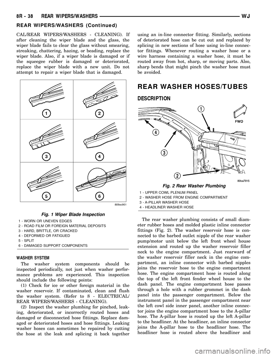
CAL/REAR WIPERS/WASHERS - CLEANING). If
after cleaning the wiper blade and the glass, the
wiper blade fails to clear the glass without smearing,
streaking, chattering, hazing, or beading, replace the
wiper blade. Also, if a wiper blade is damaged or if
the squeegee rubber is damaged or deteriorated,
replace the wiper blade with a new unit. Do not
attempt to repair a wiper blade that is damaged.
WASHER SYSTEM
The washer system components should be
inspected periodically, not just when washer perfor-
mance problems are experienced. This inspection
should include the following points:
(1) Check for ice or other foreign material in the
washer reservoir. If contaminated, clean and flush
the washer system. (Refer to 8 - ELECTRICAL/
REAR WIPERS/WASHERS - CLEANING).
(2) Inspect the washer plumbing for pinched, leak-
ing, deteriorated, or incorrectly routed hoses and
damaged or disconnected hose fittings. Replace dam-
aged or deteriorated hoses and hose fittings. Leaking
washer hoses can sometimes be repaired by cutting
the hose at the leak and splicing it back togetherusing an in-line connector fitting. Similarly, sections
of deteriorated hose can be cut out and replaced by
splicing in new sections of hose using in-line connec-
tor fittings. Whenever routing a washer hose or a
wire harness containing a washer hose, it must be
routed away from hot, sharp, or moving parts. Also,
sharp bends that might pinch the washer hose must
be avoided.
REAR WASHER HOSES/TUBES
DESCRIPTION
The rear washer plumbing consists of small diam-
eter rubber hoses and molded plastic inline connector
fittings (Fig. 2). The washer reservoir hose is con-
nected to the barbed outlet nipple of the rear washer
pump/motor unit below the left front wheel house
extension and routed up the washer reservoir filler
neck to the engine compartment. Just rearward of
the washer reservoir filler neck in the engine com-
partment, an inline connector with barbed nipples
joins the reservoir hose to the engine compartment
hose. The engine compartment hose is routed along
the top of the left front fender wheel house to the
dash panel. The engine compartment hose passes
through a hole with a rubber grommet in the dash
panel into the passenger compartment. Below the
instrument panel in the passenger compartment near
the left cowl side inner panel, another inline connec-
tor joins the engine compartment hose to the A-pillar
hose. The A-pillar hose is routed up the left A-pillar
to the headliner. At the headliner, an inline connector
joins the A-pillar hose to the headliner hose. The
headliner hose is routed above the headliner and
Fig. 1 Wiper Blade Inspection
1 - WORN OR UNEVEN EDGES
2 - ROAD FILM OR FOREIGN MATERIAL DEPOSITS
3 - HARD, BRITTLE, OR CRACKED
4 - DEFORMED OR FATIGUED
5 - SPLIT
6 - DAMAGED SUPPORT COMPONENTS
Fig. 2 Rear Washer Plumbing
1 - UPPER COWL PLENUM PANEL
2 - WASHER HOSE FROM ENGINE COMPARTMENT
3 - A-PILLAR WASHER HOSE
4 - HEADLINER WASHER HOSE
8R - 38 REAR WIPERS/WASHERSWJ
REAR WIPERS/WASHERS (Continued)
Page 1181 of 2199
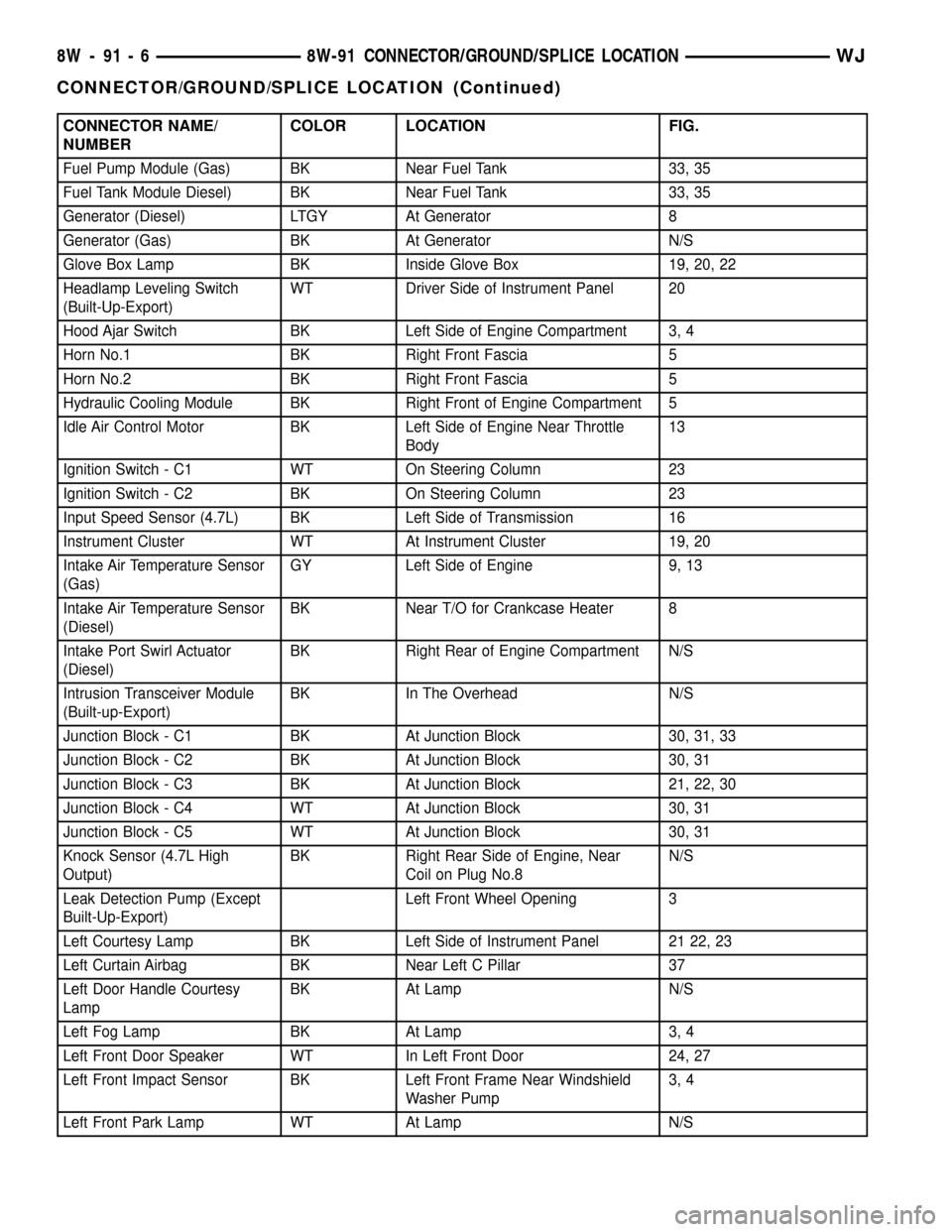
CONNECTOR NAME/
NUMBERCOLOR LOCATION FIG.
Fuel Pump Module (Gas) BK Near Fuel Tank 33, 35
Fuel Tank Module Diesel) BK Near Fuel Tank 33, 35
Generator (Diesel) LTGY At Generator 8
Generator (Gas) BK At Generator N/S
Glove Box Lamp BK Inside Glove Box 19, 20, 22
Headlamp Leveling Switch
(Built-Up-Export)WT Driver Side of Instrument Panel 20
Hood Ajar Switch BK Left Side of Engine Compartment 3, 4
Horn No.1 BK Right Front Fascia 5
Horn No.2 BK Right Front Fascia 5
Hydraulic Cooling Module BK Right Front of Engine Compartment 5
Idle Air Control Motor BK Left Side of Engine Near Throttle
Body13
Ignition Switch - C1 WT On Steering Column 23
Ignition Switch - C2 BK On Steering Column 23
Input Speed Sensor (4.7L) BK Left Side of Transmission 16
Instrument Cluster WT At Instrument Cluster 19, 20
Intake Air Temperature Sensor
(Gas)GY Left Side of Engine 9, 13
Intake Air Temperature Sensor
(Diesel)BK Near T/O for Crankcase Heater 8
Intake Port Swirl Actuator
(Diesel)BK Right Rear of Engine Compartment N/S
Intrusion Transceiver Module
(Built-up-Export)BK In The Overhead N/S
Junction Block - C1 BK At Junction Block 30, 31, 33
Junction Block - C2 BK At Junction Block 30, 31
Junction Block - C3 BK At Junction Block 21, 22, 30
Junction Block - C4 WT At Junction Block 30, 31
Junction Block - C5 WT At Junction Block 30, 31
Knock Sensor (4.7L High
Output)BK Right Rear Side of Engine, Near
Coil on Plug No.8N/S
Leak Detection Pump (Except
Built-Up-Export)Left Front Wheel Opening 3
Left Courtesy Lamp BK Left Side of Instrument Panel 21 22, 23
Left Curtain Airbag BK Near Left C Pillar 37
Left Door Handle Courtesy
LampBK At Lamp N/S
Left Fog Lamp BK At Lamp 3, 4
Left Front Door Speaker WT In Left Front Door 24, 27
Left Front Impact Sensor BK Left Front Frame Near Windshield
Washer Pump3, 4
Left Front Park Lamp WT At Lamp N/S
8W - 91 - 6 8W-91 CONNECTOR/GROUND/SPLICE LOCATIONWJ
CONNECTOR/GROUND/SPLICE LOCATION (Continued)
Page 1184 of 2199
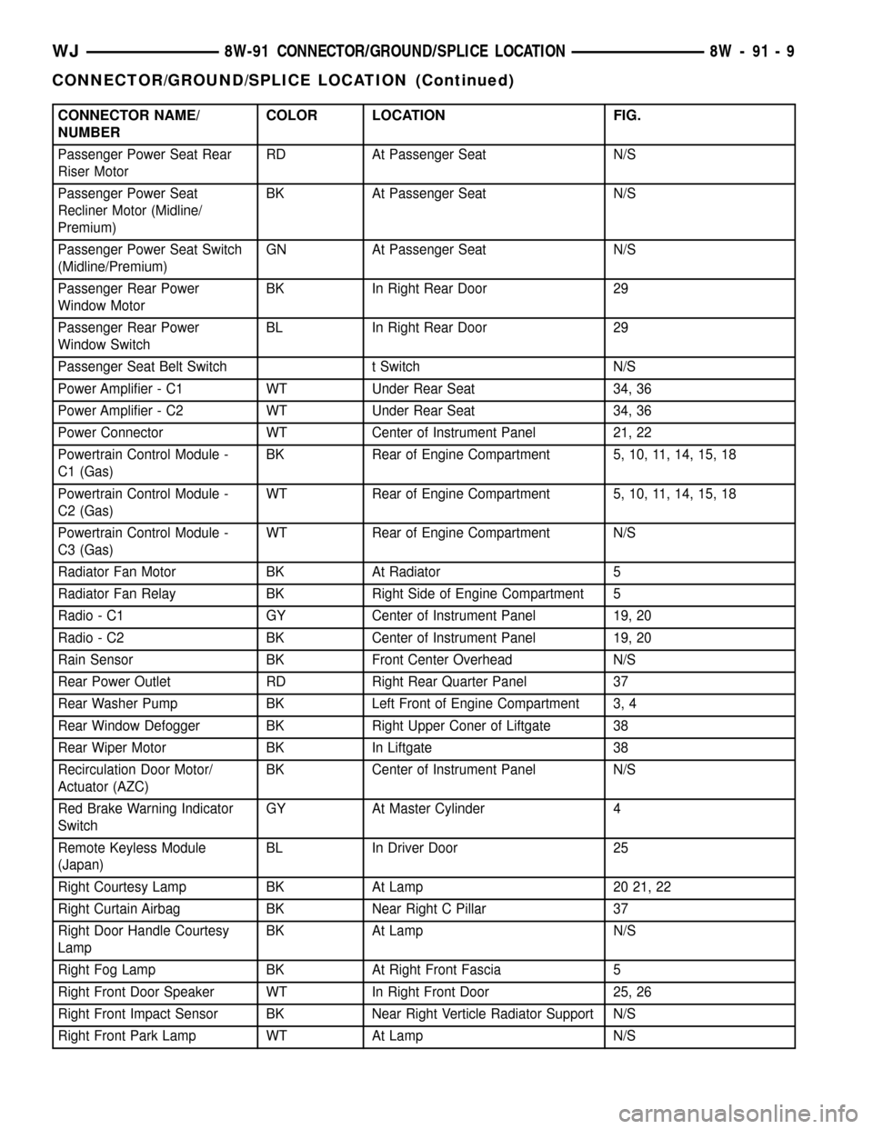
CONNECTOR NAME/
NUMBERCOLOR LOCATION FIG.
Passenger Power Seat Rear
Riser MotorRD At Passenger Seat N/S
Passenger Power Seat
Recliner Motor (Midline/
Premium)BK At Passenger Seat N/S
Passenger Power Seat Switch
(Midline/Premium)GN At Passenger Seat N/S
Passenger Rear Power
Window MotorBK In Right Rear Door 29
Passenger Rear Power
Window SwitchBL In Right Rear Door 29
Passenger Seat Belt Switch t Switch N/S
Power Amplifier - C1 WT Under Rear Seat 34, 36
Power Amplifier - C2 WT Under Rear Seat 34, 36
Power Connector WT Center of Instrument Panel 21, 22
Powertrain Control Module -
C1 (Gas)BK Rear of Engine Compartment 5, 10, 11, 14, 15, 18
Powertrain Control Module -
C2 (Gas)WT Rear of Engine Compartment 5, 10, 11, 14, 15, 18
Powertrain Control Module -
C3 (Gas)WT Rear of Engine Compartment N/S
Radiator Fan Motor BK At Radiator 5
Radiator Fan Relay BK Right Side of Engine Compartment 5
Radio - C1 GY Center of Instrument Panel 19, 20
Radio - C2 BK Center of Instrument Panel 19, 20
Rain Sensor BK Front Center Overhead N/S
Rear Power Outlet RD Right Rear Quarter Panel 37
Rear Washer Pump BK Left Front of Engine Compartment 3, 4
Rear Window Defogger BK Right Upper Coner of Liftgate 38
Rear Wiper Motor BK In Liftgate 38
Recirculation Door Motor/
Actuator (AZC)BK Center of Instrument Panel N/S
Red Brake Warning Indicator
SwitchGY At Master Cylinder 4
Remote Keyless Module
(Japan)BL In Driver Door 25
Right Courtesy Lamp BK At Lamp 20 21, 22
Right Curtain Airbag BK Near Right C Pillar 37
Right Door Handle Courtesy
LampBK At Lamp N/S
Right Fog Lamp BK At Right Front Fascia 5
Right Front Door Speaker WT In Right Front Door 25, 26
Right Front Impact Sensor BK Near Right Verticle Radiator Support N/S
Right Front Park Lamp WT At Lamp N/S
WJ8W-91 CONNECTOR/GROUND/SPLICE LOCATION 8W - 91 - 9
CONNECTOR/GROUND/SPLICE LOCATION (Continued)
Page 1191 of 2199
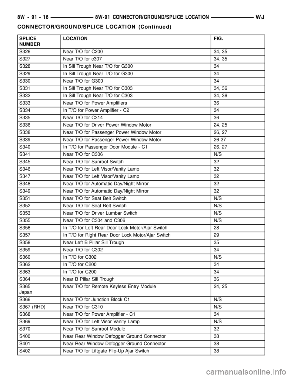
SPLICE
NUMBERLOCATION FIG.
S326 Near T/O for C200 34, 35
S327 Near T/O for c307 34, 35
S328 In Sill Trough Near T/O for G300 34
S329 In Sill Trough Near T/O for G300 34
S330 Near T/O for G300 34
S331 In Sill Trough Near T/O for C303 34, 36
S332 In Sill Trough Near T/O for C303 34, 36
S333 Near T/O for Power Amplifiers 36
S334 In T/O for Power Amplifier - C2 34
S335 Near T/O for C314 36
S336 Near T/O for Driver Power Window Motor 24, 25
S338 Near T/O for Passenger Power Window Motor 26, 27
S339 Near T/O for Passenger Power Window Motor 26 27
S340 In T/O for Passenger Door Module - C1 26, 27
S341 Near T/O for C306 N/S
S345 Near T/O for Sunroof Switch 32
S346 Near T/O for Left Visor/Vanity Lamp 32
S347 Near T/O for Left Visor/Vanity Lamp 32
S348 Near T/O for Automatic Day/Night Mirror 32
S349 Near T/O for Automatic Day/Night Mirror 32
S351 Near T/O for Seat Belt Switch N/S
S352 Near T/O for Seat Belt Switch N/S
S353 Near T/O for Driver Lumbar Switch N/S
S355 Near T/O for C304 and C306 N/S
S356 In T/O for Left Rear Door Lock Motor/Ajar Switch 28
S357 In T/O for Right Rear Door Lock Motor/Ajar Switch 29
S358 Near Left B Pillar Sill Trough 35
S359 Near T/O for C302 34
S360 In T/O for C302 N/S
S362 In T/O for C200 34
S363 In T/O for C200 34
S364 Near B Pillar Sill Trough 36
S365
JapanNear T/O for Remote Keyless Entry Module 24, 25
S366 Near T/O for Junction Block C1 N/S
S367 (RHD) Near T/O for C310 N/S
S368 Near T/O for Power Amplifier - C1 34
S369 Near T/O for Left Visor Vanity Lamp N/S
S370 Near T/O for Sunroof Module 32
S400 Near Rear Window Defogger Ground Connector 38
S401 Near Rear Window Defogger Ground Connector 38
S402 Near T/O for Liftgate Flip-Up Ajar Switch 38
8W - 91 - 16 8W-91 CONNECTOR/GROUND/SPLICE LOCATIONWJ
CONNECTOR/GROUND/SPLICE LOCATION (Continued)
Page 1297 of 2199
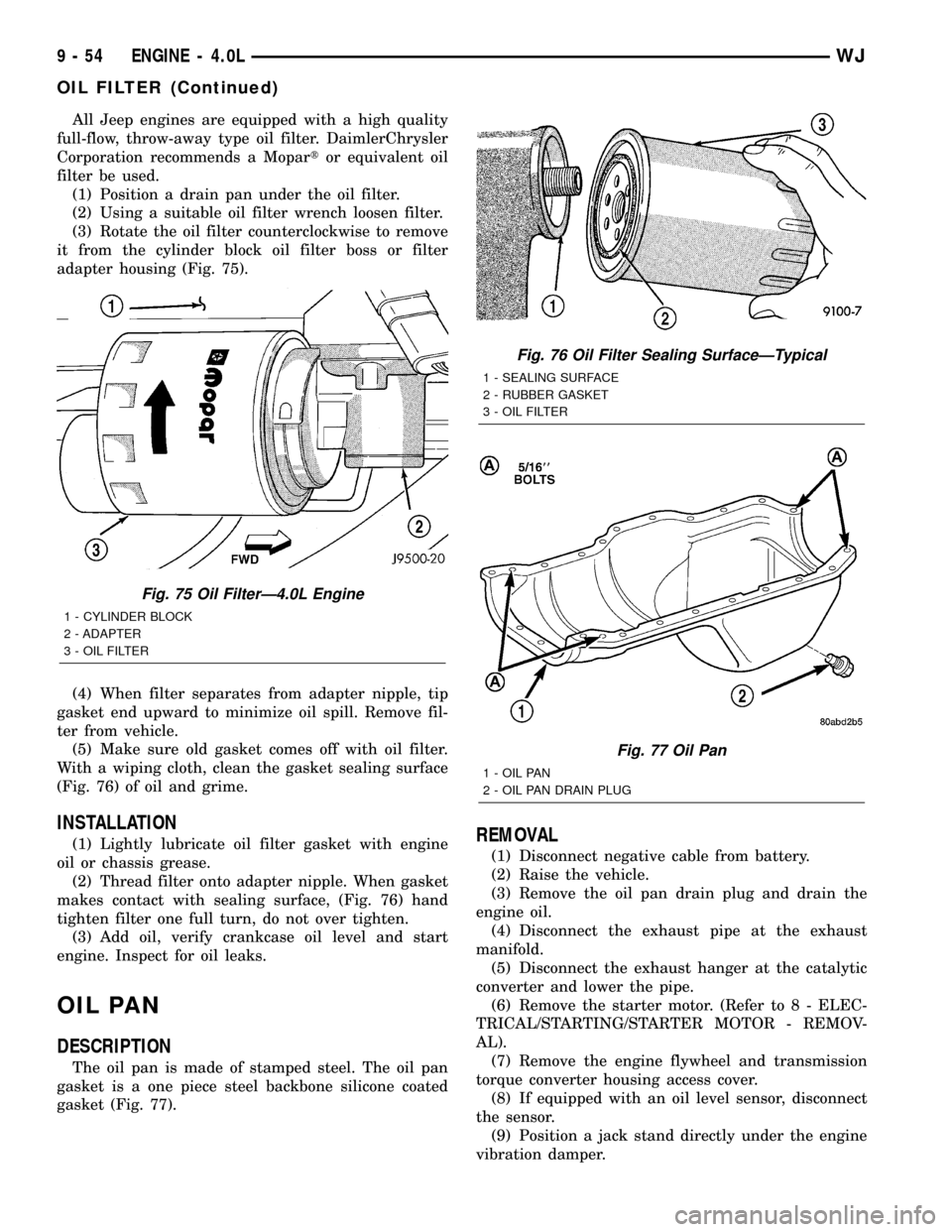
All Jeep engines are equipped with a high quality
full-flow, throw-away type oil filter. DaimlerChrysler
Corporation recommends a Mopartor equivalent oil
filter be used.
(1) Position a drain pan under the oil filter.
(2) Using a suitable oil filter wrench loosen filter.
(3) Rotate the oil filter counterclockwise to remove
it from the cylinder block oil filter boss or filter
adapter housing (Fig. 75).
(4) When filter separates from adapter nipple, tip
gasket end upward to minimize oil spill. Remove fil-
ter from vehicle.
(5) Make sure old gasket comes off with oil filter.
With a wiping cloth, clean the gasket sealing surface
(Fig. 76) of oil and grime.
INSTALLATION
(1) Lightly lubricate oil filter gasket with engine
oil or chassis grease.
(2) Thread filter onto adapter nipple. When gasket
makes contact with sealing surface, (Fig. 76) hand
tighten filter one full turn, do not over tighten.
(3) Add oil, verify crankcase oil level and start
engine. Inspect for oil leaks.
OIL PAN
DESCRIPTION
The oil pan is made of stamped steel. The oil pan
gasket is a one piece steel backbone silicone coated
gasket (Fig. 77).
REMOVAL
(1) Disconnect negative cable from battery.
(2) Raise the vehicle.
(3) Remove the oil pan drain plug and drain the
engine oil.
(4) Disconnect the exhaust pipe at the exhaust
manifold.
(5) Disconnect the exhaust hanger at the catalytic
converter and lower the pipe.
(6) Remove the starter motor. (Refer to 8 - ELEC-
TRICAL/STARTING/STARTER MOTOR - REMOV-
AL).
(7) Remove the engine flywheel and transmission
torque converter housing access cover.
(8) If equipped with an oil level sensor, disconnect
the sensor.
(9) Position a jack stand directly under the engine
vibration damper.
Fig. 75 Oil FilterÐ4.0L Engine
1 - CYLINDER BLOCK
2 - ADAPTER
3 - OIL FILTER
Fig. 76 Oil Filter Sealing SurfaceÐTypical
1 - SEALING SURFACE
2 - RUBBER GASKET
3 - OIL FILTER
Fig. 77 Oil Pan
1 - OIL PAN
2 - OIL PAN DRAIN PLUG
9 - 54 ENGINE - 4.0LWJ
OIL FILTER (Continued)