2002 JEEP GRAND CHEROKEE Transfer
[x] Cancel search: TransferPage 1506 of 2199

INSTALLATION
(1) Install the steering damper to the axle bracket
and tie rod.
(2) Install the steering damper bolt in the axle
bracket and tighten bolt to 88 N´m (65 ft. lbs.).
(3) Install the nut at the tie rod and tighten to 41
N´m (30 ft. lbs.).
DRAG LINK
DESCRIPTION
The drag link and ends are comprised of two forged
ends connected by a steel adjusting tube. The drag
link connects the steering gear pitman arm to the
steering knuckle. The larger offset end is attached to
the pitman arm.
OPERATION
The sleeve is used for steering wheel centering.
REMOVAL
(1) Raise and support the vehicle.
(2) Remove right wheel and tire assembly.
(3) Remove the cotter pins and nuts at the right
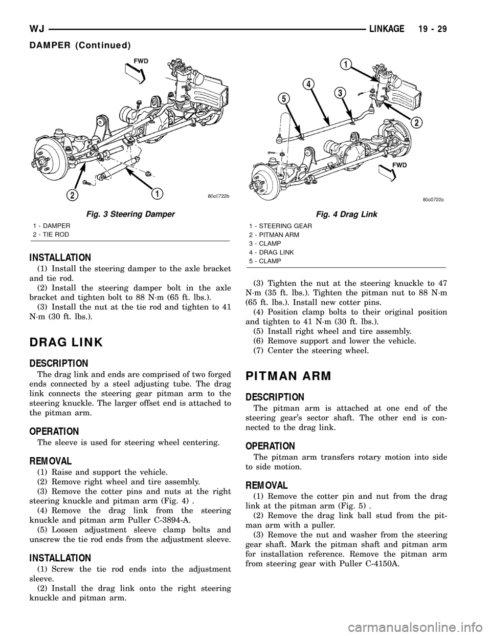
steering knuckle and pitman arm (Fig. 4) .
(4) Remove the drag link from the steering
knuckle and pitman arm Puller C-3894-A.
(5) Loosen adjustment sleeve clamp bolts and
unscrew the tie rod ends from the adjustment sleeve.
INSTALLATION
(1) Screw the tie rod ends into the adjustment
sleeve.
(2) Install the drag link onto the right steering
knuckle and pitman arm.(3) Tighten the nut at the steering knuckle to 47
N´m (35 ft. lbs.). Tighten the pitman nut to 88 N´m
(65 ft. lbs.). Install new cotter pins.
(4) Position clamp bolts to their original position
and tighten to 41 N´m (30 ft. lbs.).
(5) Install right wheel and tire assembly.
(6) Remove support and lower the vehicle.
(7) Center the steering wheel.
PITMAN ARM
DESCRIPTION
The pitman arm is attached at one end of the
steering gear's sector shaft. The other end is con-
nected to the drag link.
OPERATION
The pitman arm transfers rotary motion into side
to side motion.
REMOVAL
(1) Remove the cotter pin and nut from the drag
link at the pitman arm (Fig. 5) .
(2) Remove the drag link ball stud from the pit-
man arm with a puller.
(3) Remove the nut and washer from the steering
gear shaft. Mark the pitman shaft and pitman arm
for installation reference. Remove the pitman arm
from steering gear with Puller C-4150A.
Fig. 3 Steering Damper
1 - DAMPER
2 - TIE ROD
Fig. 4 Drag Link
1 - STEERING GEAR
2 - PITMAN ARM
3 - CLAMP
4 - DRAG LINK
5 - CLAMP
WJLINKAGE 19 - 29
DAMPER (Continued)
Page 1507 of 2199

INSTALLATION
(1) Align and install the pitman arm on steering
gear shaft.
(2) Install the washer and nut on the shaft and
tighten the nut to 251 N´m (185 ft. lbs.).
(3) Install drag link ball stud to pitman arm.
Install nut and tighten to 88 N´m (65 ft. lbs.). Install
a new cotter pin.
TIE ROD END
DESCRIPTION
The ends are forged, with a lubed for life ball
socket.
OPERATION
The tie rod ends connect the drag link to the wheel
assembly. The tie rod provides toe alignment and
transfers steering input from the drag link to the
wheels.
REMOVAL
(1) Raise and support the vehicle.
(2) Remove wheel and tire assemblies.
(3) Remove the damper nut from the tie rod clamp
(Fig. 6).
(4) Remove the damper from the tie rod.
(5) Remove the cotter pins and nuts from the tie
rod ends at the steering knuckles (Fig. 6).(6) Remove the tie rod ends from the steering
knuckles with Puller C-3894-A..
(7) Loosen the adjustment sleeve clamp bolts and
unscrew the tie rod ends from the sleeve.
INSTALLATION
(1) Screw the tie rod ends into the adjustment
sleeve.
(2) Install the tie rod on the steering knuckles and
install the nuts.
(3) Tighten the nuts to 47 N´m (35 ft. lbs.). Install
new cotter pins and bend end 60É.
(4) Position the adjustment sleeve clamp bolts to
their original location and tighten to 41 N´m (30 ft.
lbs.).
(5) Install the damper on the tie rod and install
the nut.
(6) Tighten the nut to 41 N´m (30 ft. lbs.). Install
new cotter pins and bend end 60É.
(7) Install wheel and tire assemblies.
(8) Remove support and lower the vehicle.
(9) Perform toe position adjustment.
Fig. 5 Pitman Arm
1 - STEERING GEAR
2 - PITMAN ARM
Fig. 6 Tie Rod Assembly
1 - TIE ROD END
2 - CLAMP
3 - DAMPER
4 - TIE ROD
5 - CLAMP
6 - TIE ROD END
19 - 30 LINKAGEWJ
PITMAN ARM (Continued)
Page 1514 of 2199

INSTALLATION
(1) Position and install the power steering cooler
to the vehicle.
(2) Install the three mounting bracket bolts (Fig.
6).
(3) Reconnect the upper hose at cooler (Fig. 6).
(4) Reconnect the lower hose at cooler (Fig. 6).
(5) Connect negative battery cable to battery.
(6) Refill the power steering fluid and bleed the
system,(Refer to 19 - STEERING/PUMP - STAN-
DARD PROCEDURE).
(7) Start engine and check for leaks.
(8) Install the grille opening reinforcement panel
(9) Install the front fascia grille,(Refer to 13 -
FRAMES & BUMPERS/BUMPERS/FRONT FASCIA
- INSTALLATION).
HOSES - 4.0L
DESCRIPTION
DESCRIPTION - PRESSURE LINE
The hose consists of two metal ends and rubber
center section that contains a tuning cable. The
pump end uses a quick connect fitting. Lubircation
must be used on the quick connect nut and o-ring
when installing.
DESCRIPTION - RETURN LINE
Power steering return line is a hose which is
clamped at the pump and the gear.
OPERATION
OPERATION - PRESSURE LINE
Power steering pressure line, is used to transfer
high pressure power steering fluid, from the power
steering pump to the power steering gear on the
4.0L. The 4.7L power steering pressure line, is used
to transfer high pressure power steering fluid, from
the power steering pump to the engine cooling fan
and the steering gear.
OPERATION - RETURN LINE
Power steering return line, is used to transfer low
pressure power steering fluid, from the power steer-
ing gear to the power steering pump.
REMOVAL
(1) Drain the power steering fluid from the reser-
voir.
(2) Remove the air box,(Refer to 9 - ENGINE/AIR
INTAKE SYSTEM/AIR CLEANER HOUSING -
REMOVAL).
(3) Disconnect the power steering pressure hose
from the power steering pump and then the power
steering gear (Fig. 7).
(4) Disconnect the power steering return hose from
the power steering cooler and the reservoir.
(5) Remove the hoses from the vehicle.
INSTALLATION
(1) Install the hoses to the vehicle.
(2) Reconnect the power steering return hose to
the power steering cooler and the reservoir.
(3) Reconnect the power steering pressure hose to
the power steering pump and then the power steer-
ing gear.
(4) Install the air box,(Refer to 9 - ENGINE/AIR
INTAKE SYSTEM/AIR CLEANER HOUSING -
INSTALLATION).
(5) Refill the power steering fluid and bleed the
system,(Refer to 19 - STEERING/PUMP - STAN-
DARD PROCEDURE).
Fig. 7 POWER STEERING HOSES
1 - RETURN HOSE
2 - HIGH PRESSURE HOSE
3 - STEERING GEAR
WJPUMP 19 - 37
FLUID COOLER (Continued)
Page 1515 of 2199

HOSES - 4.7L
DESCRIPTION
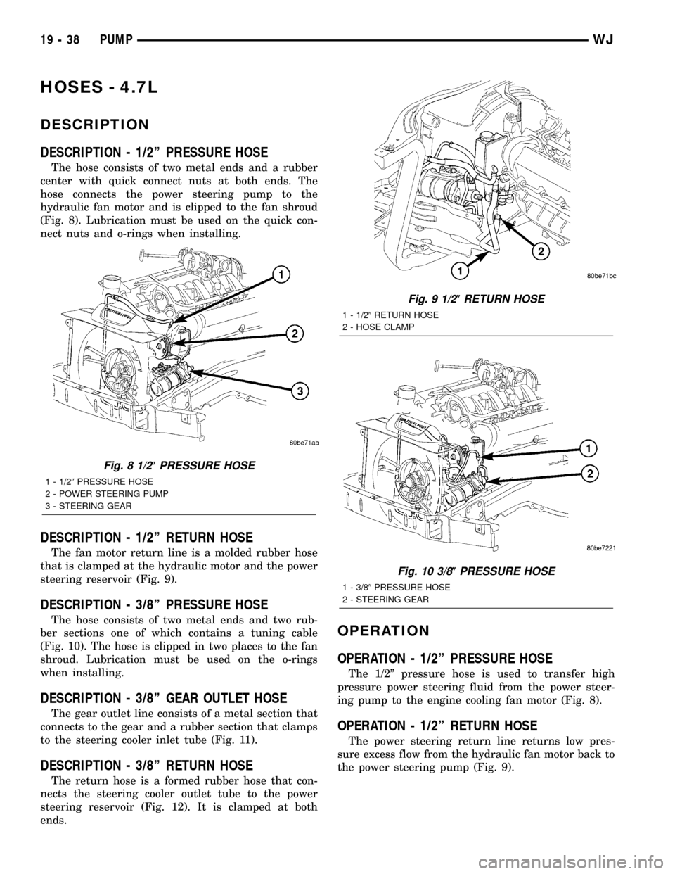
DESCRIPTION - 1/2º PRESSURE HOSE
The hose consists of two metal ends and a rubber
center with quick connect nuts at both ends. The
hose connects the power steering pump to the
hydraulic fan motor and is clipped to the fan shroud
(Fig. 8). Lubrication must be used on the quick con-
nect nuts and o-rings when installing.
DESCRIPTION - 1/2º RETURN HOSE
The fan motor return line is a molded rubber hose
that is clamped at the hydraulic motor and the power
steering reservoir (Fig. 9).
DESCRIPTION - 3/8º PRESSURE HOSE
The hose consists of two metal ends and two rub-
ber sections one of which contains a tuning cable
(Fig. 10). The hose is clipped in two places to the fan
shroud. Lubrication must be used on the o-rings
when installing.
DESCRIPTION - 3/8º GEAR OUTLET HOSE
The gear outlet line consists of a metal section that
connects to the gear and a rubber section that clamps
to the steering cooler inlet tube (Fig. 11).
DESCRIPTION - 3/8º RETURN HOSE
The return hose is a formed rubber hose that con-
nects the steering cooler outlet tube to the power
steering reservoir (Fig. 12). It is clamped at both
ends.
OPERATION
OPERATION - 1/2º PRESSURE HOSE
The 1/2º pressure hose is used to transfer high
pressure power steering fluid from the power steer-
ing pump to the engine cooling fan motor (Fig. 8).
OPERATION - 1/2º RETURN HOSE
The power steering return line returns low pres-
sure excess flow from the hydraulic fan motor back to
the power steering pump (Fig. 9).
Fig. 8 1/2(PRESSURE HOSE
1 - 1/29PRESSURE HOSE
2 - POWER STEERING PUMP
3 - STEERING GEAR
Fig. 9 1/2(RETURN HOSE
1 - 1/29RETURN HOSE
2 - HOSE CLAMP
Fig. 10 3/8(PRESSURE HOSE
1 - 3/89PRESSURE HOSE
2 - STEERING GEAR
19 - 38 PUMPWJ
Page 1520 of 2199

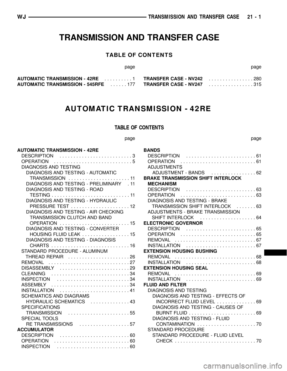
TRANSMISSION AND TRANSFER CASE
TABLE OF CONTENTS
page page
AUTOMATIC TRANSMISSION - 42RE..........1
AUTOMATIC TRANSMISSION - 545RFE......177TRANSFER CASE - NV242................280
TRANSFER CASE - NV247................315
AUTOMATIC TRANSMISSION - 42RE
TABLE OF CONTENTS
page page
AUTOMATIC TRANSMISSION - 42RE
DESCRIPTION..........................3
OPERATION............................5
DIAGNOSIS AND TESTING
DIAGNOSIS AND TESTING - AUTOMATIC
TRANSMISSION......................11
DIAGNOSIS AND TESTING - PRELIMINARY . 11
DIAGNOSIS AND TESTING - ROAD
TESTING............................11
DIAGNOSIS AND TESTING - HYDRAULIC
PRESSURE TEST.....................12
DIAGNOSIS AND TESTING - AIR CHECKING
TRANSMISSION CLUTCH AND BAND
OPERATION.........................15
DIAGNOSIS AND TESTING - CONVERTER
HOUSING FLUID LEAK.................15
DIAGNOSIS AND TESTING - DIAGNOSIS
CHARTS............................16
STANDARD PROCEDURE - ALUMINUM
THREAD REPAIR......................26
REMOVAL.............................27
DISASSEMBLY.........................29
CLEANING............................34
INSPECTION..........................34
ASSEMBLY............................34
INSTALLATION.........................41
SCHEMATICS AND DIAGRAMS
HYDRAULIC SCHEMATICS..............43
SPECIFICATIONS
TRANSMISSION......................55
SPECIAL TOOLS
RE TRANSMISSIONS..................57
ACCUMULATOR
DESCRIPTION.........................60
OPERATION...........................60
INSPECTION..........................60BANDS
DESCRIPTION.........................61
OPERATION...........................61
ADJUSTMENTS
ADJUSTMENT - BANDS................62
BRAKE TRANSMISSION SHIFT INTERLOCK
MECHANISM
DESCRIPTION.........................63
OPERATION...........................63
DIAGNOSIS AND TESTING - BRAKE
TRANSMISSION SHIFT INTERLOCK.......63
ADJUSTMENTS - BRAKE TRANSMISSION
SHIFT INTERLOCK....................64
ELECTRONIC GOVERNOR
DESCRIPTION.........................65
OPERATION...........................65
REMOVAL.............................67
INSTALLATION.........................67
EXTENSION HOUSING BUSHING
REMOVAL.............................68
INSTALLATION.........................68
EXTENSION HOUSING SEAL
REMOVAL.............................69
INSTALLATION.........................69
FLUID AND FILTER
DIAGNOSIS AND TESTING
DIAGNOSIS AND TESTING - EFFECTS OF
INCORRECT FLUID LEVEL..............69
DIAGNOSIS AND TESTING - CAUSES OF
BURNT FLUID........................69
DIAGNOSIS AND TESTING - FLUID
CONTAMINATION.....................70
STANDARD PROCEDURE
STANDARD PROCEDURE - FLUID LEVEL
CHECK.............................70
WJTRANSMISSION AND TRANSFER CASE 21 - 1
Page 1522 of 2199

STANDARD PROCEDURE - TORQUE
CONVERTER DRAINBACK VALVE........134
TRANSMISSION TEMPERATURE SENSOR
DESCRIPTION........................134
OPERATION..........................134
VALVE BODY
DESCRIPTION........................135
OPERATION..........................139REMOVAL............................154
DISASSEMBLY........................155
CLEANING...........................165
INSPECTION.........................166
ASSEMBLY...........................167
INSTALLATION........................175
ADJUSTMENTS - VALVE BODY...........175
AUTOMATIC TRANSMISSION -
42RE
DESCRIPTION
The 42RE is a four speed fully automatic transmis-
sion (Fig. 1) with an electronic governor. The 42RE is
equipped with a lock-up clutch in the torque con-
verter. First through third gear ranges are provided
by the clutches, bands, overrunning clutch, and plan-
etary gear sets in the transmission. Fourth gear
range is provided by the overdrive unit that contains
an overdrive clutch, direct clutch, planetary gear set,
and overrunning clutch.The transmission contains a front, rear, and direct
clutch which function as the input driving compo-
nents. It also contains the kickdown (front) and the
low/reverse (rear) bands which, along with the over-
running clutch and overdrive clutch, serve as the
holding components. The driving and holding compo-
nents combine to select the necessary planetary gear
components, in the front, rear, or overdrive planetary
gear set, transfer the engine power from the input
shaft through to the output shaft.
The valve body is mounted to the lower side of the
transmission and contains the valves to control pres-
sure regulation, fluid flow control, and clutch/band
application. The oil pump is mounted at the front of
the transmission and is driven by the torque con-
verter hub. The pump supplies the oil pressure nec-
essary for clutch/band actuation and transmission
lubrication.
WJAUTOMATIC TRANSMISSION - 42RE 21 - 3
Page 1526 of 2199

REVERSE POWERFLOW
When the gear selector is moved into the
REVERSE position (Fig. 5), the front clutch and the
rear band are applied. With the application of the
front clutch, engine torque is applied to the sun gear,
turning it in a clockwise direction. The clockwise
rotation of the sun gear causes the rear planet pin-
ions to rotate against engine rotation in a counter-
clockwise direction. The rear band is holding the low
reverse drum, which is splined to the rear carrier.
Since the rear carrier is being held, the torque fromthe planet pinions is transferred to the rear annulus
gear, which is splined to the output shaft. The output
shaft in turn rotates with the annulus gear in a
counterclockwise direction giving a reverse gear out-
put. The entire transmission of torque is applied to
the rear planetary gearset only. Although there is
torque input to the front gearset through the sun
gear, no other member of the gearset is being held.
During the entire reverse stage of operation, the
front planetary gears are in an idling condition.
Fig. 5 Reverse Powerflow
1 - FRONT CLUTCH ENGAGED 5 - OUTPUT SHAFT
2 - OUTPUT SHAFT 6 - INPUT SHAFT
3 - LOW/REVERSE BAND APPLIED 7 - FRONT CLUTCH ENGAGED
4 - INPUT SHAFT 8 - LOW/REVERSE BAND APPLIED
WJAUTOMATIC TRANSMISSION - 42RE 21 - 7
AUTOMATIC TRANSMISSION - 42RE (Continued)
Page 1527 of 2199

FIRST GEAR POWERFLOW
When the gearshift lever is moved into the DRIVE
position the transmission goes into first gear (Fig. 6).
As soon as the transmission is shifted from PARK or
NEUTRAL to DRIVE, the rear clutch applies, apply-
ing the rear clutch pack to the front annulus gear.
Engine torque is now applied to the front annulus
gear turning it in a clockwise direction. With the
front annulus gear turning in a clockwise direction, it
causes the front planets to turn in a clockwise direc-
tion. The rotation of the front planets cause the sun
to revolve in a counterclockwise direction. The sun
gear now transfers its counterclockwise rotation tothe rear planets which rotate back in a clockwise
direction. With the rear annulus gear stationary, the
rear planet rotation on the annulus gear causes the
rear planet carrier to revolve in a counterclockwise
direction. The rear planet carrier is splined into the
low-reverse drum, and the low reverse drum is
splined to the inner race of the over-running clutch.
With the over-running clutch locked, the planet car-
rier is held, and the resulting torque provided by the
planet pinions is transferred to the rear annulus
gear. The rear annulus gear is splined to the output
shaft and rotated along with it (clockwise) in an
underdrive gear reduction mode.
Fig. 6 First Gear Powerflow
1 - OUTPUT SHAFT 5 - OVER-RUNNING CLUTCH HOLDING
2 - OVER-RUNNING CLUTCH HOLDING 6 - INPUT SHAFT
3 - REAR CLUTCH APPLIED 7 - REAR CLUTCH APPLIED
4 - OUTPUT SHAFT 8 - INPUT SHAFT
21 - 8 AUTOMATIC TRANSMISSION - 42REWJ
AUTOMATIC TRANSMISSION - 42RE (Continued)