2002 JEEP GRAND CHEROKEE Lighting
[x] Cancel search: LightingPage 912 of 2199

8W-44 INTERIOR LIGHTING
Component Page
Ash Receiver Lamp.................. 8W-44-10
Automatic Zone Control Module........ 8W-44-10
Body Control Module..... 8W-44-2, 3, 4, 5, 6, 8, 10
Cargo Lamp........................ 8W-44-4
Driver Door Lock Motor/Ajar Switch...... 8W-44-7
Driver Door Module................ 8W-44-7, 9
Driver Front Door Courtesy Lamp....... 8W-44-9
Driver Heated Seat Switch............ 8W-44-10
Fuse 7............................. 8W-44-8
Fuse 8....................... 8W-44-2, 3, 4, 8
G106.............................. 8W-44-8
G200............................. 8W-44-10
G300............................ 8W-44-6, 7
G301.......................... 8W-44-5, 6, 7
Glove Box Lamp..................... 8W-44-8
Junction Block............. 8W-44-2, 3, 4, 5, 6, 8
Left Courtesy Lamp.................. 8W-44-8
Left Door Handle Courtesy Lamp........ 8W-44-3
Left Liftgate Ajar Switch.............. 8W-44-5Component Page
Left Multi-Function Switch............ 8W-44-10
Left Rear Door Lock Motor/Ajar Switch . . . 8W-44-6
Left Visor/Vanity Lamp................ 8W-44-2
Liftgate Flip-Up Ajar Switch............ 8W-44-5
Manual Temperature Control.......... 8W-44-10
Overhead Map/Courtesy Lamp.......... 8W-44-3
Passenger Door Lock Motor/Ajar Switch . . . 8W-44-7
Passenger Door Module.............. 8W-44-7, 9
Passenger Front Door Courtesy Lamp.... 8W-44-9
Passenger Heated Seat Switch......... 8W-44-10
Radio............................. 8W-44-10
Right Courtesy Lamp................. 8W-44-8
Right Door Handle Courtesy Lamp....... 8W-44-3
Right Liftgate Ajar Switch............. 8W-44-5
Right Rear Door Lock Motor/Ajar Switch . . 8W-44-6
Right Visor/Vanity Lamp............... 8W-44-2
Shifter Assembly.................... 8W-44-10
Underhood Lamp.................... 8W-44-8
WJ8W-44 INTERIOR LIGHTING 8W - 44 - 1
Page 956 of 2199
8W-50 FRONT LIGHTING
Component Page
Automatic Headlamp Light
Sensor/VTSS LED.................. 8W-50-2
Body Control Module...... 8W-50-2, 3, 4, 6, 12, 13
Combination Flasher................ 8W-50-3, 6
Fog Lamp Relay.................... 8W-50-12
Fuse 3............................. 8W-50-4
Fuse 6............................. 8W-50-6
Fuse 14......................... 8W-50-4, 13
Fuse 15......................... 8W-50-4, 13
Fuse 16............................ 8W-50-4
Fuse 24........................... 8W-50-12
G106.................. 8W-50-5, 10, 11, 12, 13
G108.................... 8W-50-5, 7, 8, 12, 13
G200....................... 8W-50-3, 6, 9, 13
Headlamp Leveling Switch............. 8W-50-9
High Beam Relay.................. 8W-50-3, 4
Junction Block.............. 8W-50-3, 4, 5, 6, 7,
8, 10, 11, 12, 13
Left Fog Lamp..................... 8W-50-12
Left Front Park Lamp............. 8W-50-10, 11
Left Front Park/Turn Signal Lamp...... 8W-50-10Component Page
Left Front Side Marker Lamp.......... 8W-50-10
Left Front Turn Signal Lamp.......... 8W-50-11
Left Headlamp Leveling Motor......... 8W-50-11
Left High Beam Headlamp............. 8W-50-5
Left Low Beam Headlamp........... 8W-50-5, 13
Left Multi-Function Switch......... 8W-50-2, 3, 4
Left Side Repeater Lamp............. 8W-50-11
Low Beam Relay..................... 8W-50-4
Low Beam/Daytime Running
Lamp Relay...................... 8W-50-13
Park Lamp Relay.................... 8W-50-6
Right Fog Lamp.................... 8W-50-12
Right Front Park Lamp............. 8W-50-7, 8
Right Front Park/Turn Signal Lamp...... 8W-50-7
Right Front Side Marker Lamp......... 8W-50-7
Right Front Turn Signal Lamp.......... 8W-50-8
Right Headlamp Leveling Motor......... 8W-50-8
Right High Beam Headlamp............ 8W-50-5
Right Low Beam Headlamp......... 8W-50-5, 13
Right Rear Lamp Assembly........... 8W-50-7, 8
Right Side Repeater Lamp............. 8W-50-8
WJ8W-50 FRONT LIGHTING 8W - 50 - 1
Page 970 of 2199

8W-51 REAR LIGHTING
Component Page
Adjustable Pedals Module.............. 8W-51-7
Automatic Day/Night Mirror.......... 8W-51-7, 8
Back-Up Lamp Relay................. 8W-51-9
Body Control Module............. 8W-51-2, 3, 10
Brake Lamp Switch................ 8W-51-5, 6
Center High Mounted Stop Lamp...... 8W-51-5, 6
Controller Antilock Brake............ 8W-51-5, 6
Electric Brake....................... 8W-51-5
Fuse 6........................... 8W-51-2, 3
Fuse 20............................ 8W-51-9
Fuse 23.......................... 8W-51-5, 6
Fuse 27........................... 8W-51-10
G200............................ 8W-51-2, 3
G300................. 8W-51-2, 3, 5, 6, 7, 8, 10
G301............... 8W-51-2, 3, 4, 5, 6, 7, 8, 10Component Page
Junction Block............ 8W-51-2, 3, 5, 6, 9, 10
Left Rear Lamp
Assembly............ 8W-51-2, 3, 5, 6, 7, 8, 10
License Lamp No. 1.................. 8W-51-4
License Lamp No. 2.................. 8W-51-4
Park Lamp Relay.................. 8W-51-2, 3
Park/Neutral Position Switch......... 8W-51-7, 8
Rear Fog Lamp Relay................ 8W-51-10
Right Rear Lamp
Assembly............ 8W-51-2, 3, 5, 6, 7, 8, 10
Shifter Assembly..................... 8W-51-9
Trailer Tow Brake Lamp Relay.......... 8W-51-5
Trailer Tow Connector................. 8W-51-7
Transmission Solenoid/TRS
Assembly....................... 8W-51-7, 8
WJ8W-51 REAR LIGHTING 8W - 51 - 1
Page 1081 of 2199
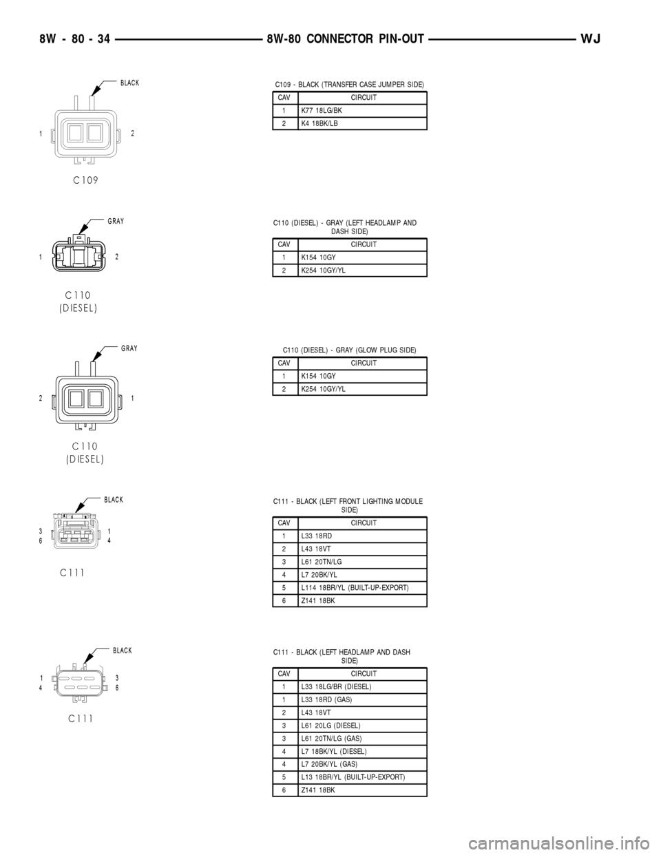
C109 - BLACK (TRANSFER CASE JUMPER SIDE)
CAV CIRCUIT
1 K77 18LG/BK
2 K4 18BK/LB
C110 (DIESEL) - GRAY (LEFT HEADLAMP AND
DASH SIDE)
CAV CIRCUIT
1 K154 10GY
2 K254 10GY/YL
C110 (DIESEL) - GRAY (GLOW PLUG SIDE)
CAV CIRCUIT
1 K154 10GY
2 K254 10GY/YL
C111 - BLACK (LEFT FRONT LIGHTING MODULE
SIDE)
CAV CIRCUIT
1 L33 18RD
2 L43 18VT
3 L61 20TN/LG
4 L7 20BK/YL
5 L114 18BR/YL (BUILT-UP-EXPORT)
6 Z141 18BK
C111 - BLACK (LEFT HEADLAMP AND DASH
SIDE)
CAV CIRCUIT
1 L33 18LG/BR (DIESEL)
1 L33 18RD (GAS)
2 L43 18VT
3 L61 20LG (DIESEL)
3 L61 20TN/LG (GAS)
4 L7 18BK/YL (DIESEL)
4 L7 20BK/YL (GAS)
5 L13 18BR/YL (BUILT-UP-EXPORT)
6 Z141 18BK
8W - 80 - 34 8W-80 CONNECTOR PIN-OUTWJ
Page 1082 of 2199
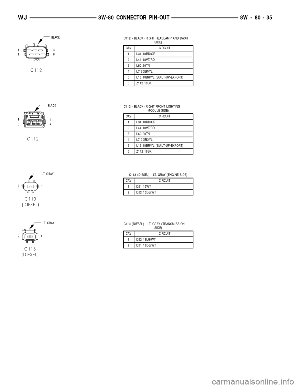
C112 - BLACK (RIGHT HEADLAMP AND DASH
SIDE)
CAV CIRCUIT
1 L34 18RD/OR
2 L44 18VT/RD
3 L60 20TN
4 L7 20BK/YL
5 L13 18BR/YL (BUILT-UP-EXPORT)
6 Z142 18BK
C112 - BLACK (RIGHT FRONT LIGHTING
MODULE SIDE)
CAV CIRCUIT
1 L34 18RD/OR
2 L44 18VT/RD
3 L60 20TN
4 L7 20BK/YL
5 L13 18BR/YL (BUILT-UP-EXPORT)
6 Z142 18BK
C113 (DIESEL) - LT. GRAY (ENGINE SIDE)
CAV CIRCUIT
1 D51 16WT
2 D52 16DG/WT
C113 (DIESEL) - LT. GRAY (TRANSMISSION
SIDE)
CAV CIRCUIT
1 D52 18LG/WT
2 D51 18DG/WT
WJ8W-80 CONNECTOR PIN-OUT 8W - 80 - 35
Page 1880 of 2199
(4) Close flip up glass panel and verify proper
operation.
(5)
Install liftgate trim panel, refer to (Refer to 23 -
BODY/DECKLID/HATCH/LIFTGATE/TAILGATE/TRIM
PANEL - INSTALLATION).
FLIP-UP GLASS LATCH
STRIKER
REMOVAL
(1) Raise flip up glass panel.
(2) Mark the position of the handle/striker on the
glass panel.
(3) Remove the screws attaching the handle/striker
to the glass.
INSTALLATION
(1) Position the handle/striker on the glass panel
and align the reference marks.
(2) Install the screws attaching the handle/striker
to the glass panel. Tighten the fasteners to 6 N´m (60
in. lbs.).
FLIP-UP GLASS SWITCH
REMOVAL
(1) Remove license plate lamp housing/trim panel
from liftgate, refer to (Refer to 8 - ELECTRICAL/
LAMPS/LIGHTING - EXTERIOR/LICENSE PLATE
LAMP UNIT - REMOVAL).
(2) Squeeze the locking tabs inward to release the
switch from the housing.
(3) Disconnect the switch harness connector,
remove the switch from the housing.
INSTALLATION
(1) Install switch harness connector.(2) Position switch in housing, snap switch into
place.
(3) Install license plate lamp housing/trim panel
onto liftgate, refer to (Refer to 8 - ELECTRICAL/
LAMPS/LIGHTING - EXTERIOR/LICENSE PLATE
LAMP UNIT - INSTALLATION).
HINGE
REMOVAL
NOTE: It is not necessary to remove the liftgate to
replace one or both hinges. The hinges can be
replaced one at a time.
(1) Open the liftgate. Support the liftgate for ease
of repair.
(2) Remove the liftgate header trim panel.
(3) Mark the hinge location with a grease pencil or
other suitable device.
(4) Remove the hinge screws (Fig. 5).
(5) Remove hinge.
INSTALLATION
NOTE: It is not necessary to remove the liftgate to
replace one or both hinges. The hinges can be
replaced one at a time.
(1) Position the hinge on the roof panel and on the
liftgate. (Use 3MŸ Fast and Firm or equivalent on
the hinge to body mating surfaces as a sealant.
(2) Install and tighten hinge screws at roof panel
to 28N´m (21 ft. lbs.).
(3) Install hinge screws at liftgate. Tighten screws
to 28N´m (21 ft. lbs.).
(4) Install liftgate header trim panel.
(5) Check the liftgate for proper alignment and
operation.
WJDECKLID/HATCH/LIFTGATE/TAILGATE 23 - 7
FLIP-UP GLASS LATCH (Continued)
Page 1881 of 2199
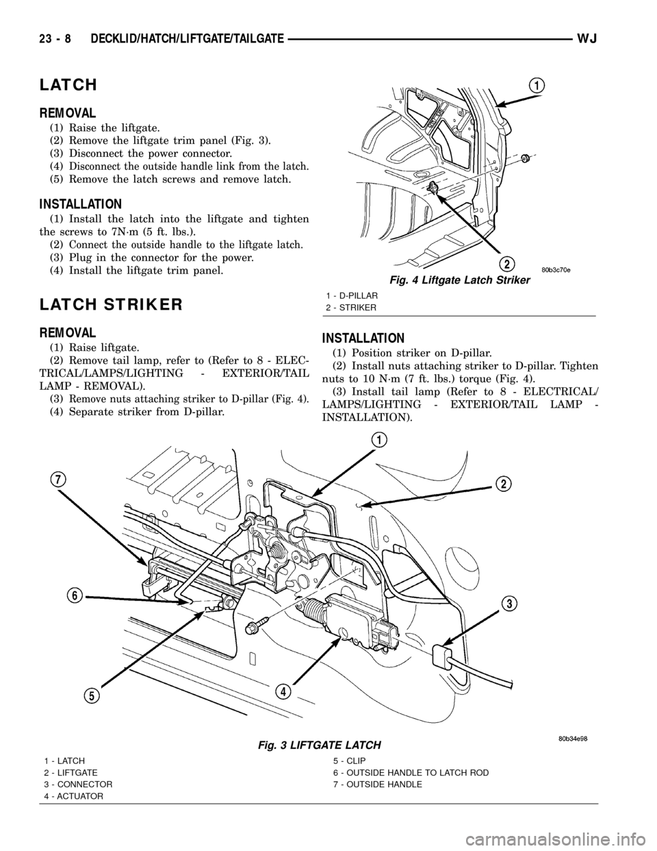
LATCH
REMOVAL
(1) Raise the liftgate.
(2) Remove the liftgate trim panel (Fig. 3).
(3) Disconnect the power connector.
(4)
Disconnect the outside handle link from the latch.
(5) Remove the latch screws and remove latch.
INSTALLATION
(1) Install the latch into the liftgate and tighten
the screws to 7N´m (5 ft. lbs.).
(2)
Connect the outside handle to the liftgate latch.
(3) Plug in the connector for the power.
(4) Install the liftgate trim panel.
LATCH STRIKER
REMOVAL
(1) Raise liftgate.
(2) Remove tail lamp, refer to (Refer to 8 - ELEC-
TRICAL/LAMPS/LIGHTING - EXTERIOR/TAIL
LAMP - REMOVAL).
(3)
Remove nuts attaching striker to D-pillar (Fig. 4).
(4) Separate striker from D-pillar.
INSTALLATION
(1) Position striker on D-pillar.
(2) Install nuts attaching striker to D-pillar. Tighten
nuts to 10 N´m (7 ft. lbs.) torque (Fig. 4).
(3) Install tail lamp (Refer to 8 - ELECTRICAL/
LAMPS/LIGHTING - EXTERIOR/TAIL LAMP -
INSTALLATION).
Fig. 3 LIFTGATE LATCH
1-LATCH
2 - LIFTGATE
3 - CONNECTOR
4 - ACTUATOR5 - CLIP
6 - OUTSIDE HANDLE TO LATCH ROD
7 - OUTSIDE HANDLE
Fig. 4 Liftgate Latch Striker
1 - D-PILLAR
2 - STRIKER
23 - 8 DECKLID/HATCH/LIFTGATE/TAILGATEWJ
Page 1900 of 2199
COWL GRILLE
REMOVAL
(1) Remove wiper arms, refer to (Refer to 8 -
ELECTRICAL/WIPERS/WASHERS/WIPER ARMS -
REMOVAL).
(2) Remove plenum seal.
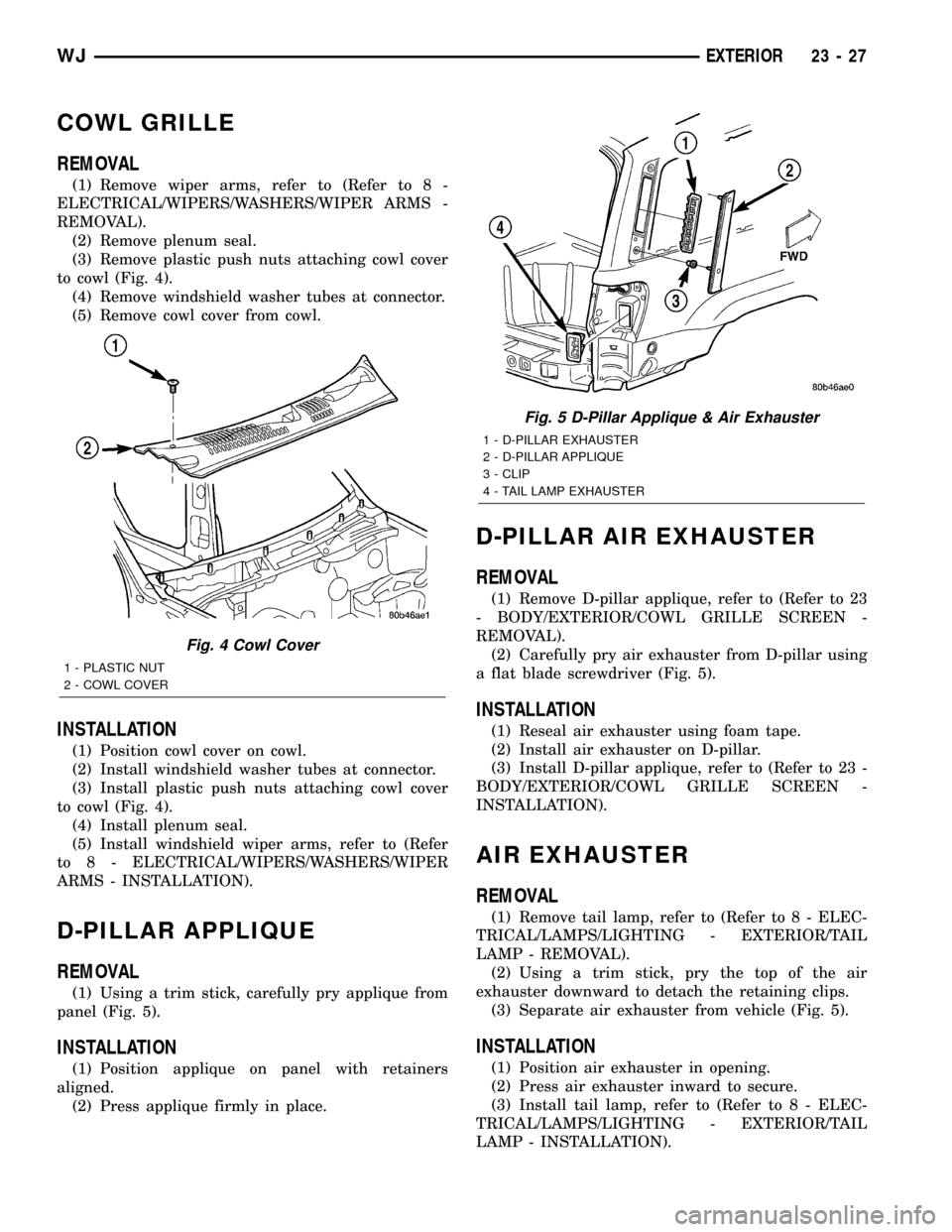
(3) Remove plastic push nuts attaching cowl cover
to cowl (Fig. 4).
(4) Remove windshield washer tubes at connector.
(5) Remove cowl cover from cowl.
INSTALLATION
(1) Position cowl cover on cowl.
(2) Install windshield washer tubes at connector.
(3) Install plastic push nuts attaching cowl cover
to cowl (Fig. 4).
(4) Install plenum seal.
(5) Install windshield wiper arms, refer to (Refer
to 8 - ELECTRICAL/WIPERS/WASHERS/WIPER
ARMS - INSTALLATION).
D-PILLAR APPLIQUE
REMOVAL
(1) Using a trim stick, carefully pry applique from
panel (Fig. 5).
INSTALLATION
(1) Position applique on panel with retainers
aligned.
(2) Press applique firmly in place.
D-PILLAR AIR EXHAUSTER
REMOVAL
(1) Remove D-pillar applique, refer to (Refer to 23
- BODY/EXTERIOR/COWL GRILLE SCREEN -
REMOVAL).
(2) Carefully pry air exhauster from D-pillar using
a flat blade screwdriver (Fig. 5).
INSTALLATION
(1) Reseal air exhauster using foam tape.
(2) Install air exhauster on D-pillar.
(3) Install D-pillar applique, refer to (Refer to 23 -
BODY/EXTERIOR/COWL GRILLE SCREEN -
INSTALLATION).
AIR EXHAUSTER
REMOVAL
(1) Remove tail lamp, refer to (Refer to 8 - ELEC-
TRICAL/LAMPS/LIGHTING - EXTERIOR/TAIL
LAMP - REMOVAL).
(2) Using a trim stick, pry the top of the air
exhauster downward to detach the retaining clips.
(3) Separate air exhauster from vehicle (Fig. 5).
INSTALLATION
(1) Position air exhauster in opening.
(2) Press air exhauster inward to secure.
(3) Install tail lamp, refer to (Refer to 8 - ELEC-
TRICAL/LAMPS/LIGHTING - EXTERIOR/TAIL
LAMP - INSTALLATION).
Fig. 4 Cowl Cover
1 - PLASTIC NUT
2 - COWL COVER
Fig. 5 D-Pillar Applique & Air Exhauster
1 - D-PILLAR EXHAUSTER
2 - D-PILLAR APPLIQUE
3 - CLIP
4 - TAIL LAMP EXHAUSTER
WJEXTERIOR 23 - 27