2002 JEEP GRAND CHEROKEE fuse panel fuse 23
[x] Cancel search: fuse panel fuse 23Page 647 of 2199

(2) Pull the rear washer nozzle out from the lift-
gate outer panel far enough to access the washer
supply hose (Fig. 4).
(3) Disconnect the washer supply hose from the
barbed nipple of the rear washer nozzle.
(4) Remove the rear washer nozzle from the lift-
gate.
INSTALLATION
(1) Position the rear washer nozzle to the liftgate
(Fig. 4).
(2) Reconnect the washer supply hose to the
barbed nipple of the rear washer nozzle.
(3) Insert the rear washer nozzle supply hose and
nipple into the mounting hole in the liftgate outer
panel.
(4) Using hand pressure, push firmly and evenly
on the rear washer nozzle until the snap features
lock into place on the inside of the liftgate outer
panel mounting hole.
REAR WASHER PUMP/MOTOR
DESCRIPTION
The rear washer pump/motor unit is located on the
outboard side and near the rear of the washer reser-
voir, between the left front inner and outer fender
panels (Fig. 5). A small permanently lubricated and
sealed electric motor is coupled to the rotor-type
washer pump. A seal flange with a large barbed inlet
nipple on the pump housing passes through a rubber
grommet seal installed in one of two dedicatedmounting holes near the bottom of the washer reser-
voir. The rear washer pump/motor unit is always
mounted in the higher pump mounting hole of the
reservoir. A smaller barbed outlet nipple on the pump
housing connects the unit to the rear washer hose.
The washer pump/motor unit is retained on the res-
ervoir by the interference fit between the barbed
pump inlet nipple and the grommet seal, which is a
light press fit. An integral electrical connector recep-
tacle is located on the top of the motor housing. The
rear washer pump/motor unit cannot be repaired. If
faulty or damaged, the entire washer pump/motor
unit must be replaced.
OPERATION
The rear washer pump/motor unit is connected to
the vehicle electrical system through a single take
out and two-cavity connector of the left headlamp
and dash wire harness. The washer pump/motor is
grounded at all times through a take out of the left
headlamp and dash wire harness with a single eyelet
terminal connector that is secured under a ground
screw to the top of the left inner fender shield in the
engine compartment. The rear washer pump/motor
receives battery current on a fused ignition switch
output (run-acc) circuit through the closed contacts of
the momentary rear washer switch within the right
multi-function switch only when the switch control
stalk is pushed towards the instrument panel.
Washer fluid is gravity-fed from the washer reservoir
to the inlet side of the washer pump. When the pump
motor is energized, the rotor-type pump pressurizes
Fig. 4 Rear Washer Nozzle Remove/Install
1 - HEADLINER WASHER HOSE
2 - ROOF PANEL
3 - REAR WASHER NOZZLE
4 - LIFTGATE
Fig. 5 Washer Pumps (Viewed from Bottom of
Reservoir)
1 - REAR WASHER PUMP/MOTOR
2 - FRONT WASHER PUMP/MOTOR
3 - WASHER FLUID LEVEL SWITCH
8R - 40 REAR WIPERS/WASHERSWJ
REAR WASHER NOZZLE (Continued)
Page 652 of 2199

motor that is secured with screws to the wiper motor
and to the liftgate inner panel.
²Electronic Controls- The rear wiper module
electronic controls include the rear wiper system
electronic logic and rear wiper motor electronic con-
trols. The electronic controls for the motor include an
electronic speed control that speeds the wiper blade
near the center of the glass, but slows the wiper
blade during directional reversals at each end of the
wipe pattern and during wiper blade off-the-glass
parking for quieter operation.
²Motor- The permanent magnet rear wiper
motor is secured with screws to the rear wiper mod-
ule bracket. The wiper motor includes an integral
transmission, and the motor output shaft.
The rear wiper module cannot be adjusted or
repaired. If any component of the module is faulty or
damaged, the entire rear wiper module unit must be
replaced. The motor output shaft gasket, bezel, nut,
and nut cover are available for service replacement.
OPERATION
The rear wiper module receives non-switched bat-
tery current through a fuse in the Junction Block
(JB) and is grounded at all times. The rear wiper
module operation is controlled by the vehicle operator
through battery current signal inputs received by the
rear wiper module electronic controls from the right
multi-function switch on the steering column. The
module also receives an external control input from
the liftgate flip-up glass ajar switch circuit. The rear
wiper module electronic control logic uses these
inputs, its internal inputs, and its programming to
provide continuous wipe, delay wipe, wipe-after-wash
and off-the-glass wiper blade parking. The wiper
blade cycling is controlled by the rear wiper module
electronic controls, which control current flow to the
wiper motor brushes. The wiper motor transmission
converts the rotary output of the wiper motor to the
back and forth wiping motion of the rear wiper arm
and blade on the liftgate glass.
REMOVAL
(1) Disconnect and isolate the battery negative
cable.
(2) Remove the rear wiper arm from the rear
wiper motor output shaft. (Refer to 8 - ELECTRI-
CAL/REAR WIPERS/WASHERS/REAR WIPER ARM
- REMOVAL).
(3) Use a door trim panel removal tool to gently
pry at the base of the nut cover where it meets the
wiper motor output shaft bezel and gasket on the
outer liftgate panel until it unsnaps from the bezel
(Fig. 13). Be certain to use proper caution to protect
the outer liftgate panel and its paint finish from
damage during this procedure.(4) Remove the nut that secures the rear wiper
motor output shaft to the outer liftgate panel.
(5) Remove the bezel and gasket from the rear
wiper motor output shaft.
(6) Remove the trim panel from the inside of the
liftgate. (Refer to 23 - BODY/DECKLID/HATCH/
LIFTGATE/TAILGATE/TRIM PANEL - REMOVAL).
(7) Disconnect the liftgate wire harness connector
for the rear wiper module from the module connector
receptacle (Fig. 14).
(8) Loosen the two nuts that secure the rear wiper
module mounting bracket to the liftgate inner panel.
(9) Slide the rear wiper module and mounting
bracket forward far enough to disengage the mount-
ing nuts from the keyed holes in the liftgate inner
panel.
(10) Remove the rear wiper module and mounting
bracket from the liftgate as a unit.
INSTALLATION
(1) Position the rear wiper module and bracket to
the liftgate as a unit (Fig. 14).
(2) Insert the rear wiper motor output shaft
through the hole in the liftgate outer panel and
engage the mounting nuts in the keyed holes in the
liftgate inner panel.
(3) From the outside of the liftgate, center the rear
wiper motor output shaft in the liftgate outer panel
mounting hole and install the gasket and bezel over
the centered shaft (Fig. 13).
Fig. 13 Rear Wiper Motor Output Shaft Remove/
Install
1 - NUT
2 - NUT COVER
3 - BEZEL AND GASKET
4 - LIFTGATE OUTER PANEL
5 - REAR WIPER MOTOR OUTPUT SHAFT
WJREAR WIPERS/WASHERS 8R - 45
REAR WIPER MODULE (Continued)
Page 932 of 2199

8W-47 AUDIO SYSTEM
Component Page
Antenna........................... 8W-47-2
Antenna Module..................... 8W-47-3
Body Control Module............. 8W-47-2, 3, 13
Clockspring........................ 8W-47-13
Compact Disc Changer.............. 8W-47-6, 7
Diagnostic Junction Port...... 8W-47-2, 3, 6, 7, 13
Fuse 5........................... 8W-47-2, 3
Fuse 30.......................... 8W-47-2, 3
G300............................ 8W-47-2, 3
Junction Block.................... 8W-47-2, 3Component Page
Left Front Door Speaker......... 8W-47-4, 10, 11
Left Instrument Panel Speaker....... 8W-47-4, 12
Left Rear Door Speaker.......... 8W-47-5, 10, 11
Left Remote Radio Switch............. 8W-47-13
Power Amplifier..... 8W-47-3, 6, 7, 8, 9, 10, 11, 12
Radio............. 8W-47-2, 3, 4, 5, 6, 7, 8, 9, 13
Right Front Door Speaker........ 8W-47-4, 10, 11
Right Instrument Panel Speaker..... 8W-47-4, 12
Right Rear Door Speaker......... 8W-47-5, 10, 11
Right Remote Radio Switch........... 8W-47-13
WJ8W-47 AUDIO SYSTEM 8W - 47 - 1
Page 1056 of 2199
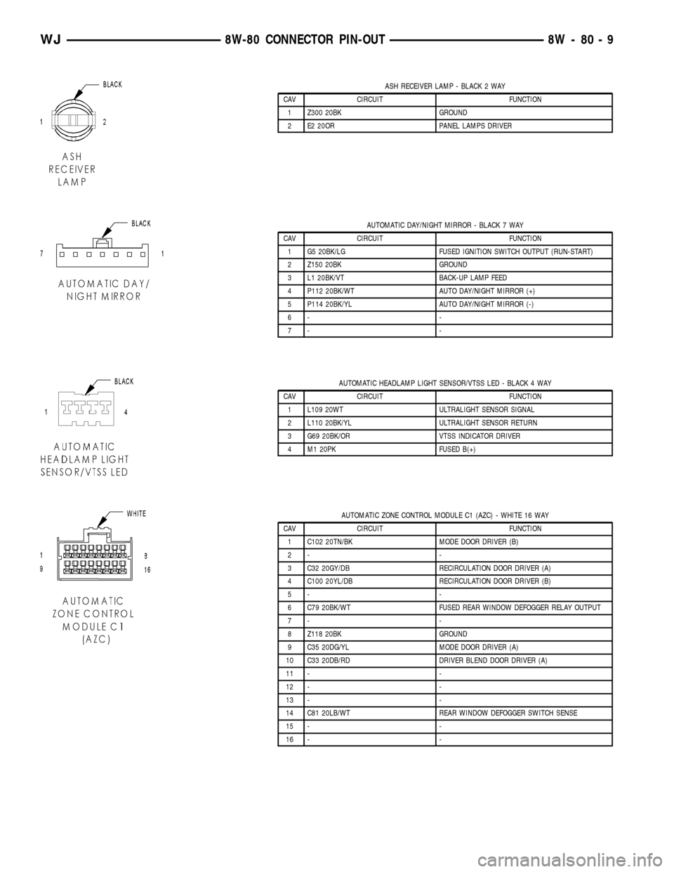
ASH RECEIVER LAMP - BLACK 2 WAY
CAV CIRCUIT FUNCTION
1 Z300 20BK GROUND
2 E2 20OR PANEL LAMPS DRIVER
AUTOMATIC DAY/NIGHT MIRROR - BLACK 7 WAY
CAV CIRCUIT FUNCTION
1 G5 20BK/LG FUSED IGNITION SWITCH OUTPUT (RUN-START)
2 Z150 20BK GROUND
3 L1 20BK/VT BACK-UP LAMP FEED
4 P112 20BK/WT AUTO DAY/NIGHT MIRROR (+)
5 P114 20BK/YL AUTO DAY/NIGHT MIRROR (-)
6- -
7- -
AUTOMATIC HEADLAMP LIGHT SENSOR/VTSS LED - BLACK 4 WAY
CAV CIRCUIT FUNCTION
1 L109 20WT ULTRALIGHT SENSOR SIGNAL
2 L110 20BK/YL ULTRALIGHT SENSOR RETURN
3 G69 20BK/OR VTSS INDICATOR DRIVER
4 M1 20PK FUSED B(+)
AUTOMATIC ZONE CONTROL MODULE C1 (AZC) - WHITE 16 WAY
CAV CIRCUIT FUNCTION
1 C102 20TN/BK MODE DOOR DRIVER (B)
2- -
3 C32 20GY/DB RECIRCULATION DOOR DRIVER (A)
4 C100 20YL/DB RECIRCULATION DOOR DRIVER (B)
5- -
6 C79 20BK/WT FUSED REAR WINDOW DEFOGGER RELAY OUTPUT
7- -
8 Z118 20BK GROUND
9 C35 20DG/YL MODE DOOR DRIVER (A)
10 C33 20DB/RD DRIVER BLEND DOOR DRIVER (A)
11 - -
12 - -
13 - -
14 C81 20LB/WT REAR WINDOW DEFOGGER SWITCH SENSE
15 - -
16 - -
WJ8W-80 CONNECTOR PIN-OUT 8W - 80 - 9
Page 1057 of 2199
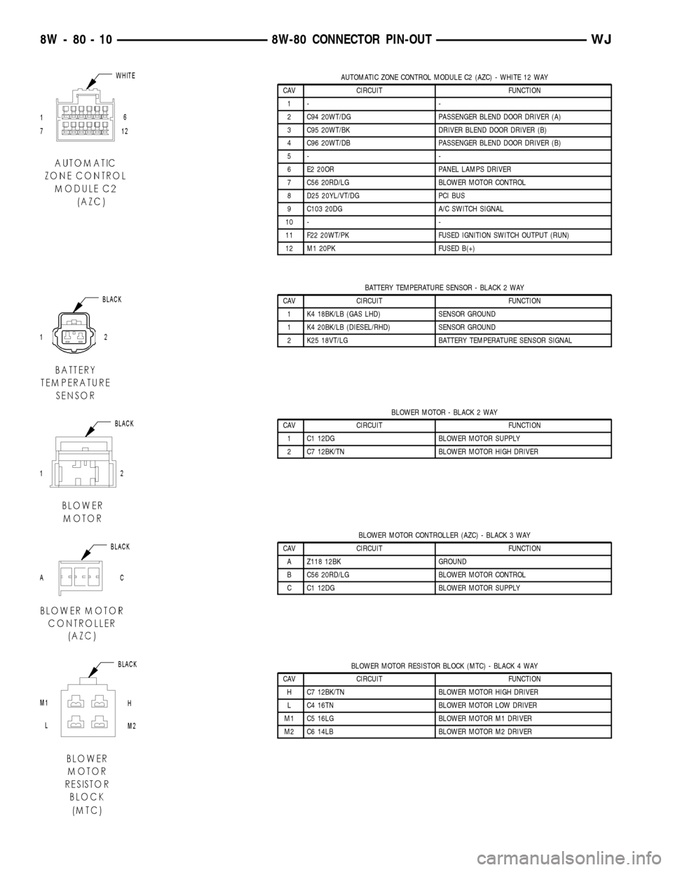
AUTOMATIC ZONE CONTROL MODULE C2 (AZC) - WHITE 12 WAY
CAV CIRCUIT FUNCTION
1- -
2 C94 20WT/DG PASSENGER BLEND DOOR DRIVER (A)
3 C95 20WT/BK DRIVER BLEND DOOR DRIVER (B)
4 C96 20WT/DB PASSENGER BLEND DOOR DRIVER (B)
5- -
6 E2 20OR PANEL LAMPS DRIVER
7 C56 20RD/LG BLOWER MOTOR CONTROL
8 D25 20YL/VT/DG PCI BUS
9 C103 20DG A/C SWITCH SIGNAL
10 - -
11 F22 20WT/PK FUSED IGNITION SWITCH OUTPUT (RUN)
12 M1 20PK FUSED B(+)
BATTERY TEMPERATURE SENSOR - BLACK 2 WAY
CAV CIRCUIT FUNCTION
1 K4 18BK/LB (GAS LHD) SENSOR GROUND
1 K4 20BK/LB (DIESEL/RHD) SENSOR GROUND
2 K25 18VT/LG BATTERY TEMPERATURE SENSOR SIGNAL
BLOWER MOTOR - BLACK 2 WAY
CAV CIRCUIT FUNCTION
1 C1 12DG BLOWER MOTOR SUPPLY
2 C7 12BK/TN BLOWER MOTOR HIGH DRIVER
BLOWER MOTOR CONTROLLER (AZC) - BLACK 3 WAY
CAV CIRCUIT FUNCTION
A Z118 12BK GROUND
B C56 20RD/LG BLOWER MOTOR CONTROL
C C1 12DG BLOWER MOTOR SUPPLY
BLOWER MOTOR RESISTOR BLOCK (MTC) - BLACK 4 WAY
CAV CIRCUIT FUNCTION
H C7 12BK/TN BLOWER MOTOR HIGH DRIVER
L C4 16TN BLOWER MOTOR LOW DRIVER
M1 C5 16LG BLOWER MOTOR M1 DRIVER
M2 C6 14LB BLOWER MOTOR M2 DRIVER
8W - 80 - 10 8W-80 CONNECTOR PIN-OUTWJ
Page 1117 of 2199
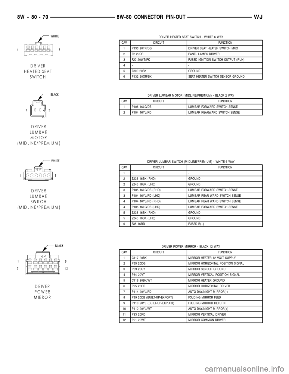
DRIVER HEATED SEAT SWITCH - WHITE 6 WAY
CAV CIRCUIT FUNCTION
1 P133 20TN/DG DRIVER SEAT HEATER SWITCH MUX
2 E2 20OR PANEL LAMPS DRIVER
3 F22 20WT/PK FUSED IGNITION SWITCH OUTPUT (RUN)
4- -
5 Z300 20BK GROUND
6 P132 20OR/BK SEAT HEATER SWITCH SENSOR GROUND
DRIVER LUMBAR MOTOR (MIDLINE/PREMIUM) - BLACK 2 WAY
CAV CIRCUIT FUNCTION
1 P105 16LG/DB LUMBAR FORWARD SWITCH SENSE
2 P104 16YL/RD LUMBAR REARWARD SWITCH SENSE
DRIVER LUMBAR SWITCH (MIDLINE/PREMIUM) - WHITE 6 WAY
CAV CIRCUIT FUNCTION
1- -
2 Z238 16BK (RHD) GROUND
2 Z243 16BK (LHD) GROUND
3 P105 16LG/DB (RHD) LUMBAR FORWARD SWITCH SENSE
3 P104 16YL/RD (LHD) LUMBAR REAR WARD SWITCH SENSE
4 P104 16YL/RD (RHD) LUMBAR REAR WARD SWITCH SENSE
4 P105 16LG/DB (LHD) LUMBAR FORWARD SWITCH SENSE
5 Z238 16BK (RHD) GROUND
5 Z243 16BK (LHD) GROUND
6 F35 16RD FUSED B(+)
DRIVER POWER MIRROR - BLACK 12 WAY
CAV CIRCUIT FUNCTION
1 C117 20BK MIRROR HEATER 12 VOLT SUPPLY
2 P65 20DG MIRROR HORIZONTAL POSITION SIGNAL
3 P69 20GY MIRROR SENSOR GROUND
4 P64 20VT MIRROR VERTICAL POSITION SIGNAL
5 C118 20BK/WT MIRROR HEATER GROUND
6 P95 20OR MIRROR HORIZONTAL DRIVER
7 P114 20YL/RD AUTO DAY/NIGHT MIRROR(-)
8 P99 20DB (BUILT-UP-EXPORT) FOLDING MIRROR FEED
9 P110 20YL (BUILT-UP-EXPORT) FOLDING MIRROR RETURN
10 P112 20YL/WT AUTO DAY/NIGHT MIRROR(+)
11 P93 20RD MIRROR VERTICAL DRIVER
12 P91 20WT MIRROR COMMON DRIVER
8W - 80 - 70 8W-80 CONNECTOR PIN-OUTWJ
Page 1141 of 2199
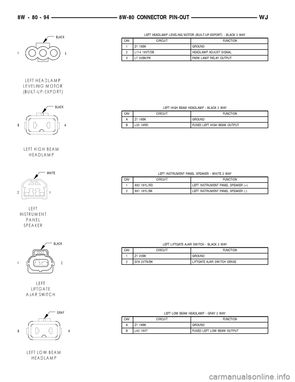
LEFT HEADLAMP LEVELING MOTOR (BUILT-UP-EXPORT) - BLACK 3 WAY
CAV CIRCUIT FUNCTION
1 Z1 18BK GROUND
2 L114 18VT/DB HEADLAMP ADJUST SIGNAL
3 L7 20BK/PK PARK LAMP RELAY OUTPUT
LEFT HIGH BEAM HEADLAMP - BLACK 2 WAY
CAV CIRCUIT FUNCTION
A Z1 18BK GROUND
B L33 18RD FUSED LEFT HIGH BEAM OUTPUT
LEFT INSTRUMENT PANEL SPEAKER - WHITE 2 WAY
CAV CIRCUIT FUNCTION
1 X83 18YL/RD LEFT INSTRUMENT PANEL SPEAKER (+)
2 X81 18YL/BK LEFT INSTRUMENT PANEL SPEAKER (-)
LEFT LIFTGATE AJAR SWITCH - BLACK 2 WAY
CAV CIRCUIT FUNCTION
1 Z1 20BK GROUND
2 G78 20TN/BK LIFTGATE AJAR SWITCH SENSE
LEFT LOW BEAM HEADLAMP - GRAY 2 WAY
CAV CIRCUIT FUNCTION
A Z1 18BK GROUND
B L43 18VT FUSED LEFT LOW BEAM OUTPUT
8W - 80 - 94 8W-80 CONNECTOR PIN-OUTWJ
Page 1145 of 2199
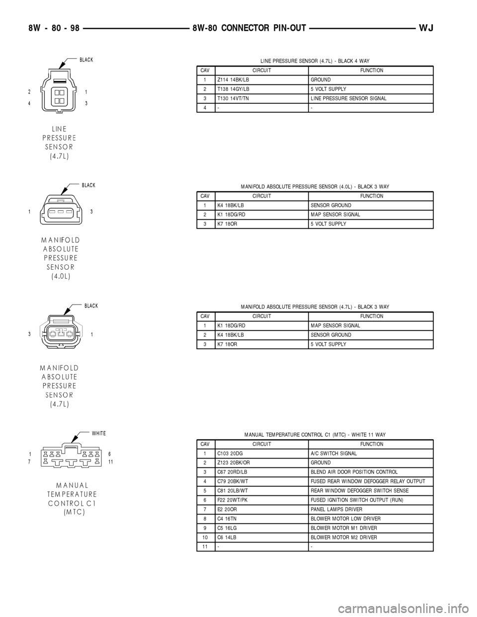
LINE PRESSURE SENSOR (4.7L) - BLACK 4 WAY
CAV CIRCUIT FUNCTION
1 Z114 14BK/LB GROUND
2 T138 14GY/LB 5 VOLT SUPPLY
3 T130 14VT/TN LINE PRESSURE SENSOR SIGNAL
4- -
MANIFOLD ABSOLUTE PRESSURE SENSOR (4.0L) - BLACK 3 WAY
CAV CIRCUIT FUNCTION
1 K4 18BK/LB SENSOR GROUND
2 K1 18DG/RD MAP SENSOR SIGNAL
3 K7 18OR 5 VOLT SUPPLY
MANIFOLD ABSOLUTE PRESSURE SENSOR (4.7L) - BLACK 3 WAY
CAV CIRCUIT FUNCTION
1 K1 18DG/RD MAP SENSOR SIGNAL
2 K4 18BK/LB SENSOR GROUND
3 K7 18OR 5 VOLT SUPPLY
MANUAL TEMPERATURE CONTROL C1 (MTC) - WHITE 11 WAY
CAV CIRCUIT FUNCTION
1 C103 20DG A/C SWITCH SIGNAL
2 Z123 20BK/OR GROUND
3 C67 20RD/LB BLEND AIR DOOR POSITION CONTROL
4 C79 20BK/WT FUSED REAR WINDOW DEFOGGER RELAY OUTPUT
5 C81 20LB/WT REAR WINDOW DEFOGGER SWITCH SENSE
6 F22 20WT/PK FUSED IGNITION SWITCH OUTPUT (RUN)
7 E2 20OR PANEL LAMPS DRIVER
8 C4 16TN BLOWER MOTOR LOW DRIVER
9 C5 16LG BLOWER MOTOR M1 DRIVER
10 C6 14LB BLOWER MOTOR M2 DRIVER
11 - -
8W - 80 - 98 8W-80 CONNECTOR PIN-OUTWJ