2002 JEEP GRAND CHEROKEE Motor mount
[x] Cancel search: Motor mountPage 1256 of 2199

INSTALLATION
CAUTION: When installing the engine into a vehicle
equipped with an automatic transmission, be care-
ful not to damage the trigger wheel on the engine
flywheel.
(1) Attach a lifting device to the engine and lower
the engine into the engine compartment. For easier
installation, it may be necessary to remove the
engine mount bracket as an aid in alignment of the
engine to the transmission.
(2) Align the transmission torque converter hous-
ing with the engine.
(3) Loosely install the converter housing lower
bolts and install the next higher bolt and nut on each
side.
(4) Tighten all 4 bolts finger tight.
(5) Install the engine mount brackets (if removed).
(6) Lower the engine and engine mount brackets
onto the engine compartment cushions. Install the
bolts and finger tighten the nuts.
(7) Remove the engine lifting device.
(8) Raise and support the vehicle.
(9) Install the remaining engine flywheel/converter
housing bolts. Tighten all bolts to 38 N´m (28 ft. lbs.)
torque.
(10) Install the converter-to-drive plate bolts.
(11) Ensure the installation reference marks are
aligned.
(12) Install the engine flywheel/converter housing
access cover.
(13) Install the exhaust pipe support and tighten
the screw.
(14) Install the engine bending brace (Refer to 9 -
ENGINE/ENGINE BLOCK/STRUCT SUPPORT -
INSTALLATION).
(15) Tighten the engine mount-to-bracket bolts.
(16) Connect the vehicle speed sensor wire connec-
tions and tighten the screws.
(17) Connect the exhaust pipe to the manifold.
(18) Install the engine starter motor (Refer to 8 -
ELECTRICAL/STARTING/STARTER MOTOR -
INSTALLATION).
(19) Connect the wires to the engine starter motor
solenoid.
(20) Lower the vehicle.
(21) Connect all the vacuum hoses and wire con-
nectors identified during engine removal.
(22) Remove protective caps from the power steer-
ing hoses.
(23) Connect the hoses to the fittings at the steer-
ing gear. Tighten the nut to 52 N´m (38 ft. lbs.)
torque.
(24) Fill the pump reservoir with fluid.(25) Inspect the fuel supply line o-ring(s) and
replace if necessary. Connect fuel supply line to injec-
tior rail and verify connection by pulling outward on
the line.
(26) Install the fuel line bracket to the intake
manifold.
(27) Connect the coil rail electrical connectors and
oil pressure switch connector.
(28) Connect the following electrical connectors:
²Power steering pressure switch
²Coolant temperature sensor
²Six (6) fuel injector connectors
²Intake air temperature sensor
²Throttle position sensor
²Map sensor
²Crankshaft position sensor
²Oxygen sensor
²Camshaft position sensor
²Generator connector and B+ terminal wire
(29) Connect all previously removed vacuum hoses.
(30) Connect the body ground strap.
(31) Install the throttle, transmission line pres-
sure, and speed control cables to their mounting
bracket and connect them to the throttle body.
(32) Connect the heater hoses at the engine ther-
mostat housing and water pump.
(33) Install the fan assembly (Refer to 7 - COOL-
ING/ENGINE/RADIATOR FAN - INSTALLATION).
(34) Place the fan shroud in position over the fan.
(35) Install the radiator (Refer to 7 - COOLING/
ENGINE/RADIATOR - INSTALLATION).
(36) Connect the service valves to the A/C com-
pressor ports, if equipped with A/C.
(37) Charge the air conditioner system (Refer to 24
- HEATING & AIR CONDITIONING/PLUMBING -
STANDARD PROCEDURE).
(38) Connect the radiator hoses and automatic
transmission fluid cooler pipes, if equipped.
(39) Install the fan shroud to the radiator or radi-
ator/condenser (if equipped with A/C).
(40) Install upper radiator support.
(41) Connect the upper radiator hose and tighten
the clamp.
(42) Connect the lower radiator hose and tighten
the clamp.
(43) Fill crankcase with engine oil. (Refer to
LUBRICATION & MAINTENANCE/FLUID CAPACI-
TIES - SPECIFICATIONS) for correct capacities.
(44) Fill the cooling system with reusable coolant
or new coolant (Refer to 7 - COOLING - STANDARD
PROCEDURE).
(45) Align the hood to the scribe marks. Install the
hood.
(46) Install the air cleaner assembly.
(47) Install the battery and connect the battery
cable.
WJENGINE - 4.0L 9 - 13
ENGINE - 4.0L (Continued)
Page 1261 of 2199
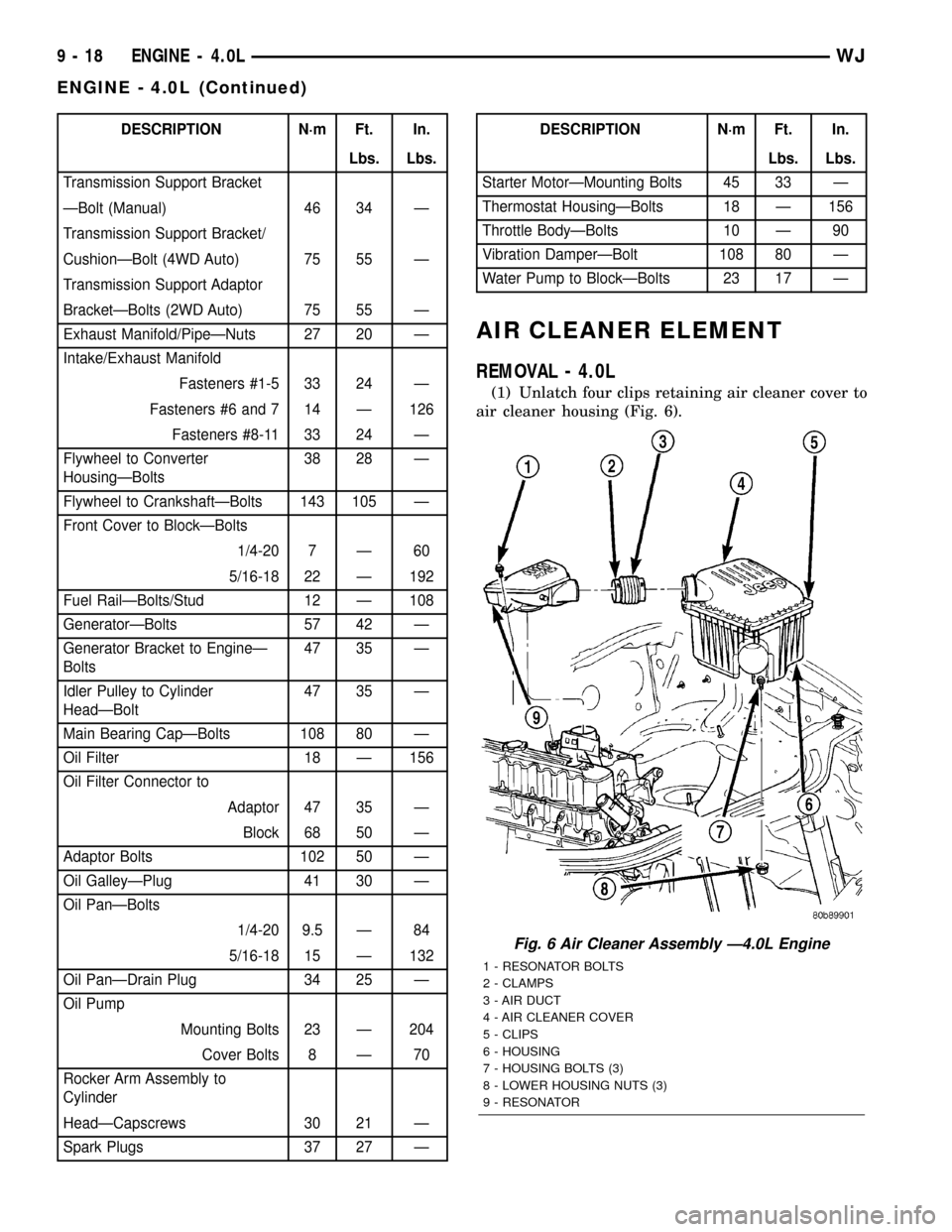
DESCRIPTION N´m Ft. In.
Lbs. Lbs.
Transmission Support Bracket
ÐBolt (Manual) 46 34 Ð
Transmission Support Bracket/
CushionÐBolt (4WD Auto) 75 55 Ð
Transmission Support Adaptor
BracketÐBolts (2WD Auto) 75 55 Ð
Exhaust Manifold/PipeÐNuts 27 20 Ð
Intake/Exhaust Manifold
Fasteners #1-5 33 24 Ð
Fasteners #6 and 7 14 Ð 126
Fasteners #8-11 33 24 Ð
Flywheel to Converter
HousingÐBolts38 28 Ð
Flywheel to CrankshaftÐBolts 143 105 Ð
Front Cover to BlockÐBolts
1/4-20 7 Ð 60
5/16-18 22 Ð 192
Fuel RailÐBolts/Stud 12 Ð 108
GeneratorÐBolts 57 42 Ð
Generator Bracket to EngineÐ
Bolts47 35 Ð
Idler Pulley to Cylinder
HeadÐBolt47 35 Ð
Main Bearing CapÐBolts 108 80 Ð
Oil Filter 18 Ð 156
Oil Filter Connector to
Adaptor 47 35 Ð
Block 68 50 Ð
Adaptor Bolts 102 50 Ð
Oil GalleyÐPlug 41 30 Ð
Oil PanÐBolts
1/4-20 9.5 Ð 84
5/16-18 15 Ð 132
Oil PanÐDrain Plug 34 25 Ð
Oil Pump
Mounting Bolts 23 Ð 204
Cover Bolts 8 Ð 70
Rocker Arm Assembly to
Cylinder
HeadÐCapscrews 30 21 Ð
Spark Plugs 37 27 ÐDESCRIPTION N´m Ft. In.
Lbs. Lbs.
Starter MotorÐMounting Bolts 45 33 Ð
Thermostat HousingÐBolts 18 Ð 156
Throttle BodyÐBolts 10 Ð 90
Vibration DamperÐBolt 108 80 Ð
Water Pump to BlockÐBolts 23 17 Ð
AIR CLEANER ELEMENT
REMOVAL - 4.0L
(1) Unlatch four clips retaining air cleaner cover to
air cleaner housing (Fig. 6).
Fig. 6 Air Cleaner Assembly Ð4.0L Engine
1 - RESONATOR BOLTS
2 - CLAMPS
3 - AIR DUCT
4 - AIR CLEANER COVER
5 - CLIPS
6 - HOUSING
7 - HOUSING BOLTS (3)
8 - LOWER HOUSING NUTS (3)
9 - RESONATOR
9 - 18 ENGINE - 4.0LWJ
ENGINE - 4.0L (Continued)
Page 1299 of 2199
(9) Lower the engine until it is properly located on
the engine mounts.
(10) Install the through bolts and tighten the nuts.
(11) Lower the jack stand and remove the piece of
wood.
(12) Install the engine flywheel and transmission
torque converter housing access cover.
(13) Install the engine starter motor. (Refer to 8 -
ELECTRICAL/STARTING/STARTER MOTOR -
INSTALLATION).
(14) Connect the exhaust pipe to the hanger and to
the engine exhaust manifold.
(15) Install transmission oil cooling lines (if
equipped) and oxygen sensor wiring supports that
attach to the oil pan studs.
(16) Install the oil pan drain plug (Fig. 81).
Tighten the plug to 34 N´m (25 ft. lbs.) torque.
(17) Lower the vehicle.
(18) Connect negative cable to battery.
(19) Fill the oil pan with engine oil to the specified
level.
WARNING: USE EXTREME CAUTION WHEN THE
ENGINE IS OPERATING. DO NOT STAND IN A
DIRECT LINE WITH THE FAN. DO NOT PUT YOUR
HANDS NEAR THE PULLEYS, BELTS OR FAN. DO
NOT WEAR LOOSE CLOTHING.
(20) Start the engine and inspect for leaks.
ENGINE OIL PRESSURE
SENSOR
DESCRIPTION
The 3±wire, solid-state engine oil pressure sensor
(sending unit) is located in an engine oil pressure
gallery.
OPERATION
The oil pressure sensor uses three circuits. They
are:
²A 5±volt power supply from the Powertrain Con-
trol Module (PCM)
²A sensor ground through the PCM's sensor
return
²A signal to the PCM relating to engine oil pres-
sure
The oil pressure sensor has a 3±wire electrical
function very much like the Manifold Absolute Pres-
sure (MAP) sensor. Meaning different pressures
relate to different output voltages.
A 5±volt supply is sent to the sensor from the PCM
to power up the sensor. The sensor returns a voltage
signal back to the PCM relating to engine oil pres-
sure. This signal is then transferred (bussed) to theinstrument panel on either a CCD or PCI bus circuit
(depending on vehicle line) to operate the oil pressure
gauge and the check gauges lamp. Ground for the
sensor is provided by the PCM through a low-noise
sensor return.
OIL PUMP
REMOVAL
A gear-type oil pump is mounted at the underside
of the cylinder block opposite the No.4 main bearing.
(1) Drain the engine oil.
(2) Remove the oil pan (Refer to 9 - ENGINE/LU-
BRICATION/OIL PAN - REMOVAL).
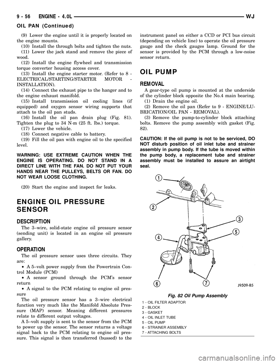
(3) Remove the pump-to-cylinder block attaching
bolts. Remove the pump assembly with gasket (Fig.
82).
CAUTION: If the oil pump is not to be serviced, DO
NOT disturb position of oil inlet tube and strainer
assembly in pump body. If the tube is moved within
the pump body, a replacement tube and strainer
assembly must be installed to assure an airtight
seal.
Fig. 82 Oil Pump Assembly
1 - OIL FILTER ADAPTOR
2 - BLOCK
3 - GASKET
4 - OIL INLET TUBE
5 - OIL PUMP
6 - STRAINER ASSEMBLY
7 - ATTACHING BOLTS
9 - 56 ENGINE - 4.0LWJ
OIL PAN (Continued)
Page 1300 of 2199

INSTALLATION
A gear-type oil pump is mounted at the underside
of the cylinder block opposite the No.4 main bearing.
(1) Install the oil pump on the cylinder block using
a replacement gasket. Tighten the bolts to 23 N´m
(17 ft. lbs.) torque.
(2) Install the oil pan (Refer to 9 - ENGINE/LU-
BRICATION/OIL PAN - INSTALLATION).
(3) Fill the oil pan with oil to the specified level.
INTAKE MANIFOLD
DESCRIPTION
The intake manifold (Fig. 83) is made of cast alu-
minum and uses eleven bolts to mount to the cylin-
der head. This mounting style improves sealing and
reduces the chance of leaks.
DIAGNOSIS AND TESTING - INTAKE
MANIFOLD LEAKAGE
An intake manifold air leak is characterized by
lower than normal manifold vacuum. Also, one or
more cylinders may not be functioning.
WARNING: USE EXTREME CAUTION WHEN THE
ENGINE IS OPERATING. DO NOT STAND IN A
DIRECT LINE WITH THE FAN. DO NOT PUT YOUR
HANDS NEAR THE PULLEYS, BELTS OR THE FAN.
DO NOT WEAR LOOSE CLOTHING.
(1) Start the engine.
(2) Spray a small stream of water at the suspected
leak area.
(3) If a change in RPM is observed the area of the
suspected leak has been found.
(4) Repair as required.
REMOVAL
NOTE: THE ENGINE INTAKE AND EXHAUST MANI-
FOLD MUST BE REMOVED AND INSTALLED
TOGETHER. THE MANIFOLDS USE A COMMON
GASKET AT THE CYLINDER HEAD.
(1) Disconnect the battery negative cable.
(2) Remove air cleaner inlet hose from the resona-
tor assembly.
(3) Remove the air cleaner assembly.
(4) Remove the throttle cable, vehicle speed control
cable (if equipped) and the transmission line pres-
sure cable (Refer to 21 - TRANSMISSION/TRANS-
AXLE/AUTOMATIC - AW4/THROTTLE VALVE
CABLE - REMOVAL).
(5) Disconnect the following electrical connections
and secure their harness out of the way:
²Throttle Position Sensor
²Idle Air Control Motor
²Coolant Temperature Sensor (at thermostat
housing)
²Intake Air Temperature Sensor
²Oxygen Sensor
²Crank Position Sensor
²Six (6) Fuel Injector Connectors
²Manifold Absolute Pressure (MAP) Sensor.
(6) Disconnect HVAC, and Brake Booster vacuum
supply hoses at the intake manifold.
(7) Perform the fuel pressure release procedure.
(Refer to 14 - FUEL SYSTEM/FUEL DELIVERY -
STANDARD PROCEDURE).
(8) Disconnect and remove the fuel system supply
line from the fuel rail assembly.
(9) Remove the accessory drive belt (Refer to 7 -
COOLING/ACCESSORY DRIVE/DRIVE BELTS -
REMOVAL).
(10) Remove the power steering pump from the
intake manifold and set aside.
(11) Raise the vehicle.
(12) Disconnect the exhaust pipes from the engine
exhaust manifolds.
(13) Lower the vehicle.
(14) Remove the intake manifold and exhaust
manifold bolts and manifolds (Fig. 84).
INSTALLATION
If the manifold is being replaced, ensure all the fit-
ting, etc. are transferred to the replacement mani-
fold.
(1) Install a new engine exhaust/intake manifold
gasket over the alignment dowels on the cylinder
head.
(2) Position the engine exhaust manifolds to the
cylinder head. Install fastener Number 3 and finger
tighten at this time (Fig. 84).
Fig. 83 Intake Manifold 4.0L Engine
WJENGINE - 4.0L 9 - 57
OIL PUMP (Continued)
Page 1314 of 2199
²Abrasive pad or paper to clean cylinder block
and head
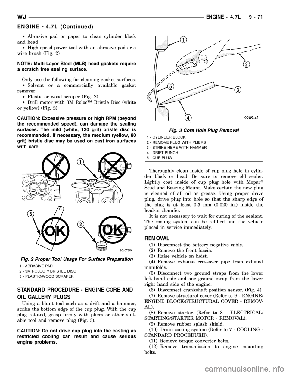
²High speed power tool with an abrasive pad or a
wire brush (Fig. 2)
NOTE: Multi-Layer Steel (MLS) head gaskets require
a scratch free sealing surface.
Only use the following for cleaning gasket surfaces:
²Solvent or a commercially available gasket
remover
²Plastic or wood scraper (Fig. 2)
²Drill motor with 3M RolocŸ Bristle Disc (white
or yellow) (Fig. 2)
CAUTION: Excessive pressure or high RPM (beyond
the recommended speed), can damage the sealing
surfaces. The mild (white, 120 grit) bristle disc is
recommended. If necessary, the medium (yellow, 80
grit) bristle disc may be used on cast iron surfaces
with care.
STANDARD PROCEDURE - ENGINE CORE AND
OIL GALLERY PLUGS
Using a blunt tool such as a drift and a hammer,
strike the bottom edge of the cup plug. With the cup
plug rotated, grasp firmly with pliers or other suit-
able tool and remove plug (Fig. 3).
CAUTION: Do not drive cup plug into the casting as
restricted cooling can result and cause serious
engine problems.Thoroughly clean inside of cup plug hole in cylin-
der block or head. Be sure to remove old sealer.
Lightly coat inside of cup plug hole with Mopart
Stud and Bearing Mount. Make certain the new plug
is cleaned of all oil or grease. Using proper drive
plug, drive plug into hole so that the sharp edge of
the plug is at least 0.5 mm (0.020 in.) inside the
lead-in chamfer.
It is not necessary to wait for curing of the sealant.
The cooling system can be refilled and the vehicle
placed in service immediately.
REMOVAL
(1) Disconnect the battery negative cable.
(2) Remove the front fascia.
(3) Raise vehicle on hoist.
(4) Remove exhaust crossover pipe from exhaust
manifolds.
(5) Disconnect two ground straps from the lower
left hand side and one ground strap from the lower
right hand side of the engine.
(6) Disconnect crankshaft position sensor. (Fig. 4)
(7) Remove structural cover (Refer to 9 - ENGINE/
ENGINE BLOCK/STRUCTURAL COVER - REMOV-
AL).
(8) Remove starter. (Refer to 8 - ELECTRICAL/
STARTING/STARTER MOTOR - REMOVAL).
(9) Remove rubber splash shield.
(10) Drain cooling system (Refer to 7 - COOLING -
STANDARD PROCEDURE).
(11) Remove torque converter bolts.
(12) Remove transmission to engine mounting
bolts.
Fig. 2 Proper Tool Usage For Surface Preparation
1 - ABRASIVE PAD
2 - 3M ROLOCŸ BRISTLE DISC
3 - PLASTIC/WOOD SCRAPER
Fig. 3 Core Hole Plug Removal
1 - CYLINDER BLOCK
2 - REMOVE PLUG WITH PLIERS
3 - STRIKE HERE WITH HAMMER
4 - DRIFT PUNCH
5 - CUP PLUG
WJENGINE - 4.7L 9 - 71
ENGINE - 4.7L (Continued)
Page 1316 of 2199
(32) Disconnect body ground strap at the right side
cowl.
NOTE: It will be necessary to support the transmis-
sion in order to remove the engine.
(33) Position a suitable jack under the transmis-
sion.
(34) Remove the engine mount through bolts.
(35) Raise engine slightly, then remove both left
and right side engine mounts from engine. (Refer to
9 - ENGINE/ENGINE MOUNTING/FRONT MOUNT
- REMOVAL).
(36) Remove engine from the vehicle.
INSTALLATION
(1) Position engine in the vehicle.
(2) Install both left and right side engine mounts
onto engine (Refer to 9 - ENGINE/ENGINE MOUNT-
ING/FRONT MOUNT - INSTALLATION).
(3) Install transmission to engine mounting bolts.
Tighten the bolts to 41 N´m (30 ft. lbs.).(4) Remove jack from under the transmission.
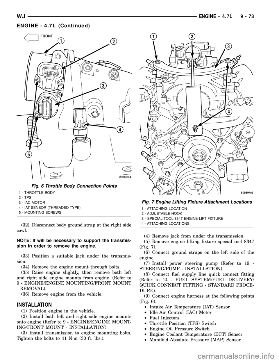
(5) Remove engine lifting fixture special tool 8347
(Fig. 7).
(6) Connect ground straps on the left side of the
engine.
(7) Install power steering pump (Refer to 19 -
STEERING/PUMP - INSTALLATION).
(8) Connect fuel supply line quick connect fitting
(Refer to 14 - FUEL SYSTEM/FUEL DELIVERY/
QUICK CONNECT FITTING - STANDARD PROCE-
DURE).
(9) Connect engine harness at the following points
(Fig. 6):
²Intake Air Temperature (IAT) Sensor
²Idle Air Control (IAC) Motor
²Fuel Injectors
²Throttle Position (TPS) Switch
²Engine Oil Pressure Switch
²Engine Coolant Temperature (ECT) Sensor
²Manifold Absolute Pressure (MAP) Sensor
Fig. 6 Throttle Body Connection Points
1 - THROTTLE BODY
2 - TPS
3 - IAC MOTOR
4 - IAT SENSOR (THREADED TYPE)
5 - MOUNTING SCREWS
Fig. 7 Engine Lifting Fixture Attachment Locations
1 - ATTACHING LOCATION
2 - ADJUSTABLE HOOK
3 - SPECIAL TOOL 8347 ENGINE LIFT FIXTURE
4 - ATTACHING LOCATIONS
WJENGINE - 4.7L 9 - 73
ENGINE - 4.7L (Continued)
Page 1375 of 2199
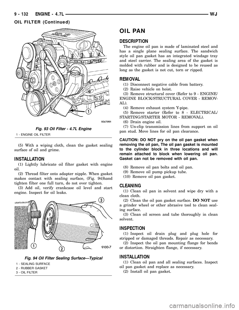
(5) With a wiping cloth, clean the gasket sealing
surface of oil and grime.
INSTALLATION
(1) Lightly lubricate oil filter gasket with engine
oil.
(2) Thread filter onto adapter nipple. When gasket
makes contact with sealing surface, (Fig. 94)hand
tighten filter one full turn, do not over tighten.
(3) Add oil, verify crankcase oil level and start
engine. Inspect for oil leaks.
OIL PAN
DESCRIPTION
The engine oil pan is made of laminated steel and
has a single plane sealing surface. The sandwich
style oil pan gasket has an integrated windage tray
and steel carrier. The sealing area of the gasket is
molded with rubber and is designed to be reused as
long as the gasket is not cut, torn or ripped.
REMOVAL
(1) Disconnect negative cable from battery.
(2) Raise vehicle on hoist.
(3) Remove structural cover (Refer to 9 - ENGINE/
ENGINE BLOCK/STRUCTURAL COVER - REMOV-
AL).
(4) Remove exhaust system Y-pipe.
(5) Remove starter (Refer to 8 - ELECTRICAL/
STARTING/STARTER MOTOR - REMOVAL).
(6) Drain engine oil.
(7) Un-clip transmission lines from support on oil
pan stud. Move lines for oil pan clearance.
CAUTION: DO NOT pry on the oil pan gasket when
removing the oil pan, The oil pan gasket is mounted
to the cylinder block in three locations and will
remain attached to block when lowering oil pan.
Gasket can not be removed with oil pan.
(8) Remove oil pan bolts and oil pan.
(9) Remove oil pump pickup tube.
(10) Remove oil pan gasket.
CLEANING
(1) Clean oil pan in solvent and wipe dry with a
clean cloth.
(2) Clean the oil pan gasket surface.DO NOTuse
a grinder wheel or other abrasive tool to clean seal-
ing surface.
(3) Clean oil screen and tube thoroughly in clean
solvent.
INSPECTION
(1) Inspect oil drain plug and plug hole for
stripped or damaged threads. Repair as necessary.
(2) Inspect the oil pan mounting flange for bends
or distortion. Straighten flange, if necessary.
INSTALLATION
(1) Clean oil pan and all sealing surfaces. Inspect
oil pan gasket and replace as necessary.
(2) Install oil pan gasket.
Fig. 93 Oil Filter - 4.7L Engine
1 - ENGINE OIL FILTER
Fig. 94 Oil Filter Sealing SurfaceÐTypical
1 - SEALING SURFACE
2 - RUBBER GASKET
3 - OIL FILTER
9 - 132 ENGINE - 4.7LWJ
OIL FILTER (Continued)
Page 1376 of 2199

NOTE: When installing oil pan gasket/windage tray,
start four pan bolts at each corner before tightening
oil pickup tube. This will keep pan gasket in align-
ment.
(3) Install oil pump pick-up tube using a new
O-ring. First tighten bolt at O-ring end of tube to 28
N´m (20 ft. lbs.). Tighten remain tube support fasten-
ers to 28 N´m (20 ft. lbs.).
(4) Install oil pan and tighten fasteners to 15 N´m
(11 ft. lbs.) (Fig. 95).
(5) Reconnect transmission oil cooler lines to oil
pan stud bolt.
(6) Install starter (Refer to 8 - ELECTRICAL/
STARTING/STARTER MOTOR - INSTALLATION).
(7) Install exhaust system Y-pipe.
(8) Install structural cover (Refer to 9 - ENGINE/
ENGINE BLOCK/STRUCTURAL COVER - INSTAL-
LATION).
(9) Lower vehicle.
(10) Fill engine with proper amount of oil (Refer to
LUBRICATION & MAINTENANCE/FLUID TYPES -
SPECIFICATIONS).
(11) Connect negative cable to battery.
OIL PRESSURE SENSOR/
SWITCH
DESCRIPTION
The 3±wire, solid-state engine oil pressure sensor
(sending unit) is located in an engine oil pressure
gallery.
OPERATION
The oil pressure sensor uses three circuits. They are:
²A 5±volt power supply from the Powertrain Con-
trol Module (PCM)
²A sensor ground through the PCM's sensor
return
²
A signal to the PCM relating to engine oil pressure
The oil pressure sensor has a 3±wire electrical
function very much like the Manifold Absolute Pres-
sure (MAP) sensor. Meaning different pressures
relate to different output voltages.
A 5±volt supply is sent to the sensor from the PCM
to power up the sensor. The sensor returns a voltage
signal back to the PCM relating to engine oil pres-
sure. This signal is then transferred (bussed) to the
instrument panel on either a CCD or PCI bus circuit
(depending on vehicle line) to operate the oil pressure
gauge and the check gauges lamp. Ground for the
sensor is provided by the PCM through a low-noise
sensor return.
REMOVAL
(1) Disconnect the negative cable from the battery.
(2) Raise vehicle on hoist.
(3) Remove front splash shield.
(4) Disconnect oil pressure sender wire (Fig. 96).
(5) Remove the pressure sender (Fig. 96).
INSTALLATION
(1) Install oil pressure sender.
(2) Connect oil pressure sender wire.
(3) Install front splash shield.
(4) Lower vehicle.
(5) Connect the negative battery cable.
Fig. 95 Oil Pan Tightening Sequence
Fig. 96 Oil Pressure Sending Unit
1 - BELT
2 - OIL PRESSURE SENSOR
3 - OIL FILTER
4 - ELEC. CONNECTOR
WJENGINE - 4.7L 9 - 133
OIL PAN (Continued)