2002 JEEP GRAND CHEROKEE Fuel
[x] Cancel search: FuelPage 1178 of 2199
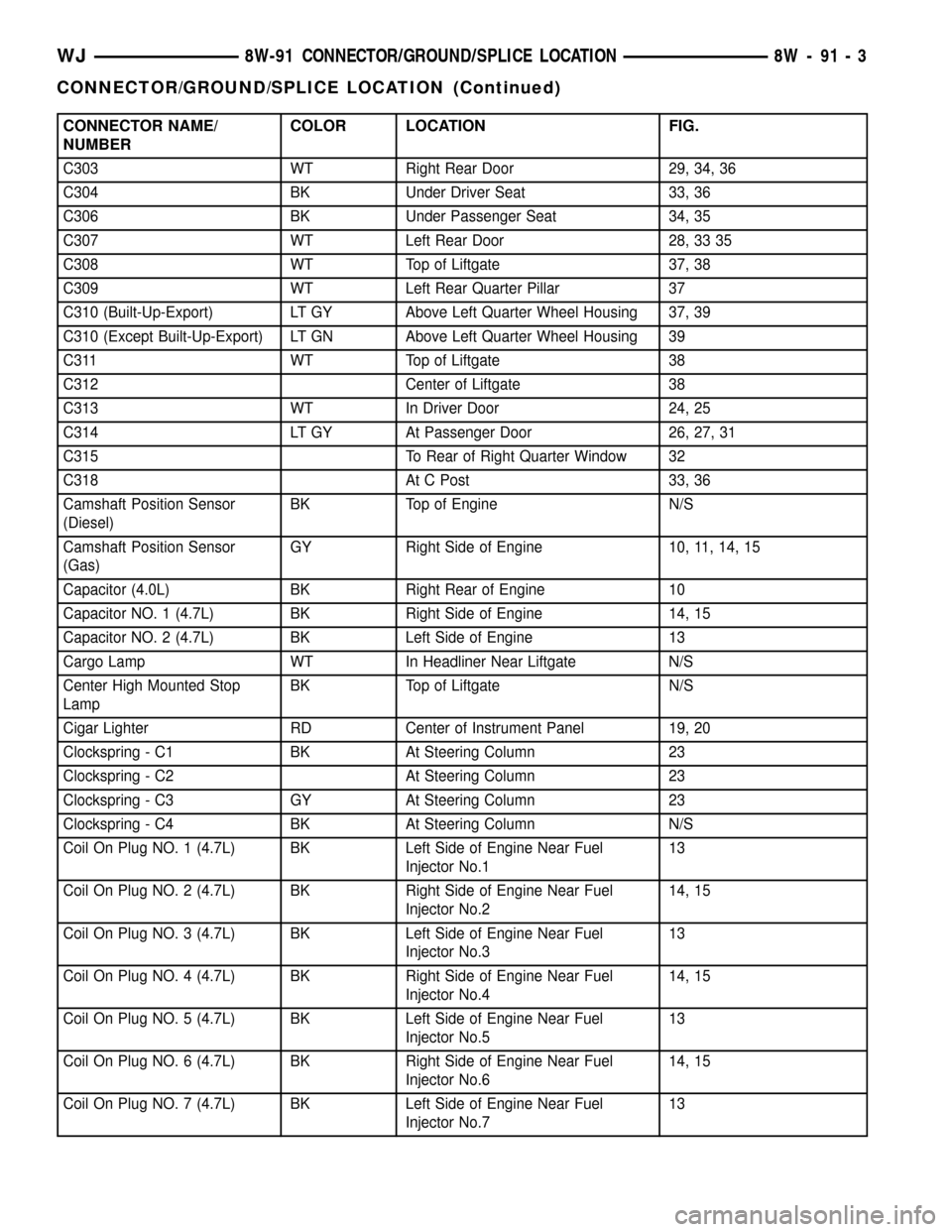
CONNECTOR NAME/
NUMBERCOLOR LOCATION FIG.
C303 WT Right Rear Door 29, 34, 36
C304 BK Under Driver Seat 33, 36
C306 BK Under Passenger Seat 34, 35
C307 WT Left Rear Door 28, 33 35
C308 WT Top of Liftgate 37, 38
C309 WT Left Rear Quarter Pillar 37
C310 (Built-Up-Export) LT GY Above Left Quarter Wheel Housing 37, 39
C310 (Except Built-Up-Export) LT GN Above Left Quarter Wheel Housing 39
C311 WT Top of Liftgate 38
C312 Center of Liftgate 38
C313 WT In Driver Door 24, 25
C314 LT GY At Passenger Door 26, 27, 31
C315 To Rear of Right Quarter Window 32
C318 At C Post 33, 36
Camshaft Position Sensor
(Diesel)BK Top of Engine N/S
Camshaft Position Sensor
(Gas)GY Right Side of Engine 10, 11, 14, 15
Capacitor (4.0L) BK Right Rear of Engine 10
Capacitor NO. 1 (4.7L) BK Right Side of Engine 14, 15
Capacitor NO. 2 (4.7L) BK Left Side of Engine 13
Cargo Lamp WT In Headliner Near Liftgate N/S
Center High Mounted Stop
LampBK Top of Liftgate N/S
Cigar Lighter RD Center of Instrument Panel 19, 20
Clockspring - C1 BK At Steering Column 23
Clockspring - C2 At Steering Column 23
Clockspring - C3 GY At Steering Column 23
Clockspring - C4 BK At Steering Column N/S
Coil On Plug NO. 1 (4.7L) BK Left Side of Engine Near Fuel
Injector No.113
Coil On Plug NO. 2 (4.7L) BK Right Side of Engine Near Fuel
Injector No.214, 15
Coil On Plug NO. 3 (4.7L) BK Left Side of Engine Near Fuel
Injector No.313
Coil On Plug NO. 4 (4.7L) BK Right Side of Engine Near Fuel
Injector No.414, 15
Coil On Plug NO. 5 (4.7L) BK Left Side of Engine Near Fuel
Injector No.513
Coil On Plug NO. 6 (4.7L) BK Right Side of Engine Near Fuel
Injector No.614, 15
Coil On Plug NO. 7 (4.7L) BK Left Side of Engine Near Fuel
Injector No.713
WJ8W-91 CONNECTOR/GROUND/SPLICE LOCATION 8W - 91 - 3
CONNECTOR/GROUND/SPLICE LOCATION (Continued)
Page 1179 of 2199
CONNECTOR NAME/
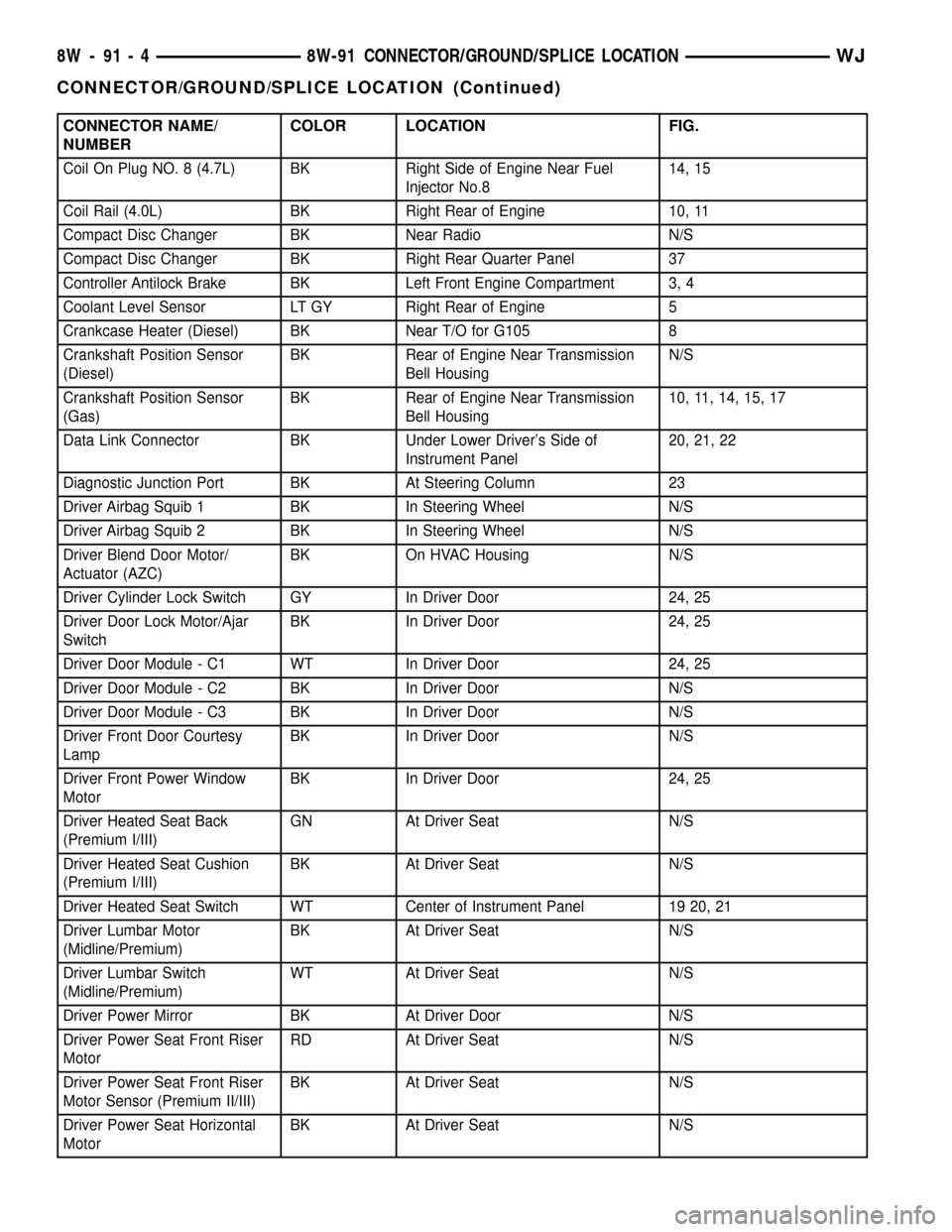
NUMBERCOLOR LOCATION FIG.
Coil On Plug NO. 8 (4.7L) BK Right Side of Engine Near Fuel
Injector No.814, 15
Coil Rail (4.0L) BK Right Rear of Engine 10, 11
Compact Disc Changer BK Near Radio N/S
Compact Disc Changer BK Right Rear Quarter Panel 37
Controller Antilock Brake BK Left Front Engine Compartment 3, 4
Coolant Level Sensor LT GY Right Rear of Engine 5
Crankcase Heater (Diesel) BK Near T/O for G105 8
Crankshaft Position Sensor
(Diesel)BK Rear of Engine Near Transmission
Bell HousingN/S
Crankshaft Position Sensor
(Gas)BK Rear of Engine Near Transmission
Bell Housing10, 11, 14, 15, 17
Data Link Connector BK Under Lower Driver's Side of
Instrument Panel20, 21, 22
Diagnostic Junction Port BK At Steering Column 23
Driver Airbag Squib 1 BK In Steering Wheel N/S
Driver Airbag Squib 2 BK In Steering Wheel N/S
Driver Blend Door Motor/
Actuator (AZC)BK On HVAC Housing N/S
Driver Cylinder Lock Switch GY In Driver Door 24, 25
Driver Door Lock Motor/Ajar
SwitchBK In Driver Door 24, 25
Driver Door Module - C1 WT In Driver Door 24, 25
Driver Door Module - C2 BK In Driver Door N/S
Driver Door Module - C3 BK In Driver Door N/S
Driver Front Door Courtesy
LampBK In Driver Door N/S
Driver Front Power Window
MotorBK In Driver Door 24, 25
Driver Heated Seat Back
(Premium I/III)GN At Driver Seat N/S
Driver Heated Seat Cushion
(Premium I/III)BK At Driver Seat N/S
Driver Heated Seat Switch WT Center of Instrument Panel 19 20, 21
Driver Lumbar Motor
(Midline/Premium)BK At Driver Seat N/S
Driver Lumbar Switch
(Midline/Premium)WT At Driver Seat N/S
Driver Power Mirror BK At Driver Door N/S
Driver Power Seat Front Riser
MotorRD At Driver Seat N/S
Driver Power Seat Front Riser
Motor Sensor (Premium II/III)BK At Driver Seat N/S
Driver Power Seat Horizontal
MotorBK At Driver Seat N/S
8W - 91 - 4 8W-91 CONNECTOR/GROUND/SPLICE LOCATIONWJ
CONNECTOR/GROUND/SPLICE LOCATION (Continued)
Page 1180 of 2199
CONNECTOR NAME/
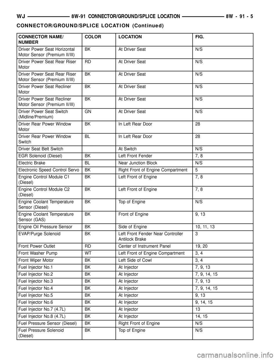
NUMBERCOLOR LOCATION FIG.
Driver Power Seat Horizontal
Motor Sensor (Premium II/III)BK At Driver Seat N/S
Driver Power Seat Rear Riser
MotorRD At Driver Seat N/S
Driver Power Seat Rear Riser
Motor Sensor (Premium II/III)BK At Driver Seat N/S
Driver Power Seat Recliner
MotorBK At Driver Seat N/S
Driver Power Seat Recliner
Motor Sensor (Premium II/III)BK At Driver Seat N/S
Driver Power Seat Switch
(Midline/Premium)GN At Driver Seat N/S
Driver Rear Power Window
MotorBK In Left Rear Door 28
Driver Rear Power Window
SwitchBL In Left Rear Door 28
Driver Seat Belt Switch At Switch N/S
EGR Solenoid (Diesel) BK Left Front Fender 7, 8
Electric Brake BL Near Junction Block N/S
Electronic Speed Control Servo BK Right Front of Engine Compartment 5
Engine Control Module C1
(Diesel)BK Left Front of Engine 7, 8
Engine Control Module C2
(Diesel)BK Left Front of Engine 7, 8
Engine Coolant Temperature
Sensor (Diesel)BK Top of Engine N/S
Engine Coolant Temperature
Sensor (GAS)BK Front of Engine 9, 13
Engine Oil Pressure Sensor BK Side of Engine 10, 11, 13
EVAP/Purge Solenoid BK Left Front Fender Near Controller
Antilock Brake3
Front Power Outlet RD Center of Instrument Panel 19, 20
Front Washer Pump WT Left Front of Engine Compartment 3, 4
Front Wiper Motor BK Left Side of Cowl 3, 4
Fuel Injector No.1 BK At Injector 7, 9, 13
Fuel Injector No.2 BK At Injector 7, 9, 14, 15
Fuel Injector No.3 BK At Injector 7, 9, 13
Fuel Injector No.4 BK At Injector 7, 9, 14, 15
Fuel Injector No.5 BK At Injector 9, 13
Fuel Injector No.6 BK At Injector 9, 14, 15
Fuel Injector No.7 (4.7L) BK At Injector 13
Fuel Injector No.8 (4.7L) BK At Injector 14, 15
Fuel Pressure Sensor (Diesel) BK Right Front of Engine N/S
Fuel Pressure Solenoid
(Diesel)BK Top of Engine N/S
WJ8W-91 CONNECTOR/GROUND/SPLICE LOCATION 8W - 91 - 5
CONNECTOR/GROUND/SPLICE LOCATION (Continued)
Page 1181 of 2199
CONNECTOR NAME/
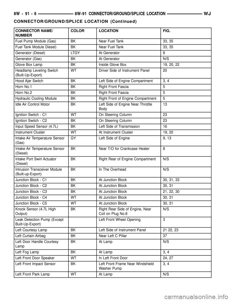
NUMBERCOLOR LOCATION FIG.
Fuel Pump Module (Gas) BK Near Fuel Tank 33, 35
Fuel Tank Module Diesel) BK Near Fuel Tank 33, 35
Generator (Diesel) LTGY At Generator 8
Generator (Gas) BK At Generator N/S
Glove Box Lamp BK Inside Glove Box 19, 20, 22
Headlamp Leveling Switch
(Built-Up-Export)WT Driver Side of Instrument Panel 20
Hood Ajar Switch BK Left Side of Engine Compartment 3, 4
Horn No.1 BK Right Front Fascia 5
Horn No.2 BK Right Front Fascia 5
Hydraulic Cooling Module BK Right Front of Engine Compartment 5
Idle Air Control Motor BK Left Side of Engine Near Throttle
Body13
Ignition Switch - C1 WT On Steering Column 23
Ignition Switch - C2 BK On Steering Column 23
Input Speed Sensor (4.7L) BK Left Side of Transmission 16
Instrument Cluster WT At Instrument Cluster 19, 20
Intake Air Temperature Sensor
(Gas)GY Left Side of Engine 9, 13
Intake Air Temperature Sensor
(Diesel)BK Near T/O for Crankcase Heater 8
Intake Port Swirl Actuator
(Diesel)BK Right Rear of Engine Compartment N/S
Intrusion Transceiver Module
(Built-up-Export)BK In The Overhead N/S
Junction Block - C1 BK At Junction Block 30, 31, 33
Junction Block - C2 BK At Junction Block 30, 31
Junction Block - C3 BK At Junction Block 21, 22, 30
Junction Block - C4 WT At Junction Block 30, 31
Junction Block - C5 WT At Junction Block 30, 31
Knock Sensor (4.7L High
Output)BK Right Rear Side of Engine, Near
Coil on Plug No.8N/S
Leak Detection Pump (Except
Built-Up-Export)Left Front Wheel Opening 3
Left Courtesy Lamp BK Left Side of Instrument Panel 21 22, 23
Left Curtain Airbag BK Near Left C Pillar 37
Left Door Handle Courtesy
LampBK At Lamp N/S
Left Fog Lamp BK At Lamp 3, 4
Left Front Door Speaker WT In Left Front Door 24, 27
Left Front Impact Sensor BK Left Front Frame Near Windshield
Washer Pump3, 4
Left Front Park Lamp WT At Lamp N/S
8W - 91 - 6 8W-91 CONNECTOR/GROUND/SPLICE LOCATIONWJ
CONNECTOR/GROUND/SPLICE LOCATION (Continued)
Page 1186 of 2199
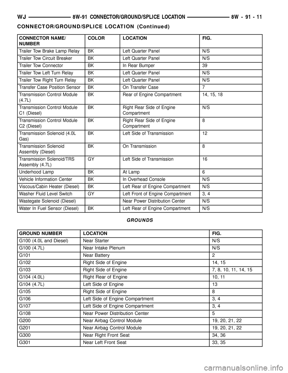
CONNECTOR NAME/
NUMBERCOLOR LOCATION FIG.
Trailer Tow Brake Lamp Relay BK Left Quarter Panel N/S
Trailer Tow Circuit Breaker BK Left Quarter Panel N/S
Trailer Tow Connector BK In Rear Bumper 39
Trailer Tow Left Turn Relay BK Left Quarter Panel N/S
Trailer Tow Right Turn Relay BK Left Quarter Panel N/S
Transfer Case Position Sensor BK On Transfer Case 7
Transmission Control Module
(4.7L)BK Rear of Engine Compartment 14, 15, 18
Transmission Control Module
C1 (Diesel)BK Right Rear Side of Engine
CompartmentN/S
Transmission Control Module
C2 (Diesel)BK Right Rear Side of Engine
Compartment8
Transmission Solenoid (4.0L
Gas)BK Left Side of Transmission 12
Transmission Solenoid
Assembly (Diesel)BK On Transmission 8
Transmission Solenoid/TRS
Assembly (4.7L)GY Left Side of Transmission 16
Underhood Lamp BK At Lamp 6
Vehicle Information Center BK In Overhead Console N/S
Viscous/Cabin Heater (Diesel) BK Left Rear of Engine Compartment N/S
Washer Fluid Level Switch GY Left Front of Engine Compartment 3, 4
Wastegate Solenoid (Diesel) Near Power Distribution Center N/S
Water In Fuel Sensor (Diesel) BK Left Rear of Engine Compartment N/S
GROUNDS
GROUND NUMBER LOCATION FIG.
G100 (4.0L and Diesel) Near Starter N/S
G100 (4.7L) Near Intake Plenum N/S
G101 Near Battery 2
G102 Right Side of Engine 14, 15
G103 Right Side of Engine 7, 8, 10, 11, 14, 15
G104 (4.0L) Right Rear of Engine 10, 11
G104 (4.7L) Left Side of Engine 13
G105 Right Side of Engine 8
G106 Left Side of Engine Compartment 3, 4
G107 Left Side of Engine Compartment 3, 4
G108 Near Power Distribution Center 5
G200 Near Airbag Control Module 19, 20, 21, 22
G201 Near Airbag Control Module 19, 20, 21, 22
G300 Near Right Front Seat 34, 36
G301 Near Left Front Seat 33, 35
WJ8W-91 CONNECTOR/GROUND/SPLICE LOCATION 8W - 91 - 11
CONNECTOR/GROUND/SPLICE LOCATION (Continued)
Page 1187 of 2199
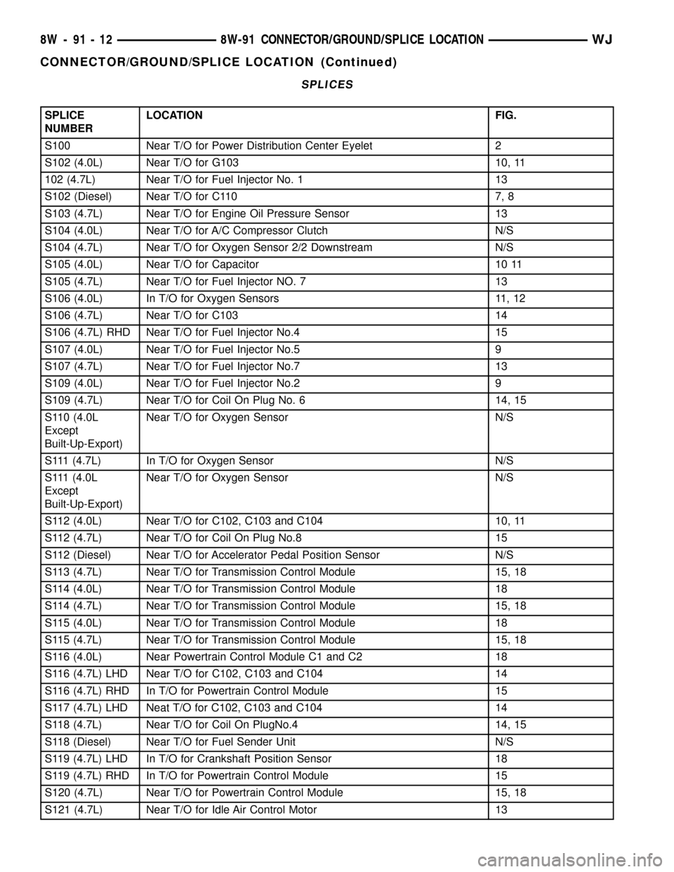
SPLICES
SPLICE
NUMBERLOCATION FIG.
S100 Near T/O for Power Distribution Center Eyelet 2
S102 (4.0L) Near T/O for G103 10, 11
102 (4.7L) Near T/O for Fuel Injector No. 1 13
S102 (Diesel) Near T/O for C110 7, 8
S103 (4.7L) Near T/O for Engine Oil Pressure Sensor 13
S104 (4.0L) Near T/O for A/C Compressor Clutch N/S
S104 (4.7L) Near T/O for Oxygen Sensor 2/2 Downstream N/S
S105 (4.0L) Near T/O for Capacitor 10 11
S105 (4.7L) Near T/O for Fuel Injector NO. 7 13
S106 (4.0L) In T/O for Oxygen Sensors 11, 12
S106 (4.7L) Near T/O for C103 14
S106 (4.7L) RHD Near T/O for Fuel Injector No.4 15
S107 (4.0L) Near T/O for Fuel Injector No.5 9
S107 (4.7L) Near T/O for Fuel Injector No.7 13
S109 (4.0L) Near T/O for Fuel Injector No.2 9
S109 (4.7L) Near T/O for Coil On Plug No. 6 14, 15
S110 (4.0L
Except
Built-Up-Export)Near T/O for Oxygen Sensor N/S
S111 (4.7L) In T/O for Oxygen Sensor N/S
S111 (4.0L
Except
Built-Up-Export)Near T/O for Oxygen Sensor N/S
S112 (4.0L) Near T/O for C102, C103 and C104 10, 11
S112 (4.7L) Near T/O for Coil On Plug No.8 15
S112 (Diesel) Near T/O for Accelerator Pedal Position Sensor N/S
S113 (4.7L) Near T/O for Transmission Control Module 15, 18
S114 (4.0L) Near T/O for Transmission Control Module 18
S114 (4.7L) Near T/O for Transmission Control Module 15, 18
S115 (4.0L) Near T/O for Transmission Control Module 18
S115 (4.7L) Near T/O for Transmission Control Module 15, 18
S116 (4.0L) Near Powertrain Control Module C1 and C2 18
S116 (4.7L) LHD Near T/O for C102, C103 and C104 14
S116 (4.7L) RHD In T/O for Powertrain Control Module 15
S117 (4.7L) LHD Neat T/O for C102, C103 and C104 14
S118 (4.7L) Near T/O for Coil On PlugNo.4 14, 15
S118 (Diesel) Near T/O for Fuel Sender Unit N/S
S119 (4.7L) LHD In T/O for Crankshaft Position Sensor 18
S119 (4.7L) RHD In T/O for Powertrain Control Module 15
S120 (4.7L) Near T/O for Powertrain Control Module 15, 18
S121 (4.7L) Near T/O for Idle Air Control Motor 13
8W - 91 - 12 8W-91 CONNECTOR/GROUND/SPLICE LOCATIONWJ
CONNECTOR/GROUND/SPLICE LOCATION (Continued)
Page 1189 of 2199
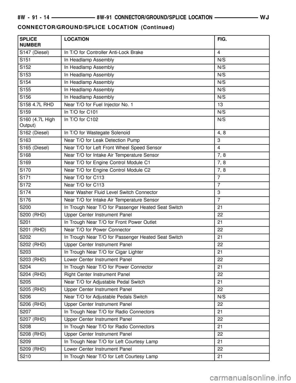
SPLICE
NUMBERLOCATION FIG.
S147 (Diesel) In T/O for Controller Anti-Lock Brake 4
S151 In Headlamp Assembly N/S
S152 In Headlamp Assembly N/S
S153 In Headlamp Assembly N/S
S154 In Headlamp Assembly N/S
S155 In Headlamp Assembly N/S
S156 In Headlamp Assembly N/S
S158 4.7L RHD Near T/O for Fuel Injector No. 1 13
S159 In T/O for C101 N/S
S160 (4.7L High
Output)In T/O for C102 N/S
S162 (Diesel) In T/O for Wastegate Solenoid 4, 8
S163 Near T/O for Leak Detection Pump 3
S165 (Diesel) Near T/O for Left Front Wheel Speed Sensor 4
S168 Near T/O for Intake Air Temperature Sensor 7, 8
S169 Near T/O for Engine Control Module C1 7, 8
S170 Near T/O for Engine Control Module C2 7, 8
S171 Near T/O for C113 7
S172 Near T/O for C113 7
S174 Near Washer Fluid Level Switch Connector 3
S176 Near T/O for Intake Air Temperature Sensor 7
S200 In Trough Near T/O for Passenger Heated Seat Switch 21
S200 (RHD) Upper Center Instrument Panel 22
S201 In Trough Near T/O for Front Power Outlet 21
S201 (RHD) Near T/O for Power Connector 22
S202 In Trough Near T/O for Passenger Heated Seat Switch 21
S202 (RHD) Upper Center Instrument Panel 22
S203 In Trough Near T/O for Cigar Lighter 21
S203 (RHD) Lower Center Instrument Panel 22
S204 In Trough Near T/O for Power Connector 21
S204 (RHD) Right Center Instrument Panel 22
S205 Near T/O for Adjustable Pedal Switch 21
S205 (RHD) Upper Center Instrument Panel 22
S206 Near T/O for Adjustable Pedals Switch N/S
S206 (RHD) Upper Center Instrument Panel 22
S207 In Trough Near T/O for Radio Connectors 21
S207 (RHD) Upper Center Instrument Panel 22
S208 In Trough Near T/O for Radio Connectors 21
S208 (RHD) Upper Center Instrument Panel 22
S209 In Trough Near T/O for Left Courtesy Lamp 21
S209 (RHD) Lower Center Instrument Panel 22
S210 In Trough Near T/O for Left Courtesy Lamp 21
8W - 91 - 14 8W-91 CONNECTOR/GROUND/SPLICE LOCATIONWJ
CONNECTOR/GROUND/SPLICE LOCATION (Continued)
Page 1245 of 2199
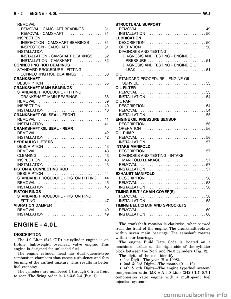
REMOVAL
REMOVAL - CAMSHAFT BEARINGS.......31
REMOVAL - CAMSHAFT................31
INSPECTION
INSPECTION - CAMSHAFT BEARINGS.....31
INSPECTION - CAMSHAFT..............31
INSTALLATION
INSTALLATION - CAMSHAFT BEARINGS . . . 32
INSTALLATION - CAMSHAFT............32
CONNECTING ROD BEARINGS
STANDARD PROCEDURE - FITTING
CONNECTING ROD BEARINGS..........33
CRANKSHAFT
DESCRIPTION.........................35
CRANKSHAFT MAIN BEARINGS
STANDARD PROCEDURE - FITTING
CRANKSHAFT MAIN BEARINGS..........36
REMOVAL.............................39
INSPECTION..........................40
INSTALLATION.........................40
CRANKSHAFT OIL SEAL - FRONT
REMOVAL.............................41
INSTALLATION.........................41
CRANKSHAFT OIL SEAL - REAR
REMOVAL.............................42
INSTALLATION.........................42
HYDRAULIC LIFTERS
DESCRIPTION.........................43
REMOVAL.............................43
CLEANING............................43
INSPECTION..........................43
INSTALLATION.........................43
PISTON & CONNECTING ROD
DESCRIPTION.........................44
STANDARD PROCEDURE - PISTON FITTING . 44
REMOVAL.............................45
INSTALLATION.........................46
PISTON RINGS
STANDARD PROCEDURE - PISTON RING
FITTING.............................47
VIBRATION DAMPER
REMOVAL.............................49
INSTALLATION.........................49STRUCTURAL SUPPORT
REMOVAL.............................49
INSTALLATION.........................50
LUBRICATION
DESCRIPTION.........................50
OPERATION...........................50
DIAGNOSIS AND TESTING
DIAGNOSIS AND TESTING - ENGINE OIL
PRESSURE..........................51
DIAGNOSIS AND TESTING - ENGINE OIL
LEAK...............................51
OIL
STANDARD PROCEDURE - ENGINE OIL
SERVICE............................53
OIL FILTER
REMOVAL.............................53
INSTALLATION.........................54
OIL PAN
DESCRIPTION.........................54
REMOVAL.............................54
INSTALLATION.........................55
ENGINE OIL PRESSURE SENSOR
DESCRIPTION.........................56
OPERATION...........................56
OIL PUMP
REMOVAL.............................56
INSTALLATION.........................57
INTAKE MANIFOLD
DESCRIPTION.........................57
DIAGNOSIS AND TESTING - INTAKE
MANIFOLD LEAKAGE..................57
REMOVAL.............................57
INSTALLATION.........................57
EXHAUST MANIFOLD
DESCRIPTION.........................58
REMOVAL.............................58
INSTALLATION.........................58
TIMING BELT / CHAIN COVER(S)
REMOVAL.............................58
INSTALLATION.........................58
TIMING BELT/CHAIN AND SPROCKETS
REMOVAL.............................60
INSTALLATION.........................60
ENGINE - 4.0L
DESCRIPTION
The 4.0 Liter (242 CID) six-cylinder engine is an
In-line, lightweight, overhead valve engine. This
engine is designed for unleaded fuel.
The engine cylinder head has dual quench-type
combustion chambers that create turbulence and fast
burning of the air/fuel mixture. This results in better
fuel economy.
The cylinders are numbered 1 through 6 from front
to rear. The firing order is 1-5-3-6-2-4 (Fig. 1).The crankshaft rotation is clockwise, when viewed
from the front of the engine. The crankshaft rotates
within seven main bearings. The camshaft rotates
within four bearings.
The engine Build Date Code is located on a
machined surface on the right side of the cylinder
block between the No.2 and No.3 cylinders (Fig. 2).
The digits of the code identify:
²1st DigitÐThe year (8 = 1998).
²2nd & 3rd DigitsÐThe month (01 - 12).
²4th & 5th DigitsÐThe engine type/fuel system/
compression ratio (MX = A 4.0 Liter (242 CID) 8.7:1
compression ratio engine with a multi-point fuel
injection system).
9 - 2 ENGINE - 4.0LWJ