2002 JEEP GRAND CHEROKEE Rear differential
[x] Cancel search: Rear differentialPage 146 of 2199

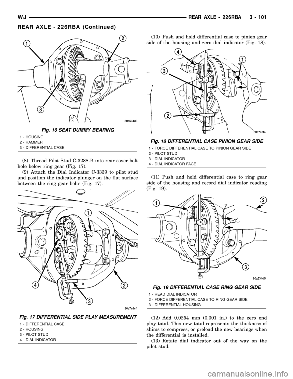
(8) Thread Pilot Stud C-3288-B into rear cover bolt
hole below ring gear (Fig. 17).
(9) Attach the Dial Indicator C-3339 to pilot stud
and position the indicator plunger on the flat surface
between the ring gear bolts (Fig. 17).(10) Push and hold differential case to pinion gear
side of the housing and zero dial indicator (Fig. 18).
(11) Push and hold differential case to ring gear
side of the housing and record dial indicator reading
(Fig. 19).
(12) Add 0.0254 mm (0.001 in.) to the zero end
play total. This new total represents the thickness of
shims to compress, or preload the new bearings when
the differential is installed.
(13) Rotate dial indicator out of the way on the
pilot stud.
Fig. 16 SEAT DUMMY BEARING
1 - HOUSING
2 - HAMMER
3 - DIFFERENTIAL CASE
Fig. 17 DIFFERENTIAL SIDE PLAY MEASUREMENT
1 - DIFFERENTIAL CASE
2 - HOUSING
3 - PILOT STUD
4 - DIAL INDICATOR
Fig. 18 DIFFERENTIAL CASE PINION GEAR SIDE
1 - FORCE DIFFERENTIAL CASE TO PINION GEAR SIDE
2 - PILOT STUD
3 - DIAL INDICATOR
4 - DIAL INDICATOR FACE
Fig. 19 DIFFERENTIAL CASE RING GEAR SIDE
1 - READ DIAL INDICATOR
2 - FORCE DIFFERENTIAL CASE TO RING GEAR SIDE
3 - DIFFERENTIAL HOUSING
WJREAR AXLE - 226RBA 3 - 101
REAR AXLE - 226RBA (Continued)
Page 147 of 2199

(14) Remove differential case and dummy bearings
from the housing.
(15) Install the pinion gear in the housing. Install
the pinion yoke and establish the correct pinion
rotating torque.
(16) Install differential case and Dummy Bearings
6929-A in the housing.
(17) Install a single dummy shim in the ring gear
side. Install bearing caps and tighten bolts snug.
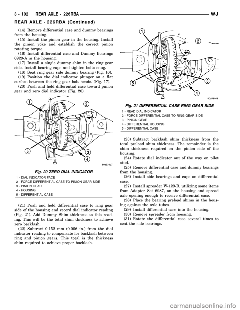
(18) Seat ring gear side dummy bearing (Fig. 16).
(19) Position the dial indicator plunger on a flat
surface between the ring gear bolt heads. (Fig. 17).
(20) Push and hold differential case toward pinion
gear and zero dial indicator (Fig. 20).
(21) Push and hold differential case to ring gear
side of the housing and record dial indicator reading
(Fig. 21). Add Dummy Shim thickness to this read-
ing. This will be the total shim thickness to achieve
zero backlash.
(22) Subtract 0.152 mm (0.006 in.) from the dial
indicator reading to compensate for backlash between
ring and pinion gears. This total is the thickness
shim required to achieve proper backlash.(23) Subtract backlash shim thickness from the
total preload shim thickness. The remainder is the
shim thickness required on the pinion side of the
housing.
(24) Rotate dial indicator out of the way on pilot
stud.
(25) Remove differential case and dummy bearings
from the housing.
(26) Install side bearings and cups on differential
case.
(27) Install spreader W-129-B, utilizing some items
from Adapter Set 6987, on the housing and spread
axle opening enough to receive differential case.
(28) Place the bearing preload shims in the hous-
ing against the axle tubes.
(29) Install differential case into the housing.
(30) Remove spreader from housing.
(31) Rotate the differential case several times to
seat the side bearings.
Fig. 20 ZERO DIAL INDICATOR
1 - DIAL INDICATOR FACE
2 - FORCE DIFFERENTIAL CASE TO PINION GEAR SIDE
3 - PINION GEAR
4 - HOUSING
5 - DIFFERENTIAL CASE
Fig. 21 DIFFERENTIAL CASE RING GEAR SIDE
1 - READ DIAL INDICATOR
2 - FORCE DIFFERENTIAL CASE TO RING GEAR SIDE
3 - PINION GEAR
4 - DIFFERENTIAL HOUSING
5 - DIFFERENTIAL CASE
3 - 102 REAR AXLE - 226RBAWJ
REAR AXLE - 226RBA (Continued)
Page 148 of 2199

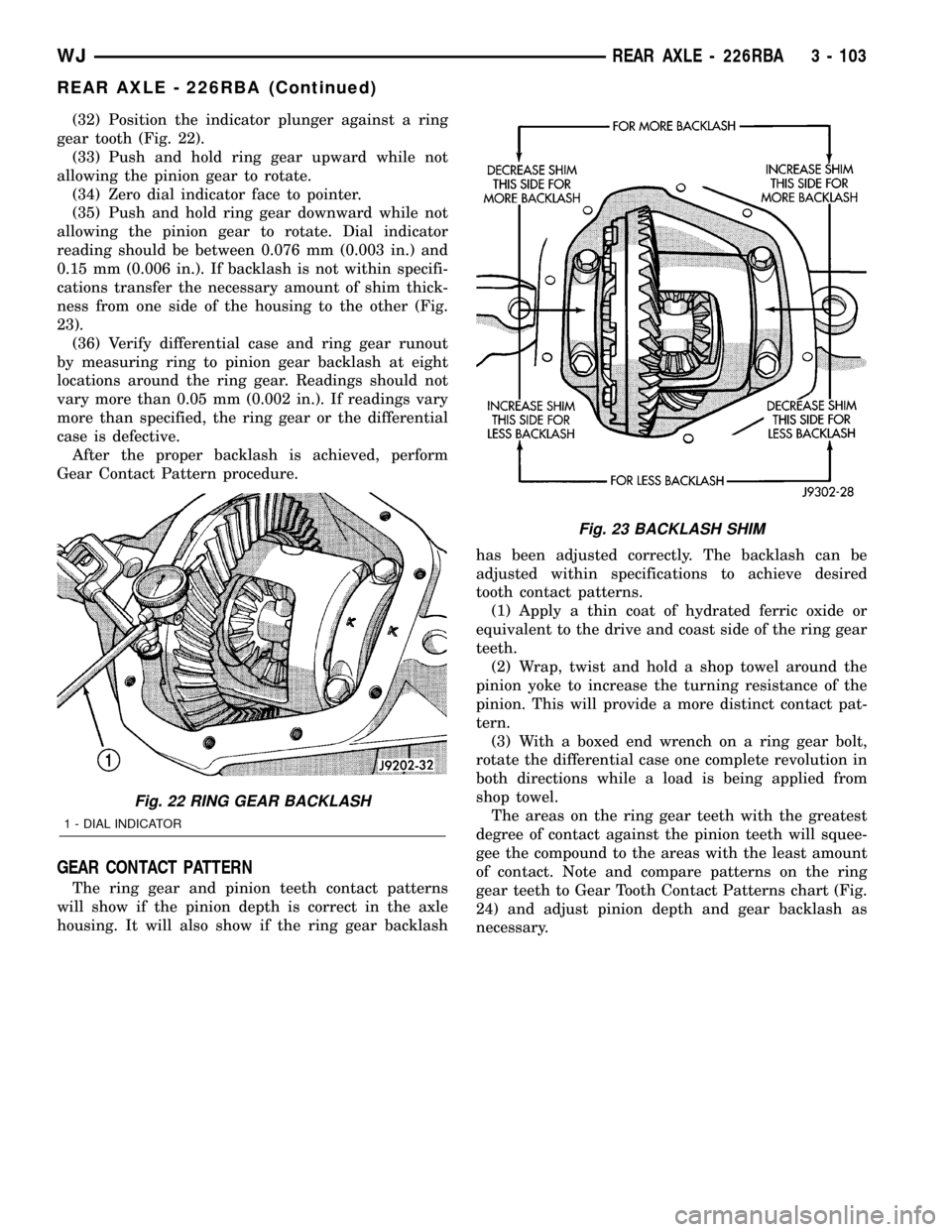
(32) Position the indicator plunger against a ring
gear tooth (Fig. 22).
(33) Push and hold ring gear upward while not
allowing the pinion gear to rotate.
(34) Zero dial indicator face to pointer.
(35) Push and hold ring gear downward while not
allowing the pinion gear to rotate. Dial indicator
reading should be between 0.076 mm (0.003 in.) and
0.15 mm (0.006 in.). If backlash is not within specifi-
cations transfer the necessary amount of shim thick-
ness from one side of the housing to the other (Fig.
23).
(36) Verify differential case and ring gear runout
by measuring ring to pinion gear backlash at eight
locations around the ring gear. Readings should not
vary more than 0.05 mm (0.002 in.). If readings vary
more than specified, the ring gear or the differential
case is defective.
After the proper backlash is achieved, perform
Gear Contact Pattern procedure.
GEAR CONTACT PATTERN
The ring gear and pinion teeth contact patterns
will show if the pinion depth is correct in the axle
housing. It will also show if the ring gear backlashhas been adjusted correctly. The backlash can be
adjusted within specifications to achieve desired
tooth contact patterns.
(1) Apply a thin coat of hydrated ferric oxide or
equivalent to the drive and coast side of the ring gear
teeth.
(2) Wrap, twist and hold a shop towel around the
pinion yoke to increase the turning resistance of the
pinion. This will provide a more distinct contact pat-
tern.
(3) With a boxed end wrench on a ring gear bolt,
rotate the differential case one complete revolution in
both directions while a load is being applied from
shop towel.
The areas on the ring gear teeth with the greatest
degree of contact against the pinion teeth will squee-
gee the compound to the areas with the least amount
of contact. Note and compare patterns on the ring
gear teeth to Gear Tooth Contact Patterns chart (Fig.
24) and adjust pinion depth and gear backlash as
necessary.
Fig. 22 RING GEAR BACKLASH
1 - DIAL INDICATOR
Fig. 23 BACKLASH SHIM
WJREAR AXLE - 226RBA 3 - 103
REAR AXLE - 226RBA (Continued)
Page 150 of 2199

DIFFERENTIAL BEARING PRELOAD CHECK
The final check on the differential assembly before
installing the axles is torque to rotate pinion and dif-
ferential combined. This will verify the correct differ-
ential bearing preload.Torque to rotate the differential and pinion should
be the torque to rotate the pinion plus 0.79-1.24 N´m
(7-11 in. lbs.).
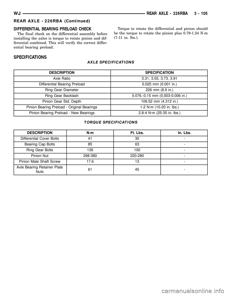
SPECIFICATIONS
AXLE SPECIFICATIONS
DESCRIPTION SPECIFICATION
Axle Ratio 3.31, 3.55, 3.73, 3.91
Differential Bearing Preload 0.025 mm (0.001 in.)
Ring Gear Diameter 226 mm (8.9 in.)
Ring Gear Backlash 0.076.-0.15 mm (0.003-0.006 in.)
Pinion Gear Std. Depth 109.52 mm (4.312 in.)
Pinion Bearing Preload - Original Bearings 1-2 N´m (10-20 in. lbs.)
Pinion Bearing Preload - New Bearings 2.8-4 N´m (25-35 in. lbs.)
TORQUE SPECIFICATIONS
DESCRIPTION N´m Ft. Lbs. In. Lbs.
Differential Cover Bolts 41 30 -
Bearing Cap Bolts 85 63 -
Ring Gear Bolts 136 100 -
Pinion Nut 298-380 220-280 -
Pinion Mate Shaft Screw 17.6 13 -
Axle Bearing Retainer Plate
Nuts61 45 -
WJREAR AXLE - 226RBA 3 - 105
REAR AXLE - 226RBA (Continued)
Page 154 of 2199

AXLE SHAFTS
REMOVAL
(1) Place transmission in neutral.
(2) Raise and support vehicle.
(3) Remove wheel and tire assembly.
(4) Remove brake caliper and rotor.
(5) Remove nuts holding axle retainer plate to axle
tube from the rear of the axle flange.
(6) Pull axle shaft from the axle with Slide Ham-
mer 7420 and Adapter 6790. Mount the adapter to
the axle with lug nuts.
NOTE: The axle bearing race is normally loose in
the axle tube.
INSTALLATION
(1) Insall axle into the axle tube with the flat area
of the retainer plate upward.
(2) Insert retaining plate studs into the brake
backing plate and axle tube flange.
(3) Install retainer nuts and tighten nuts to 61
N´m (45 ft. lbs.).
(4) Install the brake rotor and caliper.
(5) Install wheel and tire.
(6) Check and fill the differential with gear lubri-
cant.
(7) Lower vehicle.
AXLE BEARINGS/SEALS
REMOVAL
(1) Remove axle shaft from vehicle.
NOTE: The axle bearing race is normally loose in
the axle tube.
(2) Drill a shallow hole into soft steel axle bearing
retaining ring with a 3/8 in. drill bit (Fig. 25). Use a
drill depth stop to avoid marking the axle.
(3) With a cold chisel cut the retaining ring across
drilled hole. (Fig. 26)
(4) Slide retaining ring from axle shaft.
Fig. 25 DRILL RETAINING RING
1 - DRILL BIT
2 - AXLE
3 - RETAINING PLATE
4 - RETAINING RING
Fig. 26 RETAINING RING
1 - AXLE
2 - COLD CHISEL
3 - VISE
4 - RETAINING RING
WJREAR AXLE - 226RBA 3 - 109
Page 157 of 2199

(10) Remove pinion seal with Remover 7794-A and
a slide hammer (Fig. 33).
INSTALLATION
(1) Apply a light coating of gear lubricant on the
lip of pinion seal. Install seal with an appropriate in
installer (Fig. 34).
(2) Install yoke on the pinion gear with Installer
C-3718 and Spanner Wrench 6958 (Fig. 35).
(3) Install anewnut on the pinion gear.Tighten
the nut only enough to remove the shaft end
play.
CAUTION: Do not exceed the minimum tightening
torque 298 N´m (220 ft. lbs.) when installing the pin-
ion yoke retaining nut at this point. Damage to col-
lapsible spacer or bearings may result.(4) Rotate the pinion a minimum of ten times and
verify pinion rotates smoothly. Rotate the pinion
shaft using an inch pound torque wrench. Rotating
torque should be equal to the reading recorded dur-
ing removal, plus 0.56 N´m (5 in. lbs.) (Fig. 36).
Fig. 33 Pinion Seal Remover
1 - REMOVER
2 - SLIDE HAMMER
3 - PINION SEAL
Fig. 34 PINION SEAL INSTALLER
1 - HANDLE
2 - INSTALLER
Fig. 35 PINION YOKE INSTALLER
1 - INSTALLER
2 - PINION YOKE
3 - DIFFERENTIAL HOUSING
4 - SPANNER WRENCH
Fig. 36 PINION ROTATING TORQUE
1 - TORQUE WRENCH
2 - PINION YOKE
3 - 112 REAR AXLE - 226RBAWJ
PINION SEAL (Continued)
Page 158 of 2199

(5) If rotating torque is low, use Wrench 6958 to
hold the pinion yoke (Fig. 37) and tighten the pinion
shaft nut in 6.8 N´m (5 ft. lbs.) increments until
rotating torque is achieved.
CAUTION: If the maximum tightening torque is
reached prior to reaching the required rotating
torque, the collapsible spacer may have been dam-
aged. Replace the collapsible spacer.
(6) Install propeller shaft with reference marks
aligned.
(7) Fill differential with gear lubricant.
(8) Install the brake rotors and calipers.
(9) Install wheel and tire assemblies.
(10) Lower the vehicle.
COLLAPSIBLE SPACER
REMOVAL
(1) Raise and support the vehicle.
(2) Remove wheel and tire assemblies.
(3) Remove rear brake calipers and rotors.
(4) Mark propeller shaft and pinion yoke for
installation reference and remove propeller shaft.
(5) Rotate pinion gear a minimum of ten times and
verify pinion rotates smoothly.
(6) Record rotate torque of the pinion gear, with an
inch pound torque wrench.
(7) Hold pinion yoke with Spanner Wrench 6958
and remove pinion nut and washer (Fig. 38).
(8) Remove pinion yoke with Remover C-452 and
Wrench C-3281 (Fig. 39).
Fig. 37 PINION SHAFT NUT
1 - SPANNER WRENCH
2 - PIPE
3 - TORQUE WRENCH
Fig. 38 PINION YOKE HOLDER
1 - 1 in. PIPE
2 - PINION YOKE
3 - SPANNER WRENCH
4 - LOWER CONTROL ARM
Fig. 39 PINION YOKE PULLER
1 - WRENCH
2 - PINION YOKE
3 - PULLER
WJREAR AXLE - 226RBA 3 - 113
PINION SEAL (Continued)
Page 159 of 2199

(9) Remove pinion shaft seal with Remover 7794-A
and slide hammer (Fig. 40).
(10)
Remove front pinion bearing using a pair of pick
tools to pull the bearing off the pinion gear shaft.
NOTE: If the pinion bearing becomes bound on the
pinion shaft, lightly tap the end of the shaft with a
rawhide/rubber mallet.
(11) Remove the collapsible spacer.
INSTALLATION
(1) Install anewcollapsible spacer on pinion
shaft.
(2) Install pinion front bearing on the pinion shaft.
(3) Apply a light coating of gear lubricant on the
lip of pinion seal and install seal with an appropriate
installer (Fig. 41).
(4) Install yoke with Installer C-3718 and Spanner
Wrench 6958 (Fig. 42).(5) Install yoke washer andnewnut on the pinion
gear. Tighten the nut to 271 N´m (200 ft. lbs.).
CAUTION: Never loosen pinion gear nut to decrease
pinion rotating torque and never exceed specified pre-
load torque. If preload torque or rotating torque is
exceeded a new collapsible spacer must be installed.
(6) Using yoke with Spanner Wrench 6958 and a
torque wrench set at 380 N´m (280 ft. lbs.), (Fig. 43)
slowly tighten the nut in 6.8 N´m (5 ft. lbs.) incre-
ments until the rotating torque is achieved. Measure
the rotating torque frequently to avoid over crushing
the collapsible spacer (Fig. 44).
Fig. 43 PINION NUT
1 - SPANNER WRENCH
2 - PIPE
3 - TORQUE WRENCH
Fig. 40 PINION SEAL REMOVER
1 - REMOVER
2 - SLIDE HAMMER
3 - PINION SEAL
Fig. 41 PINION SEAL INSTALLER
1 - HANDLE
2 - INSTALLER
Fig. 42 Pinion Yoke Installer
1 - INSTALLER
2 - PINION YOKE
3 - DIFFERENTIAL HOUSING
4 - SPANNER WRENCH
3 - 114 REAR AXLE - 226RBAWJ
COLLAPSIBLE SPACER (Continued)