2002 JEEP GRAND CHEROKEE Engine coolant sensor
[x] Cancel search: Engine coolant sensorPage 1542 of 2199
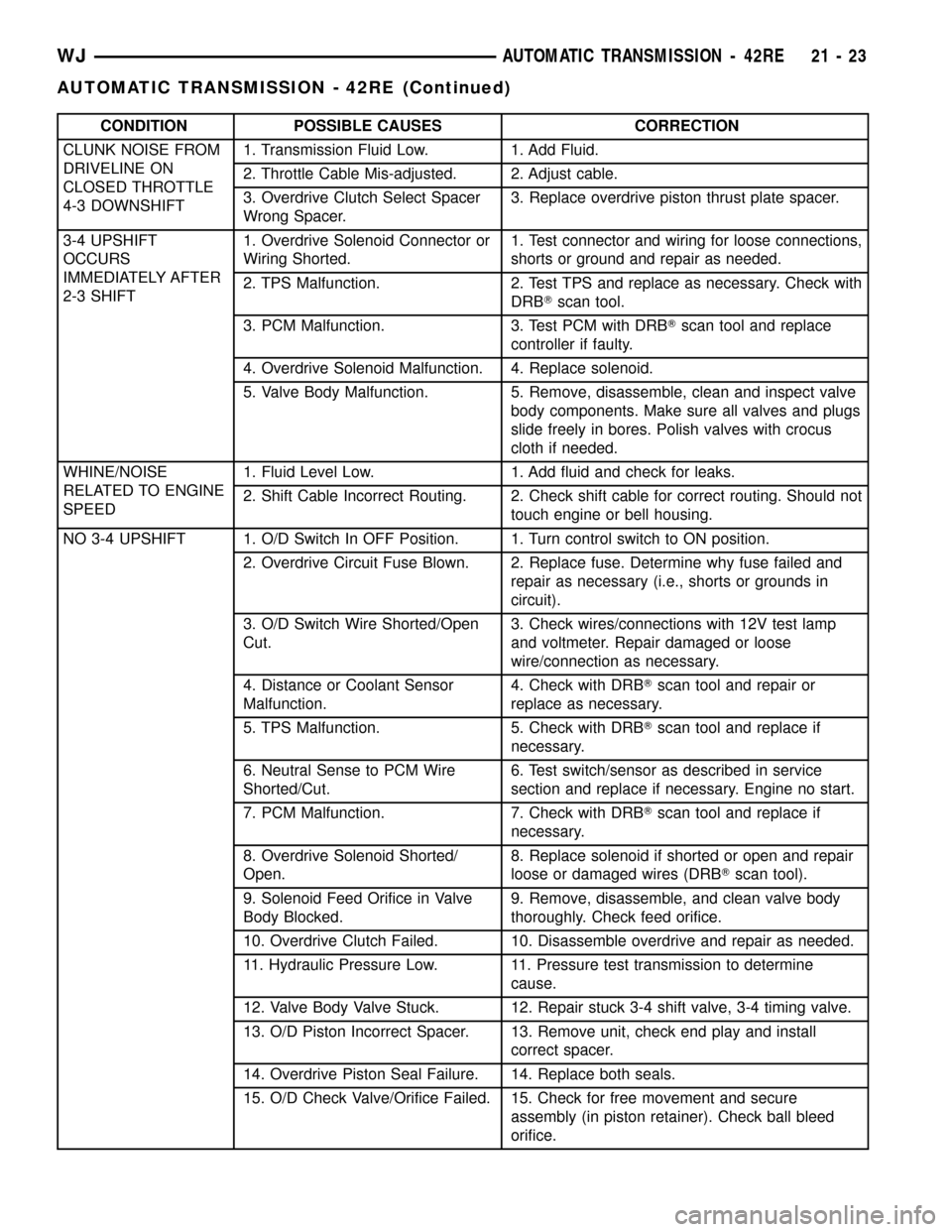
CONDITION POSSIBLE CAUSES CORRECTION
CLUNK NOISE FROM
DRIVELINE ON
CLOSED THROTTLE
4-3 DOWNSHIFT1. Transmission Fluid Low. 1. Add Fluid.
2. Throttle Cable Mis-adjusted. 2. Adjust cable.
3. Overdrive Clutch Select Spacer
Wrong Spacer.3. Replace overdrive piston thrust plate spacer.
3-4 UPSHIFT
OCCURS
IMMEDIATELY AFTER
2-3 SHIFT1. Overdrive Solenoid Connector or
Wiring Shorted.1.
Test connector and wiring for loose connections,
shorts or ground and repair as needed.
2. TPS Malfunction. 2. Test TPS and replace as necessary. Check with
DRBTscan tool.
3. PCM Malfunction. 3. Test PCM with DRBTscan tool and replace
controller if faulty.
4. Overdrive Solenoid Malfunction. 4. Replace solenoid.
5. Valve Body Malfunction. 5. Remove, disassemble, clean and inspect valve
body components. Make sure all valves and plugs
slide freely in bores. Polish valves with crocus
cloth if needed.
WHINE/NOISE
RELATED TO ENGINE
SPEED1. Fluid Level Low. 1. Add fluid and check for leaks.
2. Shift Cable Incorrect Routing. 2. Check shift cable for correct routing. Should not
touch engine or bell housing.
NO 3-4 UPSHIFT 1. O/D Switch In OFF Position. 1. Turn control switch to ON position.
2. Overdrive Circuit Fuse Blown. 2. Replace fuse. Determine why fuse failed and
repair as necessary (i.e., shorts or grounds in
circuit).
3. O/D Switch Wire Shorted/Open
Cut.3. Check wires/connections with 12V test lamp
and voltmeter. Repair damaged or loose
wire/connection as necessary.
4. Distance or Coolant Sensor
Malfunction.4. Check with DRBTscan tool and repair or
replace as necessary.
5. TPS Malfunction. 5. Check with DRBTscan tool and replace if
necessary.
6. Neutral Sense to PCM Wire
Shorted/Cut.6. Test switch/sensor as described in service
section and replace if necessary. Engine no start.
7. PCM Malfunction. 7. Check with DRBTscan tool and replace if
necessary.
8. Overdrive Solenoid Shorted/
Open.8. Replace solenoid if shorted or open and repair
loose or damaged wires (DRBTscan tool).
9. Solenoid Feed Orifice in Valve
Body Blocked.9. Remove, disassemble, and clean valve body
thoroughly. Check feed orifice.
10. Overdrive Clutch Failed. 10. Disassemble overdrive and repair as needed.
11. Hydraulic Pressure Low. 11. Pressure test transmission to determine
cause.
12. Valve Body Valve Stuck. 12. Repair stuck 3-4 shift valve, 3-4 timing valve.
13. O/D Piston Incorrect Spacer. 13. Remove unit, check end play and install
correct spacer.
14. Overdrive Piston Seal Failure. 14. Replace both seals.
15. O/D Check Valve/Orifice Failed. 15. Check for free movement and secure
assembly (in piston retainer). Check ball bleed
orifice.
WJAUTOMATIC TRANSMISSION - 42RE 21 - 23
AUTOMATIC TRANSMISSION - 42RE (Continued)
Page 1791 of 2199

REMOVAL
(1) Remove the valve body from the transmission
(Fig. 119).
(2) Remove the screws holding the transmission
solenoid/TRS assembly onto the valve body (Fig. 120).
(3) Separate the transmission solenoid/TRS assem-
bly from the valve body.
INSTALLATION
(1) Place TRS selector plate in the PARK position.
(2) Position the transmission solenoid/TRS assem-
bly onto the valve body. Be sure that both alignment
dowels are fully seated in the valve body and that
the TRS switch contacts are properly positioned in
the selector plate
(3) Install the screws to hold the transmission
solenoid/TRS assembly onto the valve body.
(4) Tighten the solenoid assembly screws adjacent
to the arrows cast into the bottom of the valve body
first. Tighten the screws to 5.7 N´m (50 in.lbs.).
(5) Tighten the remainder of the solenoid assembly
screws to 5.7 N´m (50 in.lbs.).
(6) Install the valve body into the transmission.
TRANSMISSION
TEMPERATURE SENSOR
DESCRIPTION
The transmission temperature sensor is a ther-
mistor that is integral to the Transmission Range
Sensor (TRS).
OPERATION
The transmission temperature sensor is used by
the TCM to sense the temperature of the fluid in the
sump. Since fluid temperature can affect transmis-
sion shift quality and convertor lock up, the TCM
requires this information to determine which shift
schedule to operate in.
Calculated Temperature
A failure in the temperature sensor or circuit will
result in calculated temperature being substituted for
actual temperature. Calculated temperature is a pre-
dicted fluid temperature which is calculated from a
combination of inputs:
²Battery (ambient) temperature
²Engine coolant temperature
²In-gear run time since start-up
Fig. 119 Valve Body Bolts
1 - VALVE BODY TO CASE BOLT (6)
Fig. 120 Ttransmission Solenoid/TRS Assembly
Screws
1 - SOLENOID PACK BOLTS (15)
21 - 272 AUTOMATIC TRANSMISSION - 545RFEWJ
TRANSMISSION SOLENOID/TRS ASSEMBLY (Continued)
Page 2097 of 2199
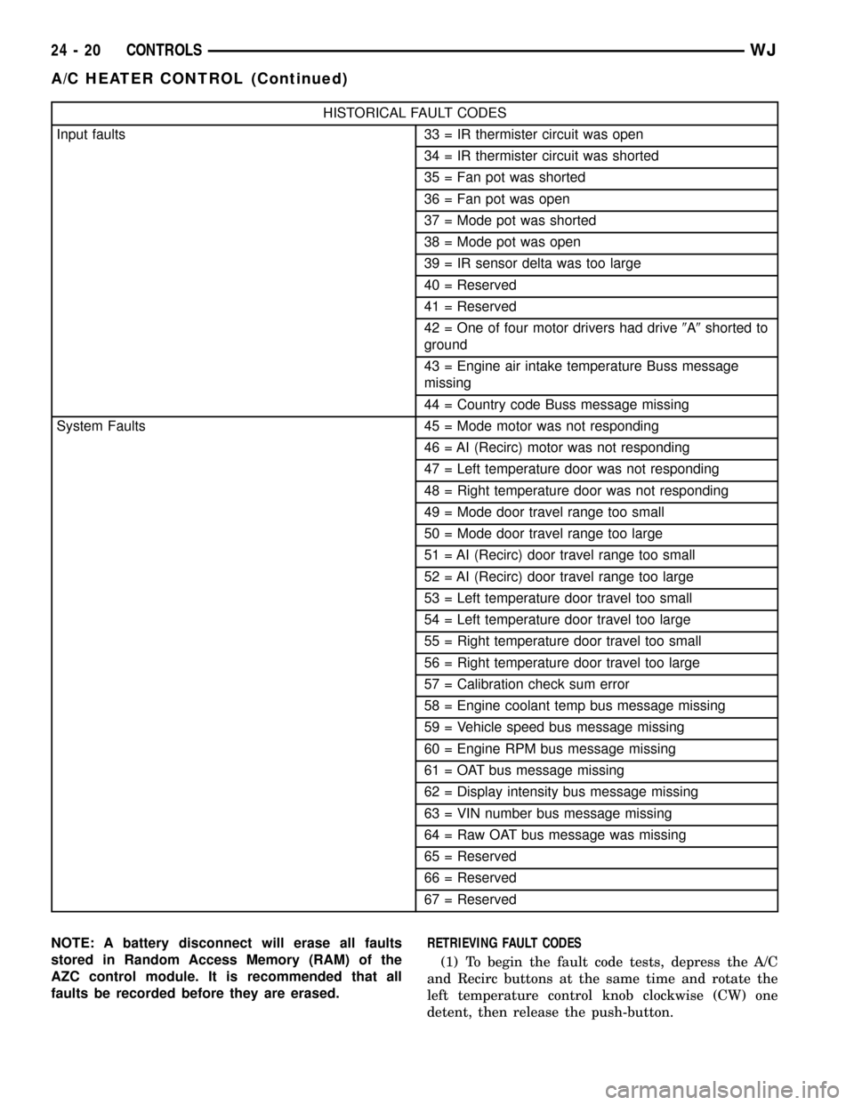
HISTORICAL FAULT CODES
Input faults 33 = IR thermister circuit was open
34 = IR thermister circuit was shorted
35 = Fan pot was shorted
36 = Fan pot was open
37 = Mode pot was shorted
38 = Mode pot was open
39 = IR sensor delta was too large
40 = Reserved
41 = Reserved
42 = One of four motor drivers had drive9A9shorted to
ground
43 = Engine air intake temperature Buss message
missing
44 = Country code Buss message missing
System Faults 45 = Mode motor was not responding
46 = AI (Recirc) motor was not responding
47 = Left temperature door was not responding
48 = Right temperature door was not responding
49 = Mode door travel range too small
50 = Mode door travel range too large
51 = AI (Recirc) door travel range too small
52 = AI (Recirc) door travel range too large
53 = Left temperature door travel too small
54 = Left temperature door travel too large
55 = Right temperature door travel too small
56 = Right temperature door travel too large
57 = Calibration check sum error
58 = Engine coolant temp bus message missing
59 = Vehicle speed bus message missing
60 = Engine RPM bus message missing
61 = OAT bus message missing
62 = Display intensity bus message missing
63 = VIN number bus message missing
64 = Raw OAT bus message was missing
65 = Reserved
66 = Reserved
67 = Reserved
NOTE: A battery disconnect will erase all faults
stored in Random Access Memory (RAM) of the
AZC control module. It is recommended that all
faults be recorded before they are erased.RETRIEVING FAULT CODES
(1) To begin the fault code tests, depress the A/C
and Recirc buttons at the same time and rotate the
left temperature control knob clockwise (CW) one
detent, then release the push-button.
24 - 20 CONTROLSWJ
A/C HEATER CONTROL (Continued)
Page 2101 of 2199
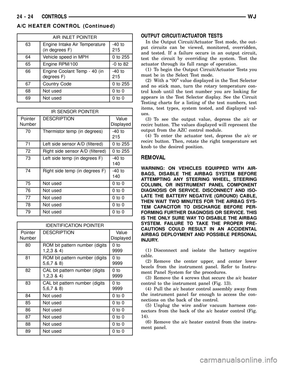
AIR INLET POINTER
63 Engine Intake Air Temperature
(in degrees F)-40 to
215
64 Vehicle speed in MPH 0 to 255
65 Engine RPM/100 -0 to 82
66 Engine Coolant Temp - 40 (in
degrees F)-40 to
215
67 Country Code 0 to 255
68 Not used 0 to 0
69 Not used 0 to 0
IR SENSOR POINTER
Pointer
NumberDESCRIPTION Value
Displayed
70 Thermistor temp (in degrees) -40 to
215
71 Left side sensor A/D (filtered) 0 to 255
72 Right side sensor A/D (filtered) 0 to 255
73 Left side temp (in degrees F) -40 to
140
74 Right side temp (in degrees F) -40 to
140
75 Not used 0 to 0
76 Not used 0 to 0
77 Not used 0 to 0
78 Not used 0 to 0
79 Not used 0 to 0
IDENTIFICATION POINTER
Pointer
NumberDESCRIPTION Value
Displayed
80 ROM bit pattern number (digits
1,2,3 & 4)0to
9999
81 ROM bit pattern number (digits
5,6,7 & 8)0to
9999
82 CAL bit pattern number (digits
1,2,3 & 4)0to
9999
83 CAL bit pattern number (digits
5,6,7 & 8)0to
9999
84 Not used 0 to 0
85 Not used 0 to 0
86 Not used 0 to 0
87 Not used 0 to 0
88 Not used 0 to 0
89 Not used 0 to 0
OUTPUT CIRCUIT/ACTUATOR TESTS
In the Output Circuit/Actuator Test mode, the out-
put circuits can be viewed, monitored, overridden,
and tested. If a failure occurs in an output circuit,
test the circuit by overriding the system. Test the
actuator through its full range of operation.
(1) To begin the Output Circuit/Actuator Tests you
must be in the Select Test mode.
(2) With a ª00º value displayed in the Test Selector
and no stick man, turn the rotary temperature con-
trol knob until the test number you are looking for
appears in the Test Selector display. See the Circuit
Testing charts for a listing of the test numbers, test
items, test types, system tested, and displayed val-
ues.
(3) To see the output value, depress the a/c or
recirc button. The values displayed will represent the
output from the AZC control module.
(4) To enter the actuator test, depress the a/c or
recirc button. Then, rotate the right temperature set
knob to the desired position.
REMOVAL
WARNING: ON VEHICLES EQUIPPED WITH AIR-
BAGS, DISABLE THE AIRBAG SYSTEM BEFORE
ATTEMPTING ANY STEERING WHEEL, STEERING
COLUMN, OR INSTRUMENT PANEL COMPONENT
DIAGNOSIS OR SERVICE. DISCONNECT AND ISO-
LATE THE BATTERY NEGATIVE (GROUND) CABLE,
THEN WAIT TWO MINUTES FOR THE AIRBAG SYS-
TEM CAPACITOR TO DISCHARGE BEFORE PER-
FORMING FURTHER DIAGNOSIS OR SERVICE. THIS
IS THE ONLY SURE WAY TO DISABLE THE AIRBAG
SYSTEM. FAILURE TO TAKE THE PROPER PRE-
CAUTIONS COULD RESULT IN AN ACCIDENTAL
AIRBAG DEPLOYMENT AND POSSIBLE PERSONAL
INJURY.
(1) Disconnect and isolate the battery negative
cable.
(2) Remove the center upper, and center lower
bezels from the instrument panel. Refer to Instru-
ment Panel System for the procedures.
(3) Remove the 4 screws that secure the a/c heater
control to the instrument panel (Fig. 13).
(4) Pull the a/c heater control assembly away from
the instrument panel far enough to access the con-
nections on the back of the control.
(5) Unplug the wire and/or vacuum harness con-
nectors from the back of the a/c heater control (Fig.
14).
(6) Remove the a/c heater control from the instru-
ment panel.
24 - 24 CONTROLSWJ
A/C HEATER CONTROL (Continued)
Page 2158 of 2199
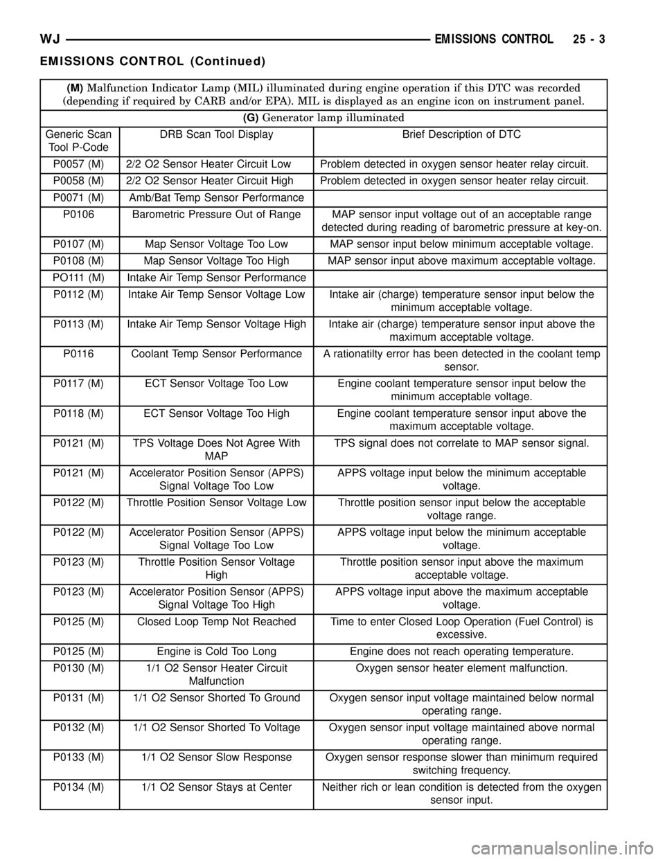
(M)Malfunction Indicator Lamp (MIL) illuminated during engine operation if this DTC was recorded
(depending if required by CARB and/or EPA). MIL is displayed as an engine icon on instrument panel.
(G)Generator lamp illuminated
Generic Scan
Tool P-CodeDRB Scan Tool Display Brief Description of DTC
P0057 (M) 2/2 O2 Sensor Heater Circuit Low Problem detected in oxygen sensor heater relay circuit.
P0058 (M) 2/2 O2 Sensor Heater Circuit High Problem detected in oxygen sensor heater relay circuit.
P0071 (M) Amb/Bat Temp Sensor Performance
P0106 Barometric Pressure Out of Range MAP sensor input voltage out of an acceptable range
detected during reading of barometric pressure at key-on.
P0107 (M) Map Sensor Voltage Too Low MAP sensor input below minimum acceptable voltage.
P0108 (M) Map Sensor Voltage Too High MAP sensor input above maximum acceptable voltage.
PO111 (M) Intake Air Temp Sensor Performance
P0112 (M) Intake Air Temp Sensor Voltage Low Intake air (charge) temperature sensor input below the
minimum acceptable voltage.
P0113 (M) Intake Air Temp Sensor Voltage High Intake air (charge) temperature sensor input above the
maximum acceptable voltage.
P0116 Coolant Temp Sensor Performance A rationatilty error has been detected in the coolant temp
sensor.
P0117 (M) ECT Sensor Voltage Too Low Engine coolant temperature sensor input below the
minimum acceptable voltage.
P0118 (M) ECT Sensor Voltage Too High Engine coolant temperature sensor input above the
maximum acceptable voltage.
P0121 (M) TPS Voltage Does Not Agree With
MAPTPS signal does not correlate to MAP sensor signal.
P0121 (M) Accelerator Position Sensor (APPS)
Signal Voltage Too LowAPPS voltage input below the minimum acceptable
voltage.
P0122 (M) Throttle Position Sensor Voltage Low Throttle position sensor input below the acceptable
voltage range.
P0122 (M) Accelerator Position Sensor (APPS)
Signal Voltage Too LowAPPS voltage input below the minimum acceptable
voltage.
P0123 (M) Throttle Position Sensor Voltage
HighThrottle position sensor input above the maximum
acceptable voltage.
P0123 (M) Accelerator Position Sensor (APPS)
Signal Voltage Too HighAPPS voltage input above the maximum acceptable
voltage.
P0125 (M) Closed Loop Temp Not Reached Time to enter Closed Loop Operation (Fuel Control) is
excessive.
P0125 (M) Engine is Cold Too Long Engine does not reach operating temperature.
P0130 (M) 1/1 O2 Sensor Heater Circuit
MalfunctionOxygen sensor heater element malfunction.
P0131 (M) 1/1 O2 Sensor Shorted To Ground Oxygen sensor input voltage maintained below normal
operating range.
P0132 (M) 1/1 O2 Sensor Shorted To Voltage Oxygen sensor input voltage maintained above normal
operating range.
P0133 (M) 1/1 O2 Sensor Slow Response Oxygen sensor response slower than minimum required
switching frequency.
P0134 (M) 1/1 O2 Sensor Stays at Center Neither rich or lean condition is detected from the oxygen
sensor input.
WJEMISSIONS CONTROL 25 - 3
EMISSIONS CONTROL (Continued)
Page 2166 of 2199
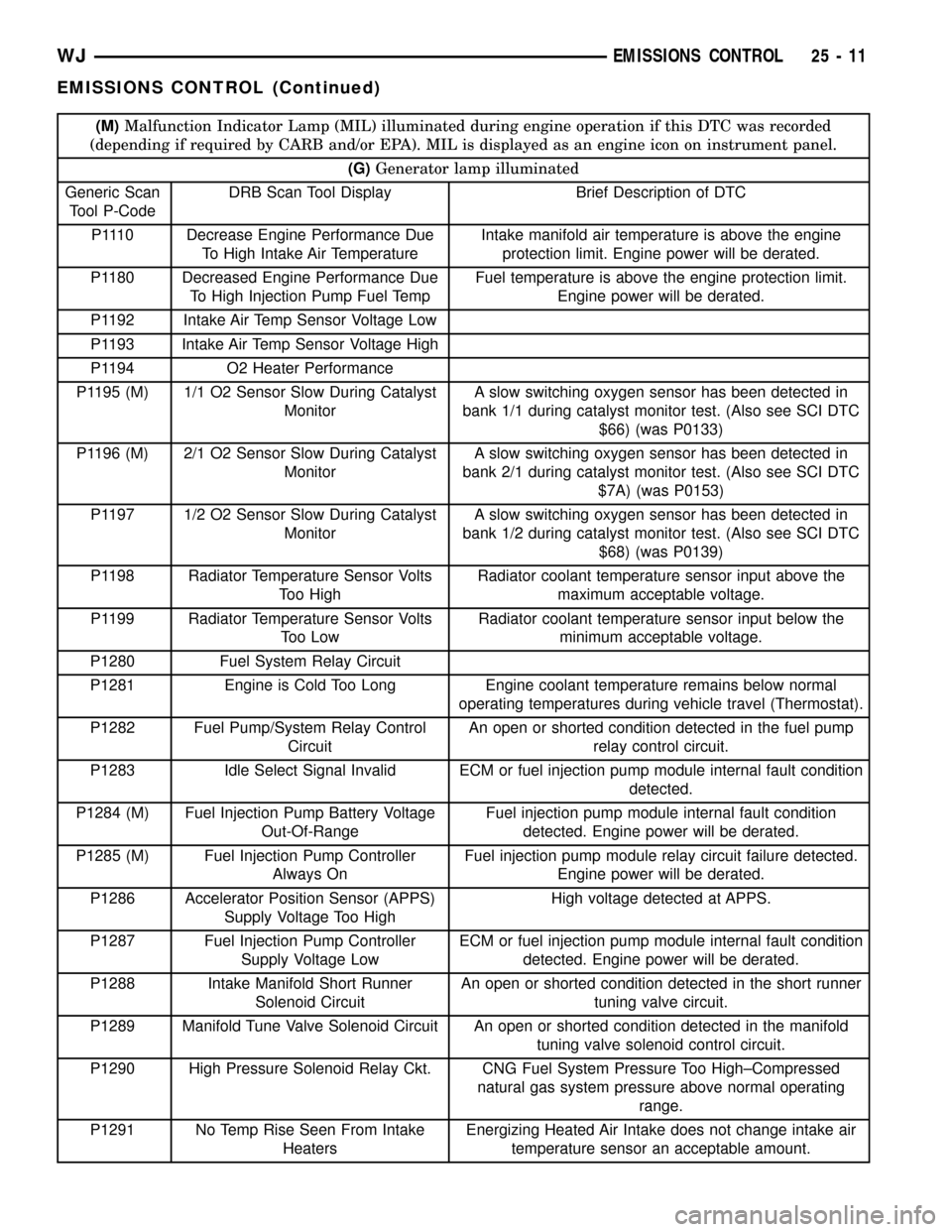
(M)Malfunction Indicator Lamp (MIL) illuminated during engine operation if this DTC was recorded
(depending if required by CARB and/or EPA). MIL is displayed as an engine icon on instrument panel.
(G)Generator lamp illuminated
Generic Scan
Tool P-CodeDRB Scan Tool Display Brief Description of DTC
P1110 Decrease Engine Performance Due
To High Intake Air TemperatureIntake manifold air temperature is above the engine
protection limit. Engine power will be derated.
P1180 Decreased Engine Performance Due
To High Injection Pump Fuel TempFuel temperature is above the engine protection limit.
Engine power will be derated.
P1192 Intake Air Temp Sensor Voltage Low
P1193 Intake Air Temp Sensor Voltage High
P1194 O2 Heater Performance
P1195 (M) 1/1 O2 Sensor Slow During Catalyst
MonitorA slow switching oxygen sensor has been detected in
bank 1/1 during catalyst monitor test. (Also see SCI DTC
$66) (was P0133)
P1196 (M) 2/1 O2 Sensor Slow During Catalyst
MonitorA slow switching oxygen sensor has been detected in
bank 2/1 during catalyst monitor test. (Also see SCI DTC
$7A) (was P0153)
P1197 1/2 O2 Sensor Slow During Catalyst
MonitorA slow switching oxygen sensor has been detected in
bank 1/2 during catalyst monitor test. (Also see SCI DTC
$68) (was P0139)
P1198 Radiator Temperature Sensor Volts
Too HighRadiator coolant temperature sensor input above the
maximum acceptable voltage.
P1199 Radiator Temperature Sensor Volts
Too LowRadiator coolant temperature sensor input below the
minimum acceptable voltage.
P1280 Fuel System Relay Circuit
P1281 Engine is Cold Too Long Engine coolant temperature remains below normal
operating temperatures during vehicle travel (Thermostat).
P1282 Fuel Pump/System Relay Control
CircuitAn open or shorted condition detected in the fuel pump
relay control circuit.
P1283 Idle Select Signal Invalid ECM or fuel injection pump module internal fault condition
detected.
P1284 (M) Fuel Injection Pump Battery Voltage
Out-Of-RangeFuel injection pump module internal fault condition
detected. Engine power will be derated.
P1285 (M) Fuel Injection Pump Controller
Always OnFuel injection pump module relay circuit failure detected.
Engine power will be derated.
P1286 Accelerator Position Sensor (APPS)
Supply Voltage Too HighHigh voltage detected at APPS.
P1287 Fuel Injection Pump Controller
Supply Voltage LowECM or fuel injection pump module internal fault condition
detected. Engine power will be derated.
P1288 Intake Manifold Short Runner
Solenoid CircuitAn open or shorted condition detected in the short runner
tuning valve circuit.
P1289 Manifold Tune Valve Solenoid Circuit An open or shorted condition detected in the manifold
tuning valve solenoid control circuit.
P1290 High Pressure Solenoid Relay Ckt. CNG Fuel System Pressure Too High±Compressed
natural gas system pressure above normal operating
range.
P1291 No Temp Rise Seen From Intake
HeatersEnergizing Heated Air Intake does not change intake air
temperature sensor an acceptable amount.
WJEMISSIONS CONTROL 25 - 11
EMISSIONS CONTROL (Continued)
Page 2174 of 2199

and deteriorate engine performance, driveability and
fuel economy.
The catalyst monitor uses dual oxygen sensors
(O2S's) to monitor the efficiency of the converter. The
dual O2S's sensor strategy is based on the fact that
as a catalyst deteriorates, its oxygen storage capacity
and its efficiency are both reduced. By monitoring
the oxygen storage capacity of a catalyst, its effi-
ciency can be indirectly calculated. The upstream
O2S is used to detect the amount of oxygen in the
exhaust gas before the gas enters the catalytic con-
verter. The PCM calculates the A/F mixture from the
output of the O2S. A low voltage indicates high oxy-
gen content (lean mixture). A high voltage indicates a
low content of oxygen (rich mixture).
When the upstream O2S detects a lean condition,
there is an abundance of oxygen in the exhaust gas.
A functioning converter would store this oxygen so it
can use it for the oxidation of HC and CO. As the
converter absorbs the oxygen, there will be a lack of
oxygen downstream of the converter. The output of
the downstream O2S will indicate limited activity in
this condition.
As the converter loses the ability to store oxygen,
the condition can be detected from the behavior of
the downstream O2S. When the efficiency drops, no
chemical reaction takes place. This means the con-
centration of oxygen will be the same downstream as
upstream. The output voltage of the downstream
O2S copies the voltage of the upstream sensor. The
only difference is a time lag (seen by the PCM)
between the switching of the O2S's.
To monitor the system, the number of lean-to-rich
switches of upstream and downstream O2S's is
counted. The ratio of downstream switches to
upstream switches is used to determine whether the
catalyst is operating properly. An effective catalyst
will have fewer downstream switches than it has
upstream switches i.e., a ratio closer to zero. For a
totally ineffective catalyst, this ratio will be one-to-
one, indicating that no oxidation occurs in the device.
The system must be monitored so that when cata-
lyst efficiency deteriorates and exhaust emissions
increase to over the legal limit, the MIL will be illu-
minated.
DESCRIPTION - TRIP DEFINITION
The term ªTripº has different meanings depending
on what the circumstances are. If the MIL (Malfunc-
tion Indicator Lamp) is OFF, a Trip is defined as
when the Oxygen Sensor Monitor and the Catalyst
Monitor have been completed in the same drive cycle.
When any Emission DTC is set, the MIL on the
dash is turned ON. When the MIL is ON, it takes 3
good trips to turn the MIL OFF. In this case, itdepends on what type of DTC is set to know what a
ªTripº is.
For the Fuel Monitor or Mis-Fire Monitor (contin-
uous monitor), the vehicle must be operated in the
ªSimilar Condition Windowº for a specified amount of
time to be considered a Good Trip.
If a Non-Contiuous OBDII Monitor fails twice in a
row and turns ON the MIL, re-running that monitor
which previously failed, on the next start-up and
passing the monitor, is considered to be a Good Trip.
These will include the following:
²Oxygen Sensor
²Catalyst Monitor
²Purge Flow Monitor
²Leak Detection Pump Monitor (if equipped)
²EGR Monitor (if equipped)
²Oxygen Sensor Heater Monitor
If any other Emission DTC is set (not an OBDII
Monitor), a Good Trip is considered to be when the
Oxygen Sensor Monitor and Catalyst Monitor have
been completed; or 2 Minutes of engine run time if
the Oxygen Sensor Monitor or Catalyst Monitor have
been stopped from running.
It can take up to 2 Failures in a row to turn on the
MIL. After the MIL is ON, it takes 3 Good Trips to
turn the MIL OFF. After the MIL is OFF, the PCM
will self-erase the DTC after 40 Warm-up cycles. A
Warm-up cycle is counted when the ECT (Engine
Coolant Temperature Sensor) has crossed 160ÉF and
has risen by at least 40ÉF since the engine has been
started.
DESCRIPTION - COMPONENT MONITORS
There are several components that will affect vehi-
cle emissions if they malfunction. If one of these com-
ponents malfunctions the Malfunction Indicator
Lamp (MIL) will illuminate.
Some of the component monitors are checking for
proper operation of the part. Electrically operated
components now have input (rationality) and output
(functionality) checks. Previously, a component like
the Throttle Position sensor (TPS) was checked by
the PCM for an open or shorted circuit. If one of
these conditions occurred, a DTC was set. Now there
is a check to ensure that the component is working.
This is done by watching for a TPS indication of a
greater or lesser throttle opening than MAP and
engine rpm indicate. In the case of the TPS, if engine
vacuum is high and engine rpm is 1600 or greater
and the TPS indicates a large throttle opening, a
DTC will be set. The same applies to low vacuum if
the TPS indicates a small throttle opening.
All open/short circuit checks or any component that
has an associated limp in will set a fault after 1 trip
with the malfunction present. Components without
WJEMISSIONS CONTROL 25 - 19
EMISSIONS CONTROL (Continued)
Page 2177 of 2199

Non-emissions related failures have no priority.
One trip failures of two trip faults have low priority.
Two trip failures or matured faults have higher pri-
ority. One and two trip failures of fuel system and
misfire monitor take precedence over non-fuel system
and non-misfire failures.
DTC Self Erasure
With one trip components or systems, the MIL is
illuminated upon test failure and DTCs are stored.
Two trip monitors are components requiring failure
in two consecutive trips for MIL illumination. Upon
failure of the first test, the Task Manager enters a
maturing code. If the component fails the test for a
second time the code matures and a DTC is set.
After three good trips the MIL is extinguished and
the Task Manager automatically switches the trip
counter to a warm-up cycle counter. DTCs are auto-
matically erased following 40 warm-up cycles if the
component does not fail again.
For misfire and fuel system monitors, the compo-
nent must pass the test under a Similar Conditions
Window in order to record a good trip. A Similar Con-
ditions Window is when engine RPM is within 375
RPM and load is within 10% of when the fault
occurred.
NOTE: It is important to understand that a compo-
nent does not have to fail under a similar window of
operation to mature. It must pass the test under a
Similar Conditions Window when it failed to record
a Good Trip for DTC erasure for misfire and fuel
system monitors.
DTCs can be erased anytime with a DRB III. Eras-
ing the DTC with the DRB III erases all OBD II
information. The DRB III automatically displays a
warning that erasing the DTC will also erase all
OBD II monitor data. This includes all counter infor-
mation for warm-up cycles, trips and Freeze Frame.
Trip Indicator
TheTripis essential for running monitors and
extinguishing the MIL. In OBD II terms, a trip is a
set of vehicle operating conditions that must be met
for a specific monitor to run. All trips begin with a
key cycle.
Good Trip
The Good Trip counters are as follows:
²Specific Good Trip
²Fuel System Good Trip
²Misfire Good Trip
²Alternate Good Trip (appears as a Global Good
Trip on DRB III)
²Comprehensive Components
²Major Monitor
²Warm-Up CyclesSpecific Good Trip
The term Good Trip has different meanings
depending on the circumstances:
²If the MIL is OFF, a trip is defined as when the
Oxygen Sensor Monitor and the Catalyst Monitor
have been completed in the same drive cycle.
²If the MIL is ON and a DTC was set by the Fuel
Monitor or Misfire Monitor (both continuous moni-
tors), the vehicle must be operated in the Similar
Condition Window for a specified amount of time.
²If the MIL is ON and a DTC was set by a Task
Manager commanded once-per-trip monitor (such as
the Oxygen Sensor Monitor, Catalyst Monitor, Purge
Flow Monitor, Leak Detection Pump Monitor, EGR
Monitor or Oxygen Sensor Heater Monitor), a good
trip is when the monitor is passed on the next start-
up.
²If the MIL is ON and any other emissions DTC
was set (not an OBD II monitor), a good trip occurs
when the Oxygen Sensor Monitor and Catalyst Mon-
itor have been completed, or two minutes of engine
run time if the Oxygen Sensor Monitor and Catalyst
Monitor have been stopped from running.
Fuel System Good Trip
To count a good trip (three required) and turn off
the MIL, the following conditions must occur:
²Engine in closed loop
²Operating in Similar Conditions Window
²Short Term multiplied by Long Term less than
threshold
²Less than threshold for a predetermined time
If all of the previous criteria are met, the PCM will
count a good trip (three required) and turn off the
MIL.
Misfire Good Trip
If the following conditions are met the PCM will
count one good trip (three required) in order to turn
off the MIL:
²Operating in Similar Condition Window
²1000 engine revolutions with no misfire
Warm-Up Cycles
Once the MIL has been extinguished by the Good
Trip Counter, the PCM automatically switches to a
Warm-Up Cycle Counter that can be viewed on the
DRB III. Warm-Up Cycles are used to erase DTCs
and Freeze Frames. Forty Warm-Up cycles must
occur in order for the PCM to self-erase a DTC and
Freeze Frame. A Warm-Up Cycle is defined as fol-
lows:
²Engine coolant temperature must start below
and rise above 160É F
²Engine coolant temperature must rise by 40É F
²No further faults occur
25 - 22 EMISSIONS CONTROLWJ
EMISSIONS CONTROL (Continued)