Page 1974 of 2199

CONTROL MODULE
REMOVAL
(1) Move the glass panel to the fully closed posi-
tion.
(2) Remove the A-pillar trim. (Refer to 23 - BODY/
INTERIOR/A-PILLAR TRIM - REMOVAL)
(3) Remove the sun visors. (Refer to 23 - BODY/
INTERIOR/SUN VISOR - REMOVAL)
(4) Remove the overhead console. (Refer to 8 -
ELECTRICAL/OVERHEAD CONSOLE - REMOVAL)
(5) Lower headliner as necessary to gain access to
the sunroof express module.
(6) Disconnect the express module wire harness
connectors.
(7) Remove express module screw.
(8) Remove express module from the keyway by
sliding module towards the center of the vehicle.
INSTALLATION
(1) Insert sunroof express module in the keyway
located in the sunroof module and slide the module
outward to lock it into position.
(2) Install the sunroof express module screw.
(3) Connect the wire connectors to the sunroof
express module.
(4) Install the headliner into position.
(5) Install the overhead console. (Refer to 8 -
ELECTRICAL/OVERHEAD CONSOLE - INSTALLA-
TION)
(6) Install the sun visors. (Refer to 23 - BODY/IN-
TERIOR/SUN VISOR - INSTALLATION)
(7) Install the A-pillar trim. (Refer to 23 - BODY/
INTERIOR/A-PILLAR TRIM - INSTALLATION)
(8) Test sunroof operation, adjust if necessary.
(Refer to 23 - BODY/SUNROOF/GLASS PANEL -
ADJUSTMENTS)
DRIVE MOTOR
REMOVAL
CAUTION: The sunroof system is timed from the
factory so that the motor shuts off automatically
when the sunroof window reaches a certain posi-
tion. Extreme care must be taken when removing
the motor, timing may be thrown off causing possi-
ble damage to the sunroof system. Anytime the
motor is removed from the sunroof assembly the
sunroof glass panel must be in the FULLY CLOSED
POSITION or the unit will be out of timing. The drive
motor cannot be reset to the park position after
being removed.CAUTION: The sunroof motor should only be pow-
ered through the vehicle battery and sunroof wire
harness. Applying power to the sunroof motor leads
will cause failure of the control module.
(1) Move glass panel to the fully closed position.
(2) Remove the A-pillar trim. (Refer to 23 - BODY/
INTERIOR/A-PILLAR TRIM - REMOVAL)
(3) Remove the B-pillar upper trim. (Refer to 23 -
BODY/INTERIOR/B-PILLAR UPPER TRIM -
REMOVAL)
(4) Remove the C-pillar trim. (Refer to 23 - BODY/
INTERIOR/C-PILLAR TRIM - REMOVAL)
(5) Remove the D-pillar trim. (Refer to 23 - BODY/
INTERIOR/D-PILLAR TRIM - REMOVAL)
(6) Remove the sunvisors. (Refer to 23 - BODY/IN-
TERIOR/SUN VISOR - REMOVAL)
(7) Remove the overhead console. (Refer to 8 -
ELECTRICAL/OVERHEAD CONSOLE - REMOVAL)
(8) Disconnect the control switch wire connector.
(9) Remove headliner as necessary to gain access
to sunroof drive motor. Refer to Headliner Removal
and Installation for proper procedures.
(10) Disconnect the drive motor wire harness con-
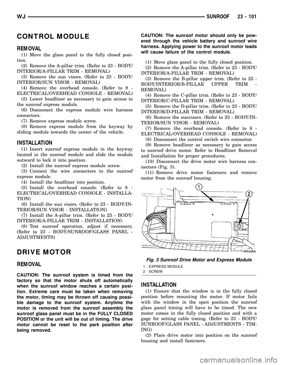
nectors (Fig. 3).
(11) Remove drive motor fasteners and remove
motor from the sunroof housing.
INSTALLATION
(1) Ensure that the window is in the fully closed
position before mounting the motor. If motor fails
with the window in the open position the sunroof
glass panel timing will have to be timed. The new
motor comes in the fully closed position and with a
gage for setting cable timing. (Refer to 23 - BODY/
SUNROOF/GLASS PANEL - ADJUSTMENTS - TIM-
ING)
(2) Place drive motor into position on the sunroof
housing and install fasteners.
Fig. 3 Sunroof Drive Motor and Express Module
1 - EXPRESS MODULE
2 - SCREW
WJSUNROOF 23 - 101
Page 1975 of 2199

(3) Connect express module, drive motor, and con-
trol switch wire connectors.
(4) Set headliner into position.
(5) Test sunroof operation, adjust as necessary.
(Refer to 23 - BODY/SUNROOF/GLASS PANEL -
ADJUSTMENTS)
(6) Finish installing the headliner.
(7) Connect the control switch wire connector.
(8) Install the overhead console. (Refer to 8 -
ELECTRICAL/OVERHEAD CONSOLE - INSTALLA-
TION)
(9) Install the sunvisors. (Refer to 23 - BODY/IN-
TERIOR/SUN VISOR - INSTALLATION)
(10) Install the D-pillar trim. (Refer to 23 - BODY/
INTERIOR/D-PILLAR TRIM - INSTALLATION)
(11) Install the C-pillar trim. (Refer to 23 - BODY/
INTERIOR/C-PILLAR TRIM - INSTALLATION)
(12) Install the B-pillar upper trim. (Refer to 23 -
BODY/INTERIOR/B-PILLAR UPPER TRIM -
INSTALLATION)
(13) Install the A-pillar trim. (Refer to 23 - BODY/
INTERIOR/A-PILLAR TRIM - INSTALLATION)
WIND DEFLECTOR
REMOVAL
(1) Open sunroof glass panel.
(2) Push down one corner of the wind deflector and
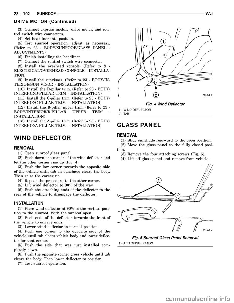
let the other corner rise up (Fig. 4).
(3) Push the low corner towards the opposite side
of the vehicle until tab on sunshade clears the body.
Then raise the corner up.
(4) Repeat the procedure to the other corner.
(5) Lift wind deflector to 90% of the way.
(6) Push the attaching ends of the deflector to the
rear of the vehicle to disengage the deflector.
INSTALLATION
(1) Place wind deflector at 90% in the vertical posi-
tion to the sunroof. With the sunroof open.
(2) Push ends of the deflector towards the front of
the vehicle to engage ends.
(3) Lower wind deflector to normal position.
(4) Push one corner to the opposite side of the
vehicle until tab clears vehicle body and lower deflec-
tor for that corner.
(5) Push the side that was just installed com-
pletely down.
(6) Push the opposite corner cross vehicle until tab
clears the body. Then lower deflector to position.
(7) Test sunroof operation.
GLASS PANEL
REMOVAL
(1) Slide sunshade rearward to the open position.
(2) Move the glass panel to the fully closed posi-
tion.
(3) Remove the four attaching screws (Fig. 5).
(4) Lift off glass panel and remove from vehicle.
Fig. 4 Wind Deflector
1 - WIND DEFLECTOR
2-TAB
Fig. 5 Sunroof Glass Panel Removal
1 - ATTACHING SCREW
23 - 102 SUNROOFWJ
DRIVE MOTOR (Continued)
Page 2026 of 2199

WELD LOCATIONS
SPECIFICATIONS
WELD LOCATIONS
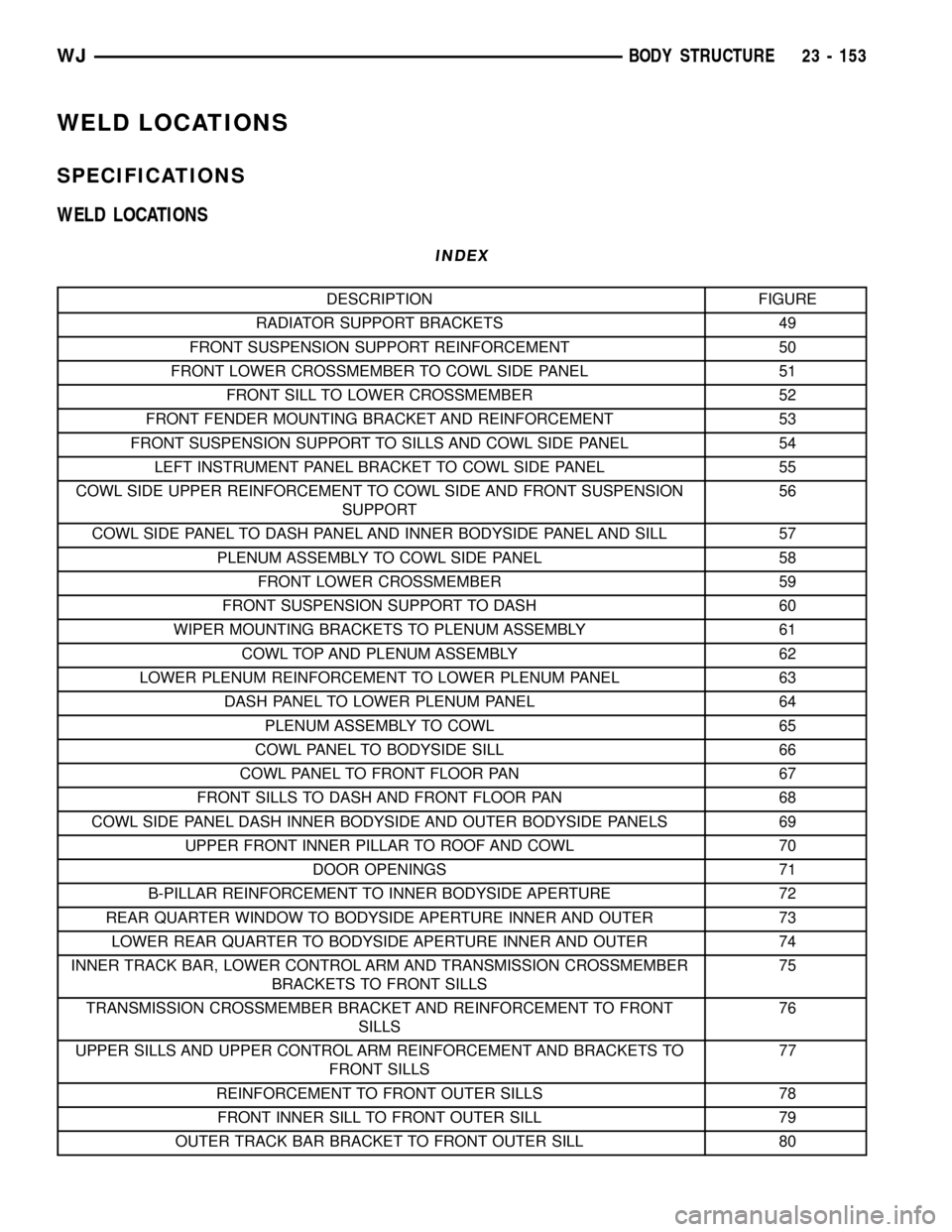
INDEX
DESCRIPTION FIGURE
RADIATOR SUPPORT BRACKETS 49
FRONT SUSPENSION SUPPORT REINFORCEMENT 50
FRONT LOWER CROSSMEMBER TO COWL SIDE PANEL 51
FRONT SILL TO LOWER CROSSMEMBER 52
FRONT FENDER MOUNTING BRACKET AND REINFORCEMENT 53
FRONT SUSPENSION SUPPORT TO SILLS AND COWL SIDE PANEL 54
LEFT INSTRUMENT PANEL BRACKET TO COWL SIDE PANEL 55
COWL SIDE UPPER REINFORCEMENT TO COWL SIDE AND FRONT SUSPENSION
SUPPORT56
COWL SIDE PANEL TO DASH PANEL AND INNER BODYSIDE PANEL AND SILL 57
PLENUM ASSEMBLY TO COWL SIDE PANEL 58
FRONT LOWER CROSSMEMBER 59
FRONT SUSPENSION SUPPORT TO DASH 60
WIPER MOUNTING BRACKETS TO PLENUM ASSEMBLY 61
COWL TOP AND PLENUM ASSEMBLY 62
LOWER PLENUM REINFORCEMENT TO LOWER PLENUM PANEL 63
DASH PANEL TO LOWER PLENUM PANEL 64
PLENUM ASSEMBLY TO COWL 65
COWL PANEL TO BODYSIDE SILL 66
COWL PANEL TO FRONT FLOOR PAN 67
FRONT SILLS TO DASH AND FRONT FLOOR PAN 68
COWL SIDE PANEL DASH INNER BODYSIDE AND OUTER BODYSIDE PANELS 69
UPPER FRONT INNER PILLAR TO ROOF AND COWL 70
DOOR OPENINGS 71
B-PILLAR REINFORCEMENT TO INNER BODYSIDE APERTURE 72
REAR QUARTER WINDOW TO BODYSIDE APERTURE INNER AND OUTER 73
LOWER REAR QUARTER TO BODYSIDE APERTURE INNER AND OUTER 74
INNER TRACK BAR, LOWER CONTROL ARM AND TRANSMISSION CROSSMEMBER
BRACKETS TO FRONT SILLS75
TRANSMISSION CROSSMEMBER BRACKET AND REINFORCEMENT TO FRONT
SILLS76
UPPER SILLS AND UPPER CONTROL ARM REINFORCEMENT AND BRACKETS TO
FRONT SILLS77
REINFORCEMENT TO FRONT OUTER SILLS 78
FRONT INNER SILL TO FRONT OUTER SILL 79
OUTER TRACK BAR BRACKET TO FRONT OUTER SILL 80
WJBODY STRUCTURE 23 - 153
Page 2027 of 2199

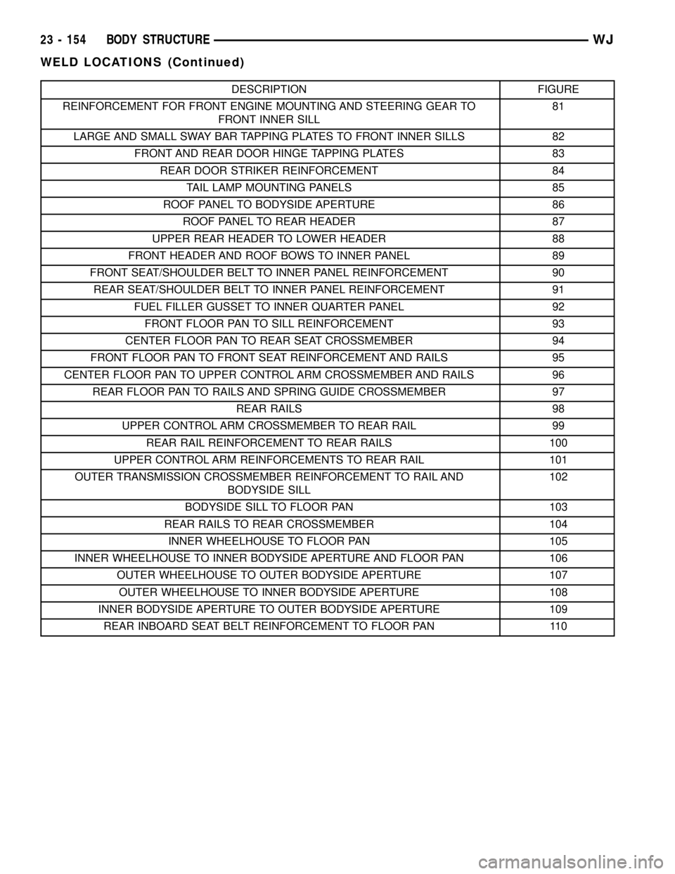
DESCRIPTION FIGURE
REINFORCEMENT FOR FRONT ENGINE MOUNTING AND STEERING GEAR TO
FRONT INNER SILL81
LARGE AND SMALL SWAY BAR TAPPING PLATES TO FRONT INNER SILLS 82
FRONT AND REAR DOOR HINGE TAPPING PLATES 83
REAR DOOR STRIKER REINFORCEMENT 84
TAIL LAMP MOUNTING PANELS 85
ROOF PANEL TO BODYSIDE APERTURE 86
ROOF PANEL TO REAR HEADER 87
UPPER REAR HEADER TO LOWER HEADER 88
FRONT HEADER AND ROOF BOWS TO INNER PANEL 89
FRONT SEAT/SHOULDER BELT TO INNER PANEL REINFORCEMENT 90
REAR SEAT/SHOULDER BELT TO INNER PANEL REINFORCEMENT 91
FUEL FILLER GUSSET TO INNER QUARTER PANEL 92
FRONT FLOOR PAN TO SILL REINFORCEMENT 93
CENTER FLOOR PAN TO REAR SEAT CROSSMEMBER 94
FRONT FLOOR PAN TO FRONT SEAT REINFORCEMENT AND RAILS 95
CENTER FLOOR PAN TO UPPER CONTROL ARM CROSSMEMBER AND RAILS 96
REAR FLOOR PAN TO RAILS AND SPRING GUIDE CROSSMEMBER 97
REAR RAILS 98
UPPER CONTROL ARM CROSSMEMBER TO REAR RAIL 99
REAR RAIL REINFORCEMENT TO REAR RAILS 100
UPPER CONTROL ARM REINFORCEMENTS TO REAR RAIL 101
OUTER TRANSMISSION CROSSMEMBER REINFORCEMENT TO RAIL AND
BODYSIDE SILL102
BODYSIDE SILL TO FLOOR PAN 103
REAR RAILS TO REAR CROSSMEMBER 104
INNER WHEELHOUSE TO FLOOR PAN 105
INNER WHEELHOUSE TO INNER BODYSIDE APERTURE AND FLOOR PAN 106
OUTER WHEELHOUSE TO OUTER BODYSIDE APERTURE 107
OUTER WHEELHOUSE TO INNER BODYSIDE APERTURE 108
INNER BODYSIDE APERTURE TO OUTER BODYSIDE APERTURE 109
REAR INBOARD SEAT BELT REINFORCEMENT TO FLOOR PAN 110
23 - 154 BODY STRUCTUREWJ
WELD LOCATIONS (Continued)
Page 2048 of 2199
Fig. 75 INNER TRACK BAR, LOWER CONTROL ARM AND TRANSMISSION CROSSMEMBER
BRACKETS TO FRONT SILLS
WJBODY STRUCTURE 23 - 175
WELD LOCATIONS (Continued)
Page 2050 of 2199
Fig. 77 UPPER SILLS AND UPPER CONTROL ARM REINFORCEMENT AND BRACKETS TO FRONT SILLS
WJBODY STRUCTURE 23 - 177
WELD LOCATIONS (Continued)
Page 2067 of 2199
Fig. 96 CENTER FLOOR PAN TO UPPER CONTROL ARM CROSSMEMBER AND RAILS
23 - 194 BODY STRUCTUREWJ
WELD LOCATIONS (Continued)
Page 2069 of 2199
Fig. 98 REAR RAILS
Fig. 99 UPPER CONTROL ARM CROSSMEMBER TO REAR RAIL
23 - 196 BODY STRUCTUREWJ
WELD LOCATIONS (Continued)