Page 1440 of 2199
Fig. 26 FUEL TANK AND COMPONENTS
1 - FUEL PUMP MODULE 9 - TANK SUPPORT BRACKET (SMALL/FRONT)
2 - MODULE LOCK RING 10 - MODULE PIGTAIL HARNESS
3 - TANK SUPPORT BRACKETS (REAR) 11 - FUEL SUPPLY (PRESSURE) LINE
4 - CHECK VALVE 12 - FUEL RETURN LINE
5 - FUEL FILL HOSE 13 - SKID PLATE
6 - ORVR COMPONENTS 14 - TANK STRAPS (2)
7 - ORVR CONTROL VALVE 15 - FUEL TANK
8 - CONTROL VALVE LOCK RING
WJFUEL DELIVERY 14 - 21
FUEL TANK (Continued)
Page 1441 of 2199
Fig. 27 ORVR CONTROL VALVE / LOCK RING
1 - ORVR CONTROL VALVE
2 - LOCK RING
3 - ORVR HOSE
4 - RELEASE TAB
5 - TOP OF FUEL TANK
Fig. 28 STONE SHIELD
1 - LEFT-REAR WHEELHOUSE
2 - STONE SHIELD
3 - PLASTIC RIVETS
Fig. 29 LDP MOUNTING BOLTS
1 - SUPPORT BRACKET NUTS (2)
2 - SUPPORT BRACKET (FRONT)
3 - SUPPORT BRACKET BRACE BOLT
4 - LDP MOUNTING BOLTS (3)
Fig. 30 TWO-PIECE SUPPORT BRACKET
1 - TWO-PIECE SUPPORT BRACKET (FRONT)
2 - SUPPORT BRACKET BRACE
3 - TWO-PIECE SUPPORT BRACKET (REAR)
4 - SUPPORT BRACKET ATTACHING BOLTS (3)
5 - SUPPORT BRACKET BRACE BOLT
14 - 22 FUEL DELIVERYWJ
FUEL TANK (Continued)
Page 1442 of 2199
Fig. 31 LDP REMOVAL / INSTALLATION
1 - LDP
2 - ELEC. CONNECT.
3 - VAPOR / VACUUM LINES
4 - WIRING CLIP
Fig. 32 FUEL FILL TUBE/HOSE/CLAMP
1 - AXLE VENT HOSE
2 - FUEL VENT TUBE
3 - FUEL FILL TUBE
4 - PLASTIC TIE WRAP
5 - HOSE CLAMP
6 - FUEL FILL HOSE
7 - FUEL VENT HOSE
Fig. 33 ORVR HOSE ELBOW
1 - FUEL FILL HOSE
2 - ELBOW (TO TOP OF EVAP CANISTER)
Fig. 34 BUMPER FASCIA CLIPS
1 - CLIPS
2 - FUEL TANK
WJFUEL DELIVERY 14 - 23
FUEL TANK (Continued)
Page 1443 of 2199
Fig. 35 FUEL TANK HEAT SHIELD BOLTS
1 - FUEL TANK
2 - HEAT SHIELD BOLTS
Fig. 36 FUEL FILTER/FUEL PRESSURE REGULATOR
1 - FUEL RETURN LINE
2 - FUEL SUPPLY LINE (TO FUEL RAIL)
3 - FUEL FILTER/FUEL PRESSURE REGULATOR
4 - FUEL PRESSURE LINE
5 - REAR AXLE
6 - ELEC. CONNECTOR
7 - EVAP LINE
14 - 24 FUEL DELIVERYWJ
FUEL TANK (Continued)
Page 1444 of 2199
Fig. 37 BRACKET, TANK SUPPORT - FRONT
1 - FUEL TANK SUPPORT BRACKET (LEFT FRONT)
2 - BRACKET BOLT
3 - LEFT SIDE OF TANK
Fig. 38 BRACKETS, TANK SUPPORT - REAR
1 - TOW HOOKS
2 - REAR SUPPORT BRACKETS (2)
3 - TANK SUPPORT BRACKET NUTS
4 - TANK SUPPORT BRACKET BOLTS
Fig. 39 FUEL TANK MOUNTING - NO TRAILER
HITCH
1 - TANK MOUNTING BOLTS
2 - STRAP NUTS
3 - FUEL TANK/SHIELD ASSEMBLY
WJFUEL DELIVERY 14 - 25
FUEL TANK (Continued)
Page 1445 of 2199
Fig. 40 FUEL TANK MOUNTING - WITH TRAILER HITCH
1 - TRAILER HITCH
2 - FUEL TANK3 - FUEL TANK / HITCH MOUNTING BOLTS
Fig. 41 FUEL FILLER TUBE
1 - FUEL FILLER TUBE
2 - MOUNTING BOLTS (3)
14 - 26 FUEL DELIVERYWJ
FUEL TANK (Continued)
Page 1446 of 2199

INLET FILTER
REMOVAL
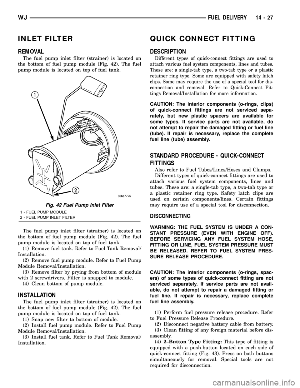
The fuel pump inlet filter (strainer) is located on
the bottom of fuel pump module (Fig. 42). The fuel
pump module is located on top of fuel tank.
The fuel pump inlet filter (strainer) is located on
the bottom of fuel pump module (Fig. 42). The fuel
pump module is located on top of fuel tank.
(1) Remove fuel tank. Refer to Fuel Tank Removal/
Installation.
(2) Remove fuel pump module. Refer to Fuel Pump
Module Removal/Installation.
(3) Remove filter by prying from bottom of module
with 2 screwdrivers. Filter is snapped to module.
(4) Clean bottom of pump module.
INSTALLATION
The fuel pump inlet filter (strainer) is located on
the bottom of fuel pump module (Fig. 42). The fuel
pump module is located on top of fuel tank.
(1) Snap new filter to bottom of module.
(2) Install fuel pump module. Refer to Fuel Pump
Module Removal/Installation.
(3) Install fuel tank. Refer to Fuel Tank Removal/
Installation.
QUICK CONNECT FITTING
DESCRIPTION
Different types of quick-connect fittings are used to
attach various fuel system components, lines and tubes.
These are: a single-tab type, a two-tab type or a plastic
retainer ring type. Some are equipped with safety latch
clips. Some may require the use of a special tool for dis-
connection and removal. Refer to Quick-Connect Fit-
tings Removal/Installation for more information.
CAUTION: The interior components (o-rings, clips)
of quick-connect fittings are not serviced sepa-
rately, but new plastic spacers are available for
some types. If service parts are not available, do
not attempt to repair the damaged fitting or fuel line
(tube). If repair is necessary, replace the complete
fuel line (tube) assembly.
STANDARD PROCEDURE - QUICK-CONNECT
FITTINGS
Also refer to Fuel Tubes/Lines/Hoses and Clamps.
Different types of quick-connect fittings are used to
attach various fuel system components, lines and
tubes. These are: a single-tab type, a two-tab type or
a plastic retainer ring type. Safety latch clips are
used on certain components/lines. Certain fittings
may require use of a special tool for disconnection.
DISCONNECTING
WARNING: THE FUEL SYSTEM IS UNDER A CON-
STANT PRESSURE (EVEN WITH ENGINE OFF).
BEFORE SERVICING ANY FUEL SYSTEM HOSE,
FITTING OR LINE, FUEL SYSTEM PRESSURE MUST
BE RELEASED. REFER TO FUEL SYSTEM PRES-
SURE RELEASE PROCEDURE.
CAUTION: The interior components (o-rings, spac-
ers) of some types of quick-connect fitting are not
serviced separately. If service parts are not avail-
able, do not attempt to repair a damaged fitting or
fuel line. If repair is necessary, replace complete
fuel line assembly.
(1) Perform fuel pressure release procedure. Refer
to Fuel Pressure Release Procedure.
(2) Disconnect negative battery cable from battery.
(3) Clean fitting of any foreign material before dis-
assembly.
(4)2±Button Type Fitting:This type of fitting is
equipped with a push-button located on each side of
quick-connect fitting (Fig. 43). Press on both buttons
simultaneously for removal. Special tools are not
required for disconnection.
Fig. 42 Fuel Pump Inlet Filter
1 - FUEL PUMP MODULE
2 - FUEL PUMP INLET FILTER
WJFUEL DELIVERY 14 - 27
Page 1451 of 2199

FUEL INJECTION
DIAGNOSIS AND TESTING
VISUAL INSPECTION
A visual inspection for loose, disconnected or incor-
rectly routed wires, vacuum lines and hoses should
be made. This should be done before attempting to
diagnose or service the fuel injection system. A visual
check will help spot these faults and save unneces-
sary test and diagnostic time. A thorough visual
inspection will include the following checks:
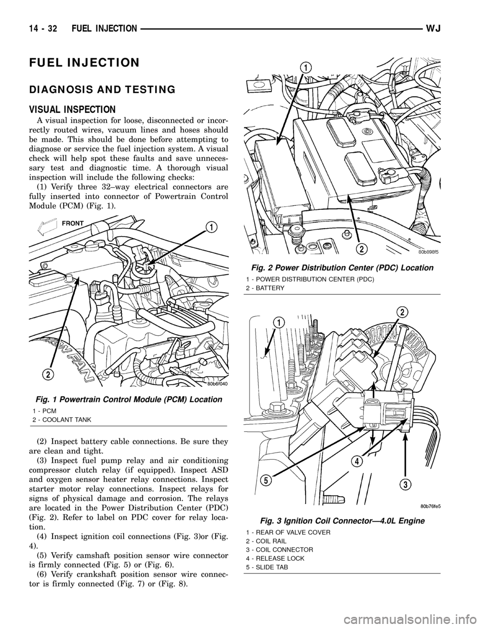
(1) Verify three 32±way electrical connectors are
fully inserted into connector of Powertrain Control
Module (PCM) (Fig. 1).
(2) Inspect battery cable connections. Be sure they
are clean and tight.
(3) Inspect fuel pump relay and air conditioning
compressor clutch relay (if equipped). Inspect ASD
and oxygen sensor heater relay connections. Inspect
starter motor relay connections. Inspect relays for
signs of physical damage and corrosion. The relays
are located in the Power Distribution Center (PDC)
(Fig. 2). Refer to label on PDC cover for relay loca-
tion.
(4) Inspect ignition coil connections (Fig. 3)or (Fig.
4).
(5) Verify camshaft position sensor wire connector
is firmly connected (Fig. 5) or (Fig. 6).
(6) Verify crankshaft position sensor wire connec-
tor is firmly connected (Fig. 7) or (Fig. 8).
Fig. 1 Powertrain Control Module (PCM) Location
1 - PCM
2 - COOLANT TANK
Fig. 2 Power Distribution Center (PDC) Location
1 - POWER DISTRIBUTION CENTER (PDC)
2 - BATTERY
Fig. 3 Ignition Coil ConnectorÐ4.0L Engine
1 - REAR OF VALVE COVER
2 - COIL RAIL
3 - COIL CONNECTOR
4 - RELEASE LOCK
5 - SLIDE TAB
14 - 32 FUEL INJECTIONWJ