2002 JEEP GRAND CHEROKEE Cooling fan
[x] Cancel search: Cooling fanPage 1359 of 2199
(8) Remove radiator cooling fan and shroud (Refer
to 7 - COOLING/ENGINE/RADIATOR FAN -
REMOVAL).
(9) Remove crankshaft damper bolt.
(10) Remove damper using Special Tools 8513
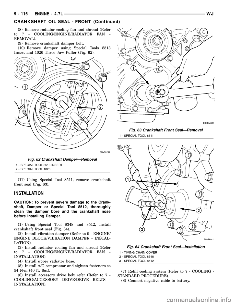
Insert and 1026 Three Jaw Puller (Fig. 62).
(11) Using Special Tool 8511, remove crankshaft
front seal (Fig. 63).
INSTALLATION
CAUTION: To prevent severe damage to the Crank-
shaft, Damper or Special Tool 8512, thoroughly
clean the damper bore and the crankshaft nose
before installing Damper.
(1) Using Special Tool 8348 and 8512, install
crankshaft front seal (Fig. 64).
(2) Install vibration damper (Refer to 9 - ENGINE/
ENGINE BLOCK/VIBRATION DAMPER - INSTAL-
LATION).
(3) Install radiator cooling fan and shroud (Refer
to 7 - COOLING/ENGINE/RADIATOR FAN -
INSTALLATION).
(4) Install upper radiator hose.
(5) Install A/C compressor and tighten fasteners to
54 N´m (40 ft. lbs.).
(6) Install accessory drive belt refer (Refer to 7 -
COOLING/ACCESSORY DRIVE/DRIVE BELTS -
INSTALLATION).(7) Refill cooling system (Refer to 7 - COOLING -
STANDARD PROCEDURE).
(8) Connect negative cable to battery.
Fig. 62 Crankshaft DamperÐRemoval
1 - SPECIAL TOOL 8513 INSERT
2 - SPECIAL TOOL 1026
Fig. 63 Crankshaft Front SealÐRemoval
1 - SPECIAL TOOL 8511
Fig. 64 Crankshaft Front SealÐInstallation
1 - TIMING CHAIN COVER
2 - SPECIAL TOOL 8348
3 - SPECIAL TOOL 8512
9 - 116 ENGINE - 4.7LWJ
CRANKSHAFT OIL SEAL - FRONT (Continued)
Page 1390 of 2199
TIMING BELT/CHAIN AND
SPROCKETS
REMOVAL
(1) Disconnect negative cable from battery.
(2) Drain cooling system (Refer to 7 - COOLING -
STANDARD PROCEDURE).
(3) Remove right and left cylinder head covers
(Refer to 9 - ENGINE/CYLINDER HEAD/CYLIN-
DER HEAD COVER(S) - REMOVAL).
(4) Remove radiator fan (Refer to 7 - COOLING/
ENGINE/RADIATOR FAN - REMOVAL).
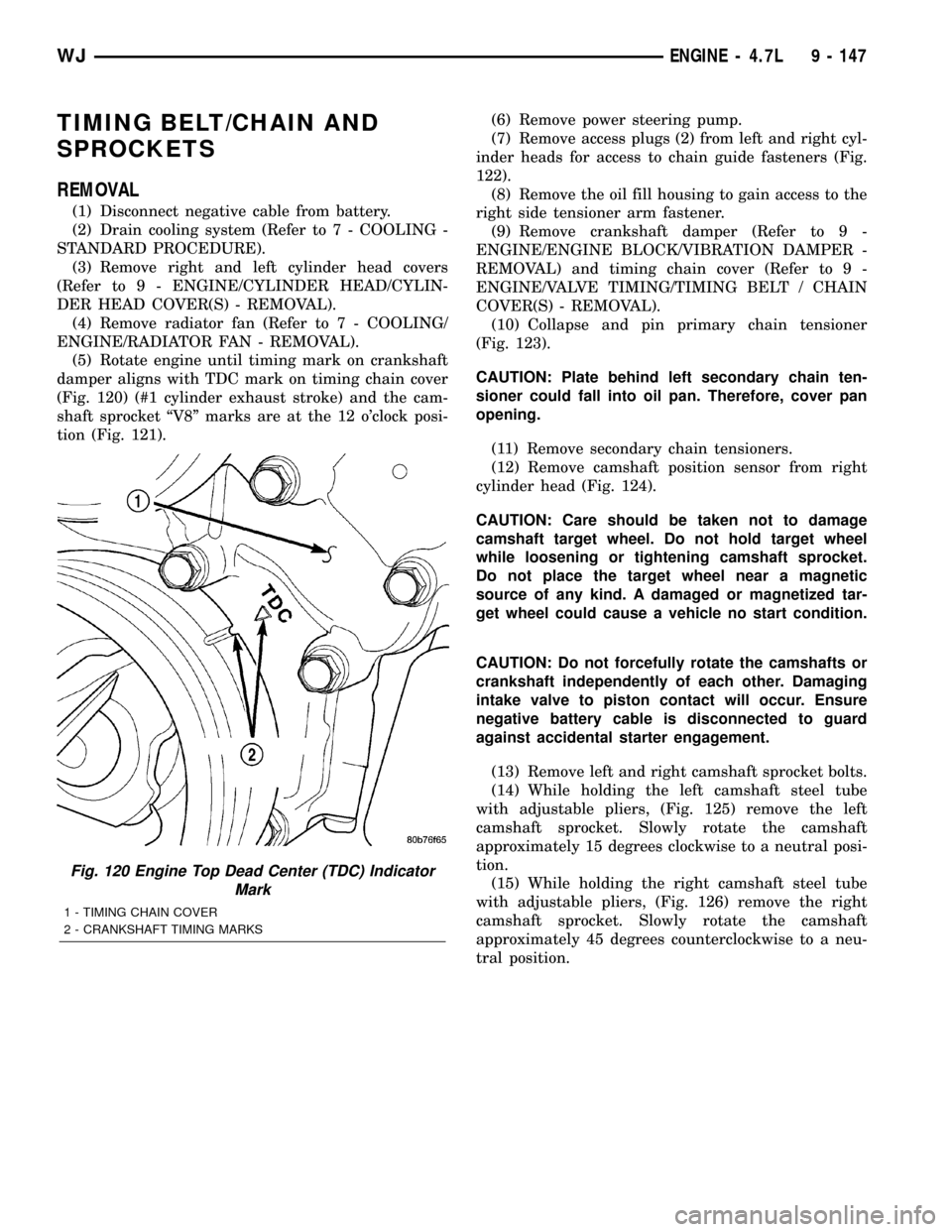
(5) Rotate engine until timing mark on crankshaft
damper aligns with TDC mark on timing chain cover
(Fig. 120) (#1 cylinder exhaust stroke) and the cam-
shaft sprocket ªV8º marks are at the 12 o'clock posi-
tion (Fig. 121).(6) Remove power steering pump.
(7) Remove access plugs (2) from left and right cyl-
inder heads for access to chain guide fasteners (Fig.
122).
(8) Remove the oil fill housing to gain access to the
right side tensioner arm fastener.
(9) Remove crankshaft damper (Refer to 9 -
ENGINE/ENGINE BLOCK/VIBRATION DAMPER -
REMOVAL) and timing chain cover (Refer to 9 -
ENGINE/VALVE TIMING/TIMING BELT / CHAIN
COVER(S) - REMOVAL).
(10) Collapse and pin primary chain tensioner
(Fig. 123).
CAUTION: Plate behind left secondary chain ten-
sioner could fall into oil pan. Therefore, cover pan
opening.
(11) Remove secondary chain tensioners.
(12) Remove camshaft position sensor from right
cylinder head (Fig. 124).
CAUTION: Care should be taken not to damage
camshaft target wheel. Do not hold target wheel
while loosening or tightening camshaft sprocket.
Do not place the target wheel near a magnetic
source of any kind. A damaged or magnetized tar-
get wheel could cause a vehicle no start condition.
CAUTION: Do not forcefully rotate the camshafts or
crankshaft independently of each other. Damaging
intake valve to piston contact will occur. Ensure
negative battery cable is disconnected to guard
against accidental starter engagement.
(13) Remove left and right camshaft sprocket bolts.
(14) While holding the left camshaft steel tube
with adjustable pliers, (Fig. 125) remove the left
camshaft sprocket. Slowly rotate the camshaft
approximately 15 degrees clockwise to a neutral posi-
tion.
(15) While holding the right camshaft steel tube
with adjustable pliers, (Fig. 126) remove the right
camshaft sprocket. Slowly rotate the camshaft
approximately 45 degrees counterclockwise to a neu-
tral position.
Fig. 120 Engine Top Dead Center (TDC) Indicator
Mark
1 - TIMING CHAIN COVER
2 - CRANKSHAFT TIMING MARKS
WJENGINE - 4.7L 9 - 147
Page 1396 of 2199
(22) Install timing chain cover (Refer to 9 -
ENGINE/VALVE TIMING/TIMING BELT / CHAIN
COVER(S) - INSTALLATION) and crankshaft
damper (Refer to 9 - ENGINE/ENGINE BLOCK/VI-
BRATION DAMPER - INSTALLATION).
(23) Install cylinder head covers (Refer to 9 -
ENGINE/CYLINDER HEAD/CYLINDER HEAD
COVER(S) - INSTALLATION).
NOTE: Before installing threaded plug in right cylin-
der head, the plug must be coated with sealant to
prevent leaks.
(24) Coat the large threaded access plug with
MopartThread Sealant with Teflon, then install
into the right cylinder head and tighten to 81 N´m
(60 ft. lbs.) (Fig. 122).
(25) Install the oil fill housing.
(26) Install access plug in left cylinder head (Fig.
122).
(27) Install power steering pump.
(28) Install radiator fan (Refer to 7 - COOLING/
ENGINE/RADIATOR FAN - INSTALLATION).
(29) Fill cooling system (Refer to 7 - COOLING -
STANDARD PROCEDURE).
(30) Connect negative cable to battery.
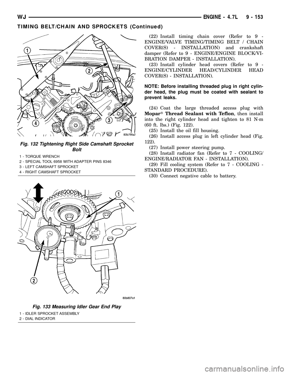
Fig. 132 Tightening Right Side Camshaft Sprocket
Bolt
1 - TORQUE WRENCH
2 - SPECIAL TOOL 6958 WITH ADAPTER PINS 8346
3 - LEFT CAMSHAFT SPROCKET
4 - RIGHT CAMSHAFT SPROCKET
Fig. 133 Measuring Idler Gear End Play
1 - IDLER SPROCKET ASSEMBLY
2 - DIAL INDICATOR
WJENGINE - 4.7L 9 - 153
TIMING BELT/CHAIN AND SPROCKETS (Continued)
Page 1458 of 2199
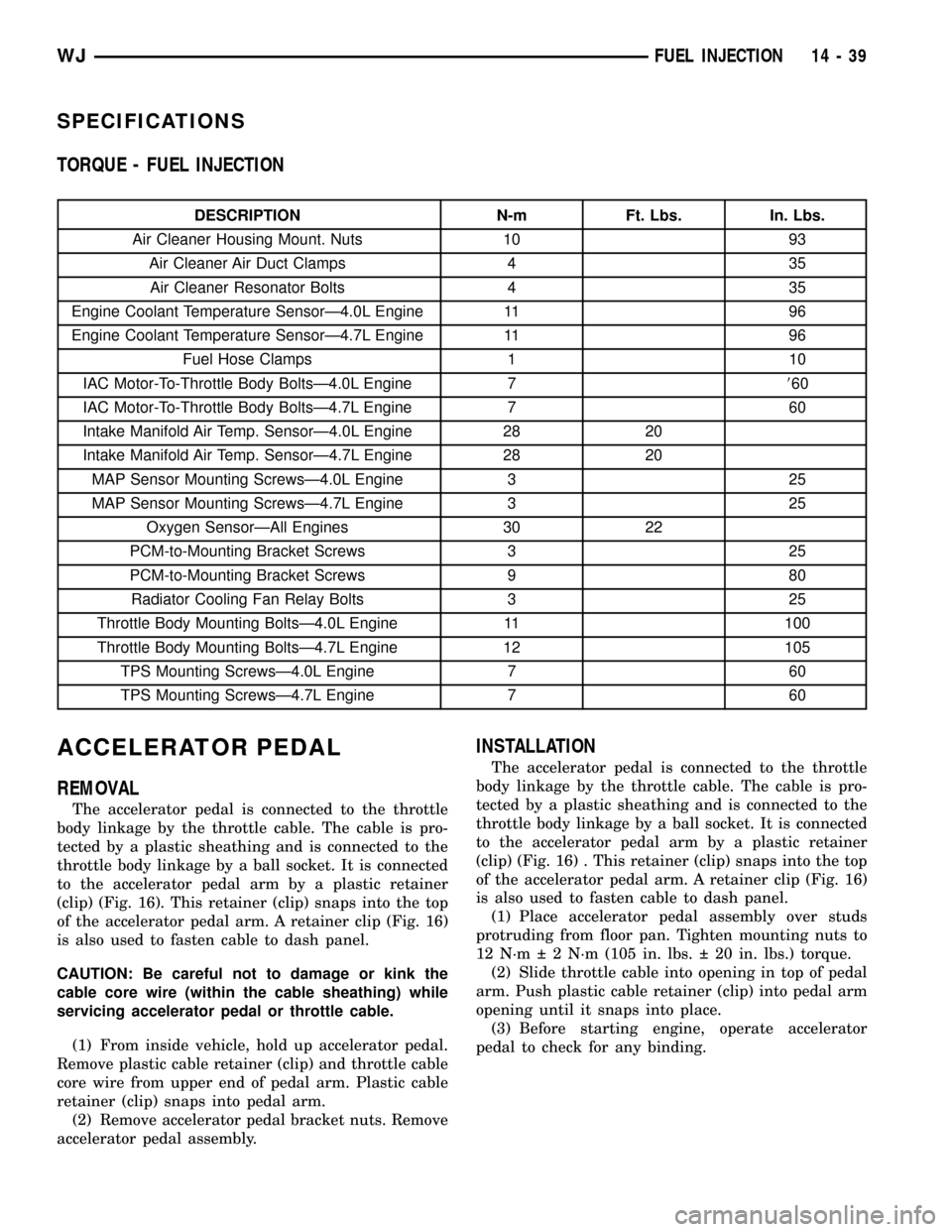
SPECIFICATIONS
TORQUE - FUEL INJECTION
DESCRIPTION N-m Ft. Lbs. In. Lbs.
Air Cleaner Housing Mount. Nuts 10 93
Air Cleaner Air Duct Clamps 4 35
Air Cleaner Resonator Bolts 4 35
Engine Coolant Temperature SensorÐ4.0L Engine 11 96
Engine Coolant Temperature SensorÐ4.7L Engine 11 96
Fuel Hose Clamps 1 10
IAC Motor-To-Throttle Body BoltsÐ4.0L Engine 7860
IAC Motor-To-Throttle Body BoltsÐ4.7L Engine 7 60
Intake Manifold Air Temp. SensorÐ4.0L Engine 28 20
Intake Manifold Air Temp. SensorÐ4.7L Engine 28 20
MAP Sensor Mounting ScrewsÐ4.0L Engine 3 25
MAP Sensor Mounting ScrewsÐ4.7L Engine 3 25
Oxygen SensorÐAll Engines 30 22
PCM-to-Mounting Bracket Screws 3 25
PCM-to-Mounting Bracket Screws 9 80
Radiator Cooling Fan Relay Bolts 3 25
Throttle Body Mounting BoltsÐ4.0L Engine 11 100
Throttle Body Mounting BoltsÐ4.7L Engine 12 105
TPS Mounting ScrewsÐ4.0L Engine 7 60
TPS Mounting ScrewsÐ4.7L Engine 7 60
ACCELERATOR PEDAL
REMOVAL
The accelerator pedal is connected to the throttle
body linkage by the throttle cable. The cable is pro-
tected by a plastic sheathing and is connected to the
throttle body linkage by a ball socket. It is connected
to the accelerator pedal arm by a plastic retainer
(clip) (Fig. 16). This retainer (clip) snaps into the top
of the accelerator pedal arm. A retainer clip (Fig. 16)
is also used to fasten cable to dash panel.
CAUTION: Be careful not to damage or kink the
cable core wire (within the cable sheathing) while
servicing accelerator pedal or throttle cable.
(1) From inside vehicle, hold up accelerator pedal.
Remove plastic cable retainer (clip) and throttle cable
core wire from upper end of pedal arm. Plastic cable
retainer (clip) snaps into pedal arm.
(2) Remove accelerator pedal bracket nuts. Remove
accelerator pedal assembly.
INSTALLATION
The accelerator pedal is connected to the throttle
body linkage by the throttle cable. The cable is pro-
tected by a plastic sheathing and is connected to the
throttle body linkage by a ball socket. It is connected
to the accelerator pedal arm by a plastic retainer
(clip) (Fig. 16) . This retainer (clip) snaps into the top
of the accelerator pedal arm. A retainer clip (Fig. 16)
is also used to fasten cable to dash panel.
(1) Place accelerator pedal assembly over studs
protruding from floor pan. Tighten mounting nuts to
12 N´m 2 N´m (105 in. lbs. 20 in. lbs.) torque.
(2) Slide throttle cable into opening in top of pedal
arm. Push plastic cable retainer (clip) into pedal arm
opening until it snaps into place.
(3) Before starting engine, operate accelerator
pedal to check for any binding.
WJFUEL INJECTION 14 - 39
Page 1509 of 2199
PUMP
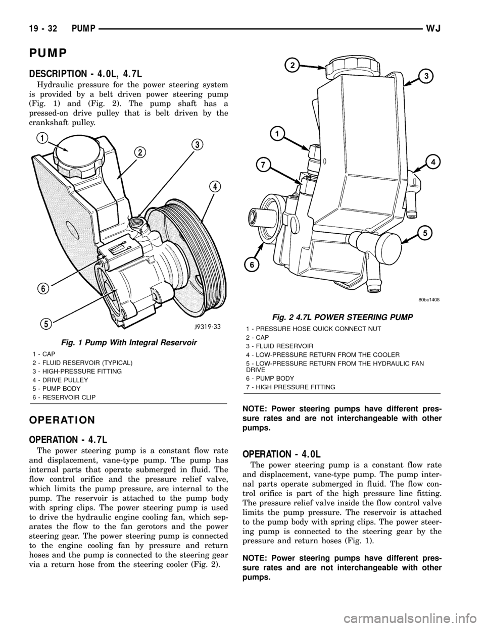
DESCRIPTION - 4.0L, 4.7L
Hydraulic pressure for the power steering system
is provided by a belt driven power steering pump
(Fig. 1) and (Fig. 2). The pump shaft has a
pressed-on drive pulley that is belt driven by the
crankshaft pulley.
OPERATION
OPERATION - 4.7L
The power steering pump is a constant flow rate
and displacement, vane-type pump. The pump has
internal parts that operate submerged in fluid. The
flow control orifice and the pressure relief valve,
which limits the pump pressure, are internal to the
pump. The reservoir is attached to the pump body
with spring clips. The power steering pump is used
to drive the hydraulic engine cooling fan, which sep-
arates the flow to the fan gerotors and the power
steering gear. The power steering pump is connected
to the engine cooling fan by pressure and return
hoses and the pump is connected to the steering gear
via a return hose from the steering cooler (Fig. 2).NOTE: Power steering pumps have different pres-
sure rates and are not interchangeable with other
pumps.OPERATION - 4.0L
The power steering pump is a constant flow rate
and displacement, vane-type pump. The pump inter-
nal parts operate submerged in fluid. The flow con-
trol orifice is part of the high pressure line fitting.
The pressure relief valve inside the flow control valve
limits the pump pressure. The reservoir is attached
to the pump body with spring clips. The power steer-
ing pump is connected to the steering gear by the
pressure and return hoses (Fig. 1).
NOTE: Power steering pumps have different pres-
sure rates and are not interchangeable with other
pumps.
Fig. 1 Pump With Integral Reservoir
1 - CAP
2 - FLUID RESERVOIR (TYPICAL)
3 - HIGH-PRESSURE FITTING
4 - DRIVE PULLEY
5 - PUMP BODY
6 - RESERVOIR CLIP
Fig. 2 4.7L POWER STEERING PUMP
1 - PRESSURE HOSE QUICK CONNECT NUT
2 - CAP
3 - FLUID RESERVOIR
4 - LOW-PRESSURE RETURN FROM THE COOLER
5 - LOW-PRESSURE RETURN FROM THE HYDRAULIC FAN
DRIVE
6 - PUMP BODY
7 - HIGH PRESSURE FITTING
19 - 32 PUMPWJ
Page 1511 of 2199
(11) While the vehicle is in park, use the DRB III
to activate the hydraulic fan to full fan operation and
briefly rev the engine up to 3000 rpm to fully engage
the hydraulic fan.
(12) Check the fluid level add if necessary.
REMOVAL
REMOVAL - 4.0L ENGINE
(1) Remove serpentine drive belt,(Refer to 7 -
COOLING/ACCESSORY DRIVE/DRIVE BELTS -
REMOVAL).
(2) Remove pressure and return hoses from pump
and drain the pump.
(3)
Loosen the pump bracket bolt at the engine block.
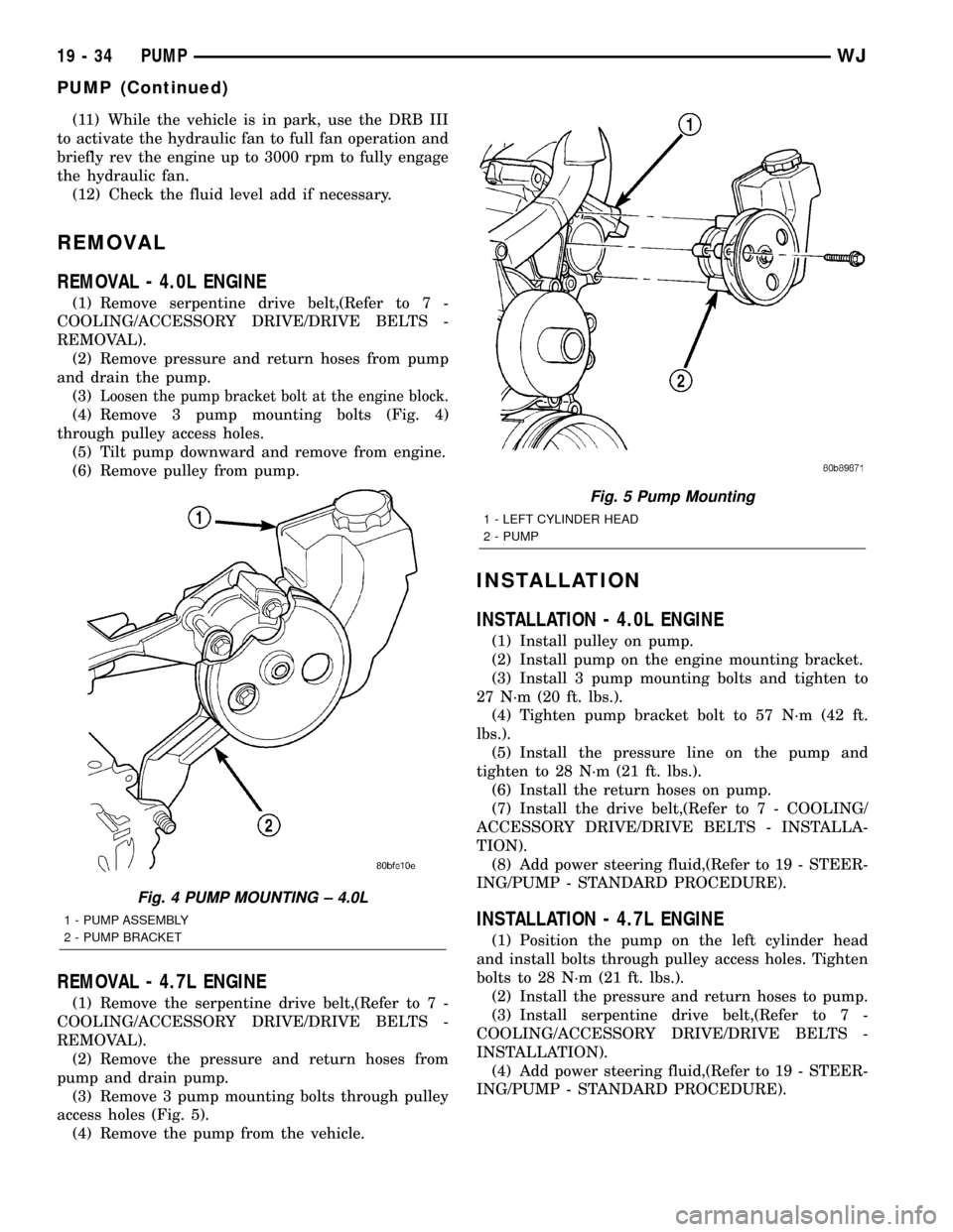
(4) Remove 3 pump mounting bolts (Fig. 4)
through pulley access holes.
(5) Tilt pump downward and remove from engine.
(6) Remove pulley from pump.
REMOVAL - 4.7L ENGINE
(1) Remove the serpentine drive belt,(Refer to 7 -
COOLING/ACCESSORY DRIVE/DRIVE BELTS -
REMOVAL).
(2) Remove the pressure and return hoses from
pump and drain pump.
(3) Remove 3 pump mounting bolts through pulley
access holes (Fig. 5).
(4) Remove the pump from the vehicle.
INSTALLATION
INSTALLATION - 4.0L ENGINE
(1) Install pulley on pump.
(2) Install pump on the engine mounting bracket.
(3) Install 3 pump mounting bolts and tighten to
27 N´m (20 ft. lbs.).
(4) Tighten pump bracket bolt to 57 N´m (42 ft.
lbs.).
(5) Install the pressure line on the pump and
tighten to 28 N´m (21 ft. lbs.).
(6) Install the return hoses on pump.
(7) Install the drive belt,(Refer to 7 - COOLING/
ACCESSORY DRIVE/DRIVE BELTS - INSTALLA-
TION).
(8) Add power steering fluid,(Refer to 19 - STEER-
ING/PUMP - STANDARD PROCEDURE).
INSTALLATION - 4.7L ENGINE
(1) Position the pump on the left cylinder head
and install bolts through pulley access holes. Tighten
bolts to 28 N´m (21 ft. lbs.).
(2) Install the pressure and return hoses to pump.
(3) Install serpentine drive belt,(Refer to 7 -
COOLING/ACCESSORY DRIVE/DRIVE BELTS -
INSTALLATION).
(4) Add power steering fluid,(Refer to 19 - STEER-
ING/PUMP - STANDARD PROCEDURE).
Fig. 4 PUMP MOUNTING ± 4.0L
1 - PUMP ASSEMBLY
2 - PUMP BRACKET
Fig. 5 Pump Mounting
1 - LEFT CYLINDER HEAD
2 - PUMP
19 - 34 PUMPWJ
PUMP (Continued)
Page 1514 of 2199
INSTALLATION
(1) Position and install the power steering cooler
to the vehicle.
(2) Install the three mounting bracket bolts (Fig.
6).
(3) Reconnect the upper hose at cooler (Fig. 6).
(4) Reconnect the lower hose at cooler (Fig. 6).
(5) Connect negative battery cable to battery.
(6) Refill the power steering fluid and bleed the
system,(Refer to 19 - STEERING/PUMP - STAN-
DARD PROCEDURE).
(7) Start engine and check for leaks.
(8) Install the grille opening reinforcement panel
(9) Install the front fascia grille,(Refer to 13 -
FRAMES & BUMPERS/BUMPERS/FRONT FASCIA
- INSTALLATION).
HOSES - 4.0L
DESCRIPTION
DESCRIPTION - PRESSURE LINE
The hose consists of two metal ends and rubber
center section that contains a tuning cable. The
pump end uses a quick connect fitting. Lubircation
must be used on the quick connect nut and o-ring
when installing.
DESCRIPTION - RETURN LINE
Power steering return line is a hose which is
clamped at the pump and the gear.
OPERATION
OPERATION - PRESSURE LINE
Power steering pressure line, is used to transfer
high pressure power steering fluid, from the power
steering pump to the power steering gear on the
4.0L. The 4.7L power steering pressure line, is used
to transfer high pressure power steering fluid, from
the power steering pump to the engine cooling fan
and the steering gear.
OPERATION - RETURN LINE
Power steering return line, is used to transfer low
pressure power steering fluid, from the power steer-
ing gear to the power steering pump.
REMOVAL
(1) Drain the power steering fluid from the reser-
voir.
(2) Remove the air box,(Refer to 9 - ENGINE/AIR
INTAKE SYSTEM/AIR CLEANER HOUSING -
REMOVAL).
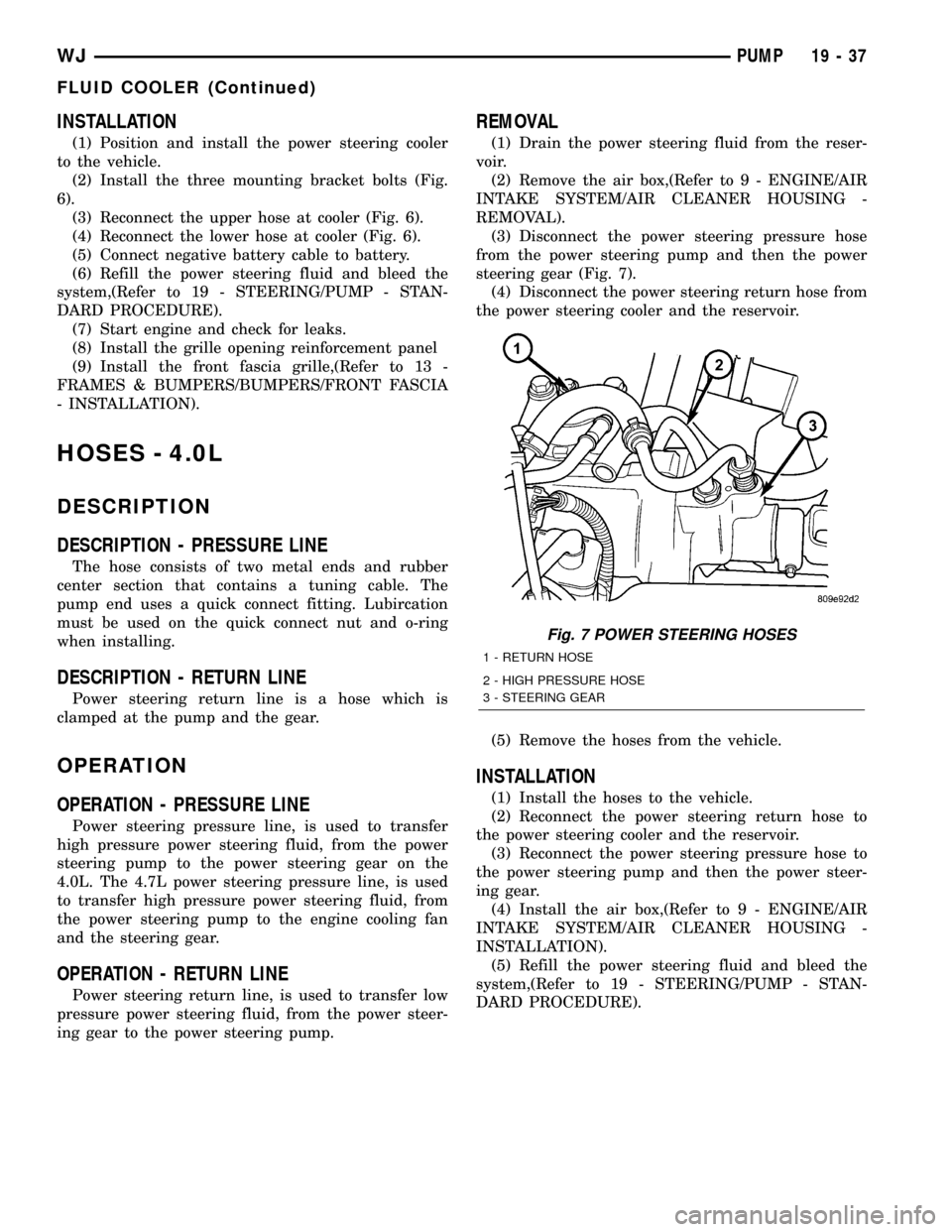
(3) Disconnect the power steering pressure hose
from the power steering pump and then the power
steering gear (Fig. 7).
(4) Disconnect the power steering return hose from
the power steering cooler and the reservoir.
(5) Remove the hoses from the vehicle.
INSTALLATION
(1) Install the hoses to the vehicle.
(2) Reconnect the power steering return hose to
the power steering cooler and the reservoir.
(3) Reconnect the power steering pressure hose to
the power steering pump and then the power steer-
ing gear.
(4) Install the air box,(Refer to 9 - ENGINE/AIR
INTAKE SYSTEM/AIR CLEANER HOUSING -
INSTALLATION).
(5) Refill the power steering fluid and bleed the
system,(Refer to 19 - STEERING/PUMP - STAN-
DARD PROCEDURE).
Fig. 7 POWER STEERING HOSES
1 - RETURN HOSE
2 - HIGH PRESSURE HOSE
3 - STEERING GEAR
WJPUMP 19 - 37
FLUID COOLER (Continued)
Page 1515 of 2199
HOSES - 4.7L
DESCRIPTION
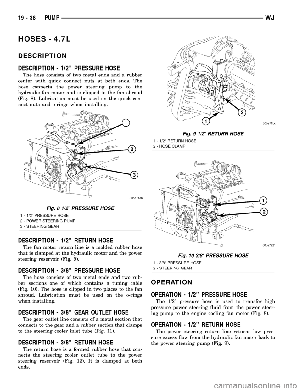
DESCRIPTION - 1/2º PRESSURE HOSE
The hose consists of two metal ends and a rubber
center with quick connect nuts at both ends. The
hose connects the power steering pump to the
hydraulic fan motor and is clipped to the fan shroud
(Fig. 8). Lubrication must be used on the quick con-
nect nuts and o-rings when installing.
DESCRIPTION - 1/2º RETURN HOSE
The fan motor return line is a molded rubber hose
that is clamped at the hydraulic motor and the power
steering reservoir (Fig. 9).
DESCRIPTION - 3/8º PRESSURE HOSE
The hose consists of two metal ends and two rub-
ber sections one of which contains a tuning cable
(Fig. 10). The hose is clipped in two places to the fan
shroud. Lubrication must be used on the o-rings
when installing.
DESCRIPTION - 3/8º GEAR OUTLET HOSE
The gear outlet line consists of a metal section that
connects to the gear and a rubber section that clamps
to the steering cooler inlet tube (Fig. 11).
DESCRIPTION - 3/8º RETURN HOSE
The return hose is a formed rubber hose that con-
nects the steering cooler outlet tube to the power
steering reservoir (Fig. 12). It is clamped at both
ends.
OPERATION
OPERATION - 1/2º PRESSURE HOSE
The 1/2º pressure hose is used to transfer high
pressure power steering fluid from the power steer-
ing pump to the engine cooling fan motor (Fig. 8).
OPERATION - 1/2º RETURN HOSE
The power steering return line returns low pres-
sure excess flow from the hydraulic fan motor back to
the power steering pump (Fig. 9).
Fig. 8 1/2(PRESSURE HOSE
1 - 1/29PRESSURE HOSE
2 - POWER STEERING PUMP
3 - STEERING GEAR
Fig. 9 1/2(RETURN HOSE
1 - 1/29RETURN HOSE
2 - HOSE CLAMP
Fig. 10 3/8(PRESSURE HOSE
1 - 3/89PRESSURE HOSE
2 - STEERING GEAR
19 - 38 PUMPWJ