2002 JEEP GRAND CHEROKEE Color
[x] Cancel search: ColorPage 1294 of 2199
crankshaft is drilled internally to pass oil from the
main bearing journals (except number 4 main bear-
ing journal) to the connecting rod journals. Each con-
necting rod bearing cap has a small squirt hole, oil
passes through the squirt hole and is thrown off as
the rod rotates. This oil throwoff lubricates the cam-
shaft lobes, distributor drive gear, cylinder walls, and
piston pins.
The hydraulic valve tappets receive oil directly
from the main oil gallery. Oil is provided to the cam-
shaft bearing through galleries. The front camshaft
bearing journal passes oil through the camshaft
sprocket to the timing chain. Oil drains back to the
oil pan under the number one main bearing cap.
The oil supply for the rocker arms and bridged
pivot assemblies is provided by the hydraulic valve
tappets which pass oil through hollow push rods to a
hole in the corresponding rocker arm. Oil from the
rocker arm lubricates the valve train components,
then passes down through the push rod guide holes
in the cylinder head past the valve tappet area, and
returns to the oil pan (Fig. 73).
DIAGNOSIS AND TESTING
DIAGNOSIS AND TESTING - ENGINE OIL
PRESSURE
(1) Disconnect connector and remove oil pressure
sending unit.
(2) Install Oil Pressure Line and Gauge Tool
C-3292 or equivalent. Start engine and record pres-
sure. (Refer to 9 - ENGINE - SPECIFICATIONS) for
the correct pressures.
DIAGNOSIS AND TESTING - ENGINE OIL LEAK
Begin with a thorough visual inspection of the
engine, particularly at the area of the suspected leak.
If an oil leak source is not readily identifiable, the
following steps should be followed:
(1) Do not clean or degrease the engine at this
time because some solvents may cause rubber to
swell, temporarily stopping the leak.
(2) Add an oil soluble dye (use as recommended by
manufacturer). Start the engine and let idle for
approximately 15 minutes. Check the oil dipstick to
make sure the dye is thoroughly mixed as indicated
with a bright yellow color under a black light.
(3) Using a black light, inspect the entire engine
for fluorescent dye, particularly at the suspected area
of oil leak. If the oil leak is found and identified,
repair per service manual instructions.
(4) If dye is not observed, drive the vehicle at var-
ious speeds for approximately 24km (15 miles), and
repeat inspection.If the oil leak source is not pos-itively identified at this time, proceed with the air
leak detection test method.
Air Leak Detection Test Method
(1) Disconnect the breather cap to air cleaner hose
at the breather cap end. Cap or plug breather cap
nipple.
(2) Remove the CCV valve from the cylinder head
cover. Cap or plug the CCV valve grommet.
(3) Attach an air hose with pressure gauge and
regulator to the dipstick tube.
CAUTION: Do not subject the engine assembly to
more than 20.6 kpa (3 PSI) of test pressure.
(4) Gradually apply air pressure from 1 psi to 2.5
psi maximum while applying soapy water at the sus-
pected source. Adjust the regulator to the suitable
test pressure that provide the best bubbles which
will pinpoint the leak source. If the oil leak is
detected and identified, repair per service informa-
tion procedures.
(5) If the leakage occurs at the rear oil seal area,
INSPECTION FOR REAR SEAL AREA LEAKS .
(6) If no leaks are detected, turn off the air supply
and remove the air hose and all plugs and caps.
Install the CCV valve and breather cap hose.
(7) Clean the oil off the suspect oil leak area using
a suitable solvent. Drive the vehicle at various
speeds approximately 24 km (15 miles). Inspect the
engine for signs of an oil leak by using a black light.
INSPECTION FOR REAR SEAL AREA LEAKS
Since it is sometimes difficult to determine the
source of an oil leak in the rear seal area of the
engine, a more involved inspection is necessary. The
following steps should be followed to help pinpoint
the source of the leak.
If the leakage occurs at the crankshaft rear oil seal
area:
(1) Disconnect the battery.
(2) Raise the vehicle.
(3) Remove torque converter or clutch housing
cover and inspect rear of block for evidence of oil.
Use a black light to check for the oil leak:
(a) Circular spray pattern generally indicates
seal leakage or crankshaft damage.
(b) Where leakage tends to run straight down,
possible causes are a porous block, distributor seal,
camshaft bore cup plugs oil galley pipe plugs, oil
filter runoff, and main bearing cap to cylinder
block mating surfaces.
(4) If no leaks are detected, pressurize the crank-
case as outlined in the, Inspection (Engine oil Leaks
in general)
CAUTION: Do not exceed 20.6 kPa (3 psi).
WJENGINE - 4.0L 9 - 51
LUBRICATION (Continued)
Page 1361 of 2199
FLEX PLATE
REMOVAL
(1) Remove the transmission.
(2) Remove the bolts and flexplate.
INSTALLATION
(1) Position the flexplate onto the crankshaft and
install the bolts hand tight.
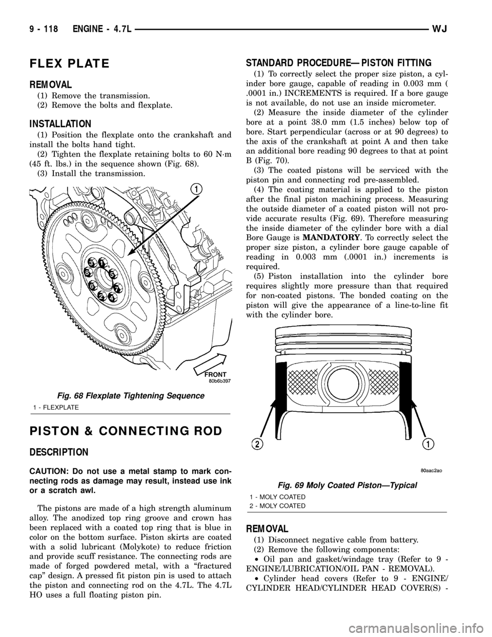
(2) Tighten the flexplate retaining bolts to 60 N´m
(45 ft. lbs.) in the sequence shown (Fig. 68).
(3) Install the transmission.
PISTON & CONNECTING ROD
DESCRIPTION
CAUTION: Do not use a metal stamp to mark con-
necting rods as damage may result, instead use ink
or a scratch awl.
The pistons are made of a high strength aluminum
alloy. The anodized top ring groove and crown has
been replaced with a coated top ring that is blue in
color on the bottom surface. Piston skirts are coated
with a solid lubricant (Molykote) to reduce friction
and provide scuff resistance. The connecting rods are
made of forged powdered metal, with a ªfractured
capº design. A pressed fit piston pin is used to attach
the piston and connecting rod on the 4.7L. The 4.7L
HO uses a full floating piston pin.
STANDARD PROCEDUREÐPISTON FITTING
(1) To correctly select the proper size piston, a cyl-
inder bore gauge, capable of reading in 0.003 mm (
.0001 in.) INCREMENTS is required. If a bore gauge
is not available, do not use an inside micrometer.
(2) Measure the inside diameter of the cylinder
bore at a point 38.0 mm (1.5 inches) below top of
bore. Start perpendicular (across or at 90 degrees) to
the axis of the crankshaft at point A and then take
an additional bore reading 90 degrees to that at point
B (Fig. 70).
(3) The coated pistons will be serviced with the
piston pin and connecting rod pre-assembled.
(4) The coating material is applied to the piston
after the final piston machining process. Measuring
the outside diameter of a coated piston will not pro-
vide accurate results (Fig. 69). Therefore measuring
the inside diameter of the cylinder bore with a dial
Bore Gauge isMANDATORY. To correctly select the
proper size piston, a cylinder bore gauge capable of
reading in 0.003 mm (.0001 in.) increments is
required.
(5) Piston installation into the cylinder bore
requires slightly more pressure than that required
for non-coated pistons. The bonded coating on the
piston will give the appearance of a line-to-line fit
with the cylinder bore.
REMOVAL
(1) Disconnect negative cable from battery.
(2) Remove the following components:
²Oil pan and gasket/windage tray (Refer to 9 -
ENGINE/LUBRICATION/OIL PAN - REMOVAL).
²Cylinder head covers (Refer to 9 - ENGINE/
CYLINDER HEAD/CYLINDER HEAD COVER(S) -
Fig. 68 Flexplate Tightening Sequence
1 - FLEXPLATE
Fig. 69 Moly Coated PistonÐTypical
1 - MOLY COATED
2 - MOLY COATED
9 - 118 ENGINE - 4.7LWJ
Page 1372 of 2199
(5) If the leak is not detected, very slowly turn the
crankshaft and watch for leakage. If a leak is
detected between the crankshaft and seal while
slowly turning the crankshaft, it is possible the
crankshaft seal surface is damaged. The seal area on
the crankshaft could have minor nicks or scratches
that can be polished out with emery cloth.
CAUTION: Use extreme caution when crankshaft
polishing is necessary to remove minor nicks or
scratches. The crankshaft seal flange is specially
machined to complement the function of the rear oil
seal.
(6) For bubbles that remain steady with shaft
rotation, no further inspection can be done until dis-
assembled. (Refer to 9 - ENGINE - DIAGNOSIS AND
TESTING), under the Oil Leak row, for components
inspections on possible causes and corrections.
(7) After the oil leak root cause and appropriate
corrective action have been identified, (Refer to 9 -
ENGINE/ENGINE BLOCK/CRANKSHAFT OIL
SEAL - REAR - REMOVAL).
DIAGNOSIS AND TESTINGÐENGINE OIL LEAK
Begin with a thorough visual inspection of the
engine, particularly at the area of the suspected leak.If an oil leak source is not readily identifiable, the
following steps should be followed:
(1) Do not clean or degrease the engine at this
time because some solvents may cause rubber to
swell, temporarily stopping the leak.
(2) Add an oil soluble dye (use as recommended by
manufacturer). Start the engine and let idle for
approximately 15 minutes. Check the oil dipstick to
make sure the dye is thoroughly mixed as indicated
with a bright yellow color under a black light.
(3) Using a black light, inspect the entire engine
for fluorescent dye, particularly at the suspected area
of oil leak. If the oil leak is found and identified,
repair per service manual instructions.
(4) If dye is not observed, drive the vehicle at var-
ious speeds for approximately 24km (15 miles), and
repeat inspection.If the oil leak source is not pos-
itively identified at this time, proceed with the air
leak detection test method.
Air Leak Detection Test Method
(1) Disconnect the breather cap to air cleaner hose
at the breather cap end. Cap or plug breather cap
nipple.
(2) Remove the PCV valve from the cylinder head
cover. Cap or plug the PCV valve grommet.
(3) Attach an air hose with pressure gauge and
regulator to the dipstick tube.
CAUTION: Do not subject the engine assembly to
more than 20.6 kpa (3 PSI) of test pressure.
(4) Gradually apply air pressure from 1 psi to 2.5
psi maximum while applying soapy water at the sus-
pected source. Adjust the regulator to the suitable
test pressure that provide the best bubbles which
will pinpoint the leak source. If the oil leak is
detected and identified, repair per service manual
procedures.
(5) If the leakage occurs at the rear oil seal area,
refer to the section, Inspection for Rear Seal Area
Leak.
(6) If no leaks are detected, turn off the air supply
and remove the air hose and all plugs and caps.
Install the PCV valve and breather cap hose.
(7) Clean the oil off the suspect oil leak area using
a suitable solvent. Drive the vehicle at various
speeds approximately 24 km (15 miles). Inspect the
engine for signs of an oil leak by using a black light.
INSPECTION FOR REAR SEAL AREA LEAKS
Since it is sometimes difficult to determine the
source of an oil leak in the rear seal area of the
engine, a more involved inspection is necessary. The
following steps should be followed to help pinpoint
the source of the leak.
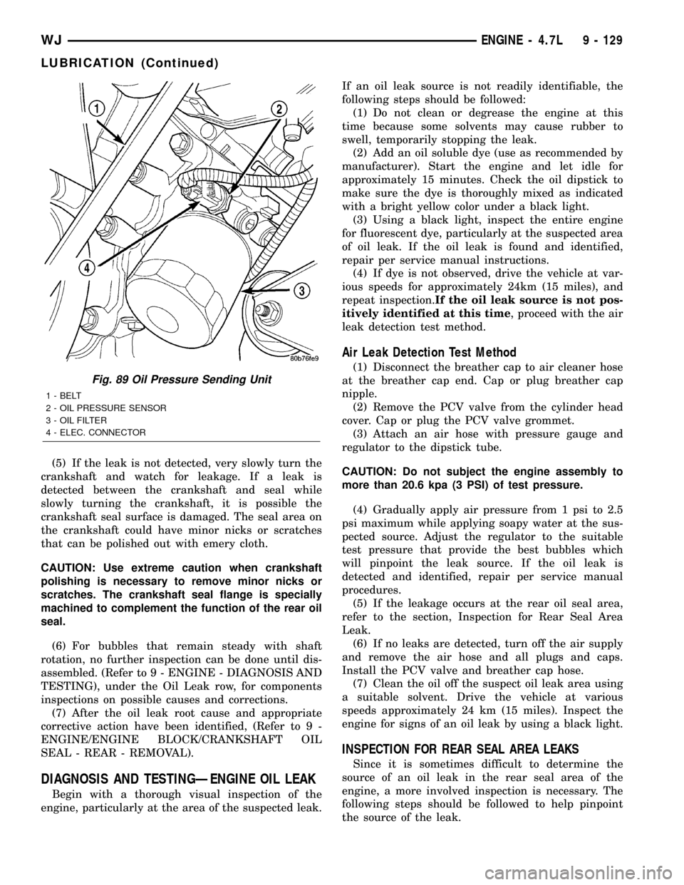
Fig. 89 Oil Pressure Sending Unit
1 - BELT
2 - OIL PRESSURE SENSOR
3 - OIL FILTER
4 - ELEC. CONNECTOR
WJENGINE - 4.7L 9 - 129
LUBRICATION (Continued)
Page 1435 of 2199
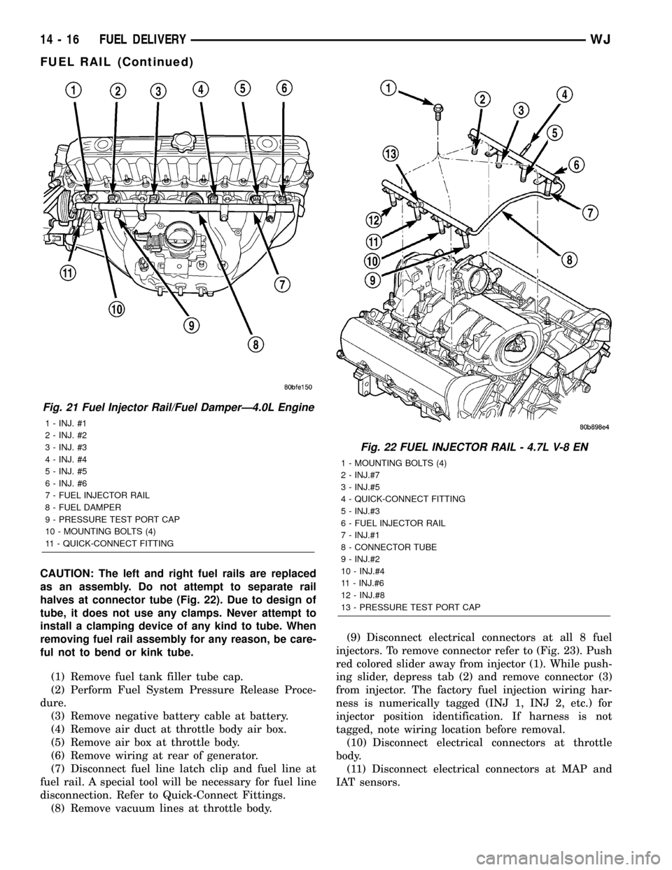
CAUTION: The left and right fuel rails are replaced
as an assembly. Do not attempt to separate rail
halves at connector tube (Fig. 22). Due to design of
tube, it does not use any clamps. Never attempt to
install a clamping device of any kind to tube. When
removing fuel rail assembly for any reason, be care-
ful not to bend or kink tube.
(1) Remove fuel tank filler tube cap.
(2) Perform Fuel System Pressure Release Proce-
dure.
(3) Remove negative battery cable at battery.
(4) Remove air duct at throttle body air box.
(5) Remove air box at throttle body.
(6) Remove wiring at rear of generator.
(7) Disconnect fuel line latch clip and fuel line at
fuel rail. A special tool will be necessary for fuel line
disconnection. Refer to Quick-Connect Fittings.
(8) Remove vacuum lines at throttle body.(9) Disconnect electrical connectors at all 8 fuel
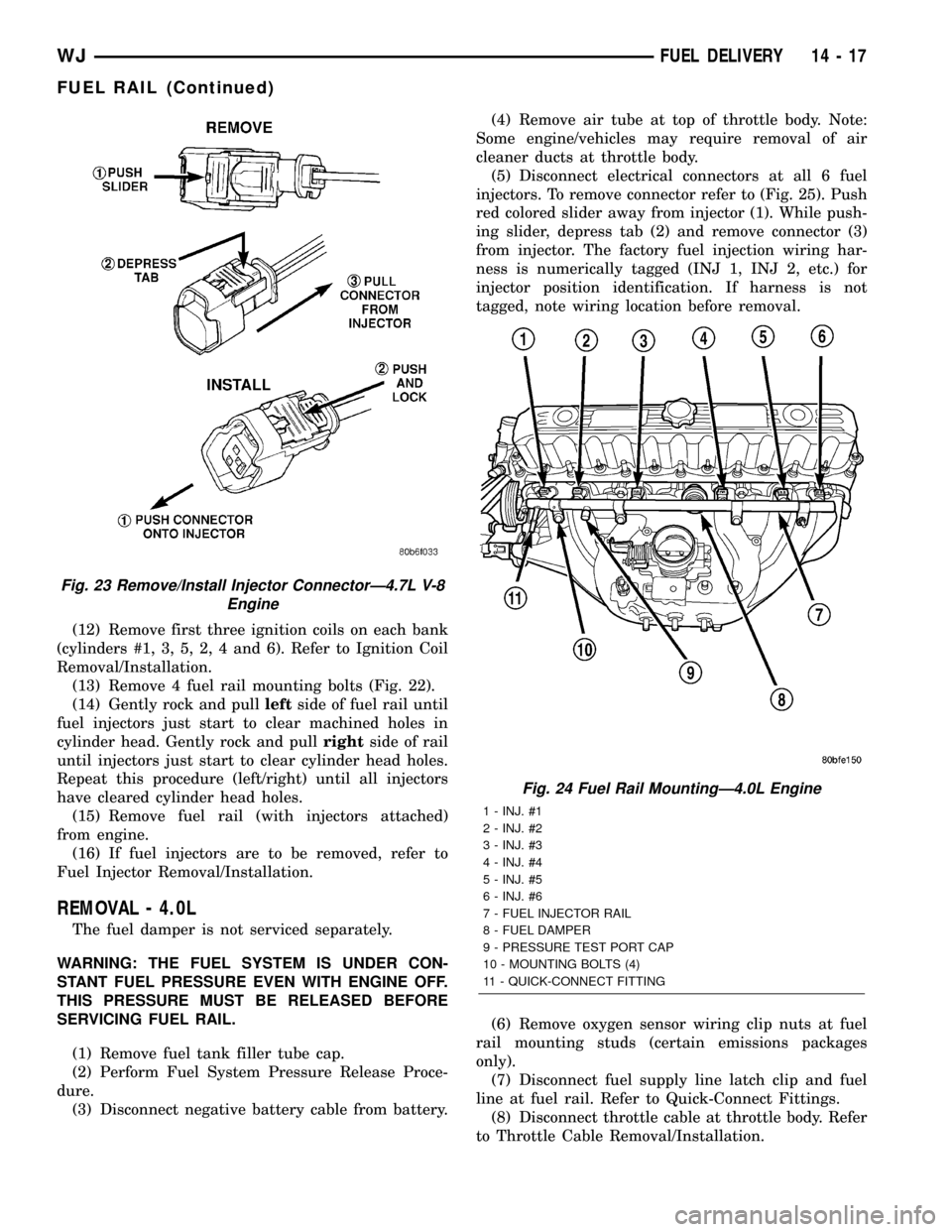
injectors. To remove connector refer to (Fig. 23). Push
red colored slider away from injector (1). While push-
ing slider, depress tab (2) and remove connector (3)
from injector. The factory fuel injection wiring har-
ness is numerically tagged (INJ 1, INJ 2, etc.) for
injector position identification. If harness is not
tagged, note wiring location before removal.
(10) Disconnect electrical connectors at throttle
body.
(11) Disconnect electrical connectors at MAP and
IAT sensors.
Fig. 21 Fuel Injector Rail/Fuel DamperÐ4.0L Engine
1 - INJ. #1
2 - INJ. #2
3 - INJ. #3
4 - INJ. #4
5 - INJ. #5
6 - INJ. #6
7 - FUEL INJECTOR RAIL
8 - FUEL DAMPER
9 - PRESSURE TEST PORT CAP
10 - MOUNTING BOLTS (4)
11 - QUICK-CONNECT FITTING
Fig. 22 FUEL INJECTOR RAIL - 4.7L V-8 EN
1 - MOUNTING BOLTS (4)
2 - INJ.#7
3 - INJ.#5
4 - QUICK-CONNECT FITTING
5 - INJ.#3
6 - FUEL INJECTOR RAIL
7 - INJ.#1
8 - CONNECTOR TUBE
9 - INJ.#2
10 - INJ.#4
11 - INJ.#6
12 - INJ.#8
13 - PRESSURE TEST PORT CAP
14 - 16 FUEL DELIVERYWJ
FUEL RAIL (Continued)
Page 1436 of 2199
(12) Remove first three ignition coils on each bank
(cylinders #1, 3, 5, 2, 4 and 6). Refer to Ignition Coil
Removal/Installation.
(13) Remove 4 fuel rail mounting bolts (Fig. 22).
(14) Gently rock and pullleftside of fuel rail until
fuel injectors just start to clear machined holes in
cylinder head. Gently rock and pullrightside of rail
until injectors just start to clear cylinder head holes.
Repeat this procedure (left/right) until all injectors
have cleared cylinder head holes.
(15) Remove fuel rail (with injectors attached)
from engine.
(16) If fuel injectors are to be removed, refer to
Fuel Injector Removal/Installation.
REMOVAL - 4.0L
The fuel damper is not serviced separately.
WARNING: THE FUEL SYSTEM IS UNDER CON-
STANT FUEL PRESSURE EVEN WITH ENGINE OFF.
THIS PRESSURE MUST BE RELEASED BEFORE
SERVICING FUEL RAIL.
(1) Remove fuel tank filler tube cap.
(2) Perform Fuel System Pressure Release Proce-
dure.
(3) Disconnect negative battery cable from battery.(4) Remove air tube at top of throttle body. Note:
Some engine/vehicles may require removal of air
cleaner ducts at throttle body.
(5) Disconnect electrical connectors at all 6 fuel
injectors. To remove connector refer to (Fig. 25). Push
red colored slider away from injector (1). While push-
ing slider, depress tab (2) and remove connector (3)
from injector. The factory fuel injection wiring har-
ness is numerically tagged (INJ 1, INJ 2, etc.) for
injector position identification. If harness is not
tagged, note wiring location before removal.
(6) Remove oxygen sensor wiring clip nuts at fuel
rail mounting studs (certain emissions packages
only).
(7) Disconnect fuel supply line latch clip and fuel
line at fuel rail. Refer to Quick-Connect Fittings.
(8) Disconnect throttle cable at throttle body. Refer
to Throttle Cable Removal/Installation.
Fig. 23 Remove/Install Injector ConnectorÐ4.7L V-8
Engine
Fig. 24 Fuel Rail MountingÐ4.0L Engine
1 - INJ. #1
2 - INJ. #2
3 - INJ. #3
4 - INJ. #4
5 - INJ. #5
6 - INJ. #6
7 - FUEL INJECTOR RAIL
8 - FUEL DAMPER
9 - PRESSURE TEST PORT CAP
10 - MOUNTING BOLTS (4)
11 - QUICK-CONNECT FITTING
WJFUEL DELIVERY 14 - 17
FUEL RAIL (Continued)
Page 1437 of 2199
(9) Disconnect speed control cable at throttle body
(if equipped). Refer to Speed Control Cable.
(10) Disconnect automatic transmission cable at
throttle body (if equipped).
(11) Remove cable routing bracket at intake mani-
fold.
(12) Clean dirt/debris from each fuel injector at
intake manifold.
(13) Remove fuel rail mounting nuts/bolts (Fig.
24).
(14) Remove fuel rail by gently rocking until all
fuel injectors have cleared machined holes at intake
manifold.
(15) If fuel injectors are to be removed, refer to
Fuel Injector Removal/Installation.
INSTALLATION
INSTALLATION - 4.7L
(1) If fuel injectors are to be installed, refer to Fuel
Injector Removal/Installation.
(2) Apply a small amount of engine oil to each fuel
injector o-ring. This will help in fuel rail installation.
(3) Position fuel rail/fuel injector assembly to
machined injector openings in cylinder head.
(4) Guide each injector into cylinder head. Be care-
ful not to tear injector o-rings.(5) Pushrightside of fuel rail down until fuel
injectors have bottomed on cylinder head shoulder.
Pushleftfuel rail down until injectors have bot-
tomed on cylinder head shoulder.
(6) Install 4 fuel rail mounting bolts and tighten to
27 N´m (20 ft. lbs.).
(7) Install ignition coils. Refer to Ignition Coil
Removal/Installation.
(8) Connect electrical connectors to throttle body.
(9) Connect electrical connectors to MAP and IAT
sensors.
(10) Connect electrical connectors at all fuel injec-
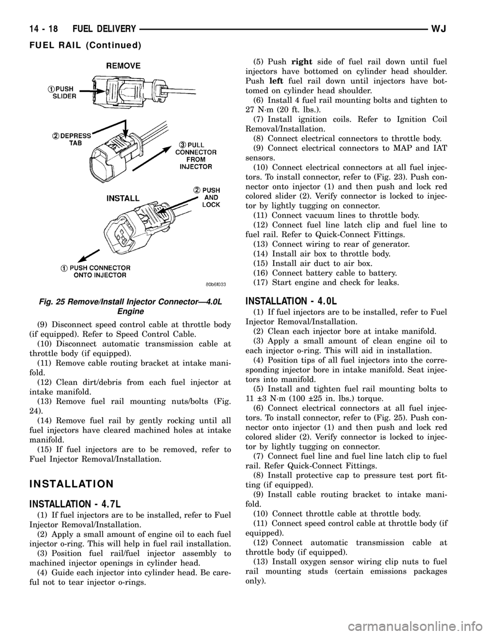
tors. To install connector, refer to (Fig. 23). Push con-
nector onto injector (1) and then push and lock red
colored slider (2). Verify connector is locked to injec-
tor by lightly tugging on connector.
(11) Connect vacuum lines to throttle body.
(12) Connect fuel line latch clip and fuel line to
fuel rail. Refer to Quick-Connect Fittings.
(13) Connect wiring to rear of generator.
(14) Install air box to throttle body.
(15) Install air duct to air box.
(16) Connect battery cable to battery.
(17) Start engine and check for leaks.
INSTALLATION - 4.0L
(1) If fuel injectors are to be installed, refer to Fuel
Injector Removal/Installation.
(2) Clean each injector bore at intake manifold.
(3) Apply a small amount of clean engine oil to
each injector o-ring. This will aid in installation.
(4) Position tips of all fuel injectors into the corre-
sponding injector bore in intake manifold. Seat injec-
tors into manifold.
(5) Install and tighten fuel rail mounting bolts to
11 3 N´m (100 25 in. lbs.) torque.
(6) Connect electrical connectors at all fuel injec-
tors. To install connector, refer to (Fig. 25). Push con-
nector onto injector (1) and then push and lock red
colored slider (2). Verify connector is locked to injec-
tor by lightly tugging on connector.
(7) Connect fuel line and fuel line latch clip to fuel
rail. Refer Quick-Connect Fittings.
(8) Install protective cap to pressure test port fit-
ting (if equipped).
(9) Install cable routing bracket to intake mani-
fold.
(10) Connect throttle cable at throttle body.
(11) Connect speed control cable at throttle body (if
equipped).
(12) Connect automatic transmission cable at
throttle body (if equipped).
(13) Install oxygen sensor wiring clip nuts to fuel
rail mounting studs (certain emissions packages
only).
Fig. 25 Remove/Install Injector ConnectorÐ4.0L
Engine
14 - 18 FUEL DELIVERYWJ
FUEL RAIL (Continued)
Page 1447 of 2199
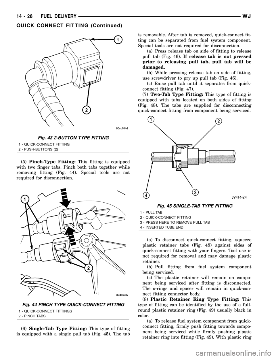
(5)Pinch-Type Fitting:This fitting is equipped
with two finger tabs. Pinch both tabs together while
removing fitting (Fig. 44). Special tools are not
required for disconnection.
(6)Single-Tab Type Fitting:This type of fitting
is equipped with a single pull tab (Fig. 45). The tabis removable. After tab is removed, quick-connect fit-
ting can be separated from fuel system component.
Special tools are not required for disconnection.
(a) Press release tab on side of fitting to release
pull tab (Fig. 46).If release tab is not pressed
prior to releasing pull tab, pull tab will be
damaged.
(b) While pressing release tab on side of fitting,
use screwdriver to pry up pull tab (Fig. 46).
(c) Raise pull tab until it separates from quick-
connect fitting (Fig. 47).
(7)Two-Tab Type Fitting:This type of fitting is
equipped with tabs located on both sides of fitting
(Fig. 48). The tabs are supplied for disconnecting
quick-connect fitting from component being serviced.
(a) To disconnect quick-connect fitting, squeeze
plastic retainer tabs (Fig. 48) against sides of
quick-connect fitting with your fingers. Tool use is
not required for removal and may damage plastic
retainer.
(b) Pull fitting from fuel system component
being serviced.
(c) The plastic retainer will remain on compo-
nent being serviced after fitting is disconnected.
The o-rings and spacer will remain in quick-con-
nect fitting connector body.
(8)Plastic Retainer Ring Type Fitting:This
type of fitting can be identified by the use of a full-
round plastic retainer ring (Fig. 49) usually black in
color.
(a) To release fuel system component from quick-
connect fitting, firmly push fitting towards compo-
nent being serviced while firmly pushing plastic
retainer ring into fitting (Fig. 49). With plastic ring
Fig. 43 2-BUTTON TYPE FITTING
1 - QUICK-CONNECT FITTING
2 - PUSH-BUTTONS (2)
Fig. 44 PINCH TYPE QUICK-CONNECT FITTING
1 - QUICK-CONNECT FITTINGS
2 - PINCH TABS
Fig. 45 SINGLE-TAB TYPE FITTING
1 - PULL TAB
2 - QUICK-CONNECT FITTING
3 - PRESS HERE TO REMOVE PULL TAB
4 - INSERTED TUBE END
14 - 28 FUEL DELIVERYWJ
QUICK CONNECT FITTING (Continued)
Page 1588 of 2199
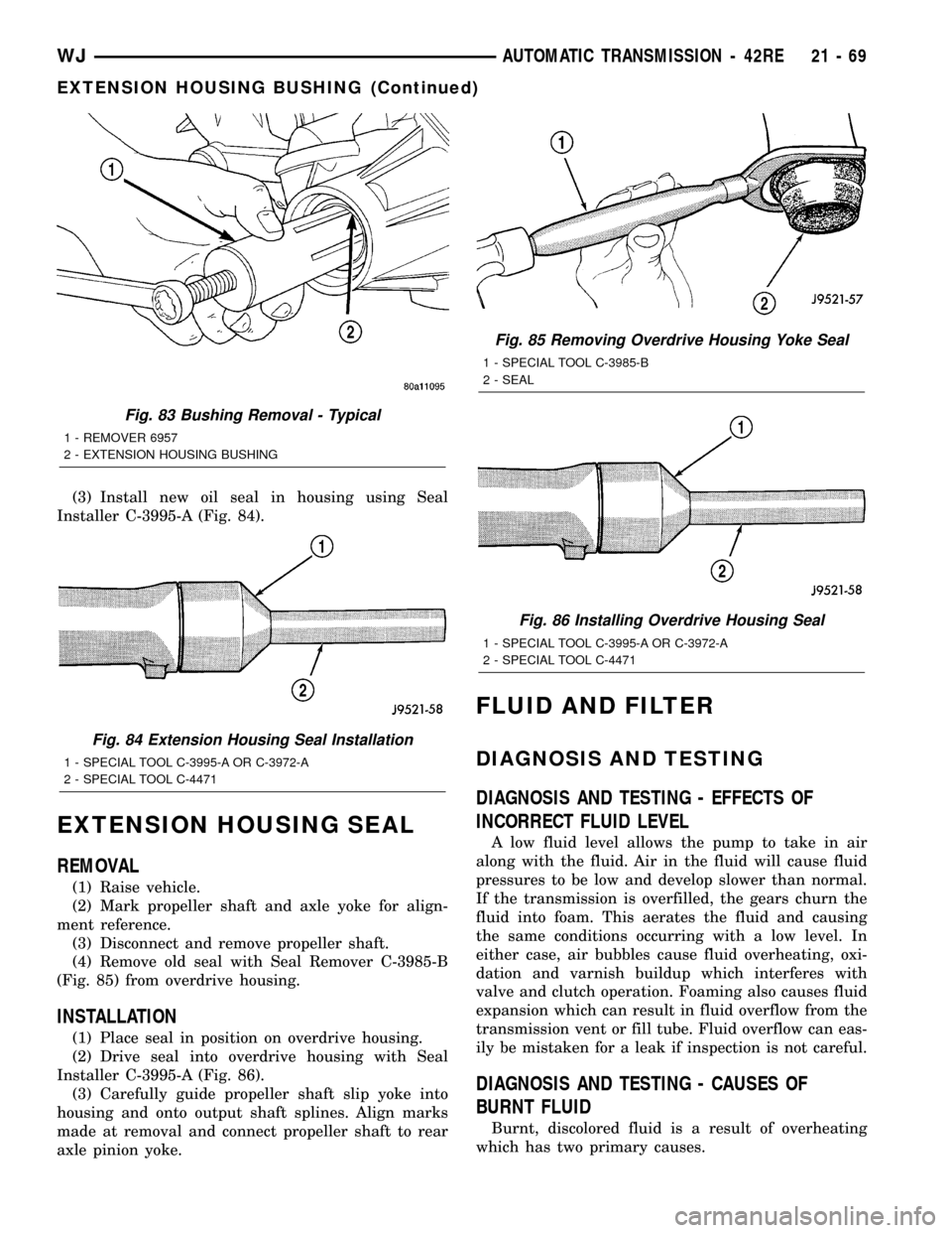
(3) Install new oil seal in housing using Seal
Installer C-3995-A (Fig. 84).
EXTENSION HOUSING SEAL
REMOVAL
(1) Raise vehicle.
(2) Mark propeller shaft and axle yoke for align-
ment reference.
(3) Disconnect and remove propeller shaft.
(4) Remove old seal with Seal Remover C-3985-B
(Fig. 85) from overdrive housing.
INSTALLATION
(1) Place seal in position on overdrive housing.
(2) Drive seal into overdrive housing with Seal
Installer C-3995-A (Fig. 86).
(3) Carefully guide propeller shaft slip yoke into
housing and onto output shaft splines. Align marks
made at removal and connect propeller shaft to rear
axle pinion yoke.
FLUID AND FILTER
DIAGNOSIS AND TESTING
DIAGNOSIS AND TESTING - EFFECTS OF
INCORRECT FLUID LEVEL
A low fluid level allows the pump to take in air
along with the fluid. Air in the fluid will cause fluid
pressures to be low and develop slower than normal.
If the transmission is overfilled, the gears churn the
fluid into foam. This aerates the fluid and causing
the same conditions occurring with a low level. In
either case, air bubbles cause fluid overheating, oxi-
dation and varnish buildup which interferes with
valve and clutch operation. Foaming also causes fluid
expansion which can result in fluid overflow from the
transmission vent or fill tube. Fluid overflow can eas-
ily be mistaken for a leak if inspection is not careful.
DIAGNOSIS AND TESTING - CAUSES OF
BURNT FLUID
Burnt, discolored fluid is a result of overheating
which has two primary causes.
Fig. 83 Bushing Removal - Typical
1 - REMOVER 6957
2 - EXTENSION HOUSING BUSHING
Fig. 84 Extension Housing Seal Installation
1 - SPECIAL TOOL C-3995-A OR C-3972-A
2 - SPECIAL TOOL C-4471
Fig. 85 Removing Overdrive Housing Yoke Seal
1 - SPECIAL TOOL C-3985-B
2 - SEAL
Fig. 86 Installing Overdrive Housing Seal
1 - SPECIAL TOOL C-3995-A OR C-3972-A
2 - SPECIAL TOOL C-4471
WJAUTOMATIC TRANSMISSION - 42RE 21 - 69
EXTENSION HOUSING BUSHING (Continued)