2002 JEEP GRAND CHEROKEE Auto start
[x] Cancel search: Auto startPage 1123 of 2199
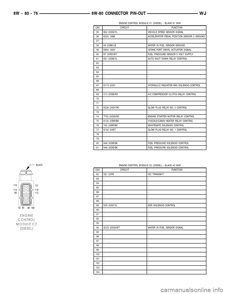
ENGINE CONTROL MODULE C1 (DIESEL) - BLACK 81 WAY
CAV CIRCUIT FUNCTION
55 B22 20DG/YL VEHICLE SPEED SENSOR SIGNAL
56 K225 18BK ACCELERATOR PEDAL POSITION SENSOR 2 GROUND
57 - -
58 K4 20BK/LB WATER IN FUEL SENSOR GROUND
59 K900 18GY INTAKE PORT SWIRL ACTUATOR SIGNAL
60 K7 20RD/WT FUEL PRESSURE SENSOR 5 VOLT SUPPLY
61 K51 20DB/YL AUTO SHUT DOWN RELAY CONTROL
62 - -
63 - -
64 - -
65 - -
66 - -
67 K173 20GY HYDRAULIC RADIATOR FAN SOLENOID CONTROL
68 - -
69 C13 20DB/RD A/C COMPRESSOR CLUTCH RELAY CONTROL
70 - -
71 - -
72 K236 20GY/PK GLOW PLUG RELAY NO. 2 CONTROL
73 - -
74 T752 20DG/RD ENGINE STARTER MOTOR RELAY CONTROL
75 K132 20BR/BK VISCOUS/CABIN HEATER RELAY CONTROL
76 Y42 20BR/BK WASTEGATE SOLENOID CONTROL
77 K152 20WT GLOW PLUG RELAY NO. 1 CONTROL
78 - -
79 - -
80 K46 20DB/BK FUEL PRESSURE SOLENOID CONTROL
81 K46 20DB/BK FUEL PRESSURE SOLENOID CONTROL
ENGINE CONTROL MODULE C2 (DIESEL) - BLACK 40 WAY
CAV CIRCUIT FUNCTION
82 D21 20PK SCI TRANSMIT
83 - -
84 - -
85 - -
86 - -
87 - -
88 - -
89 K35 20GY/YL EGR SOLENOID CONTROL
90 - -
91 - -
92 - -
93 - -
94 G123 20DG/WT WATER IN FUEL SENSOR SIGNAL
95 - -
96 - -
97 - -
98 - -
99 - -
100 - -
101 - -
102 - -
103 - -
104 - -
8W - 80 - 76 8W-80 CONNECTOR PIN-OUTWJ
Page 1131 of 2199
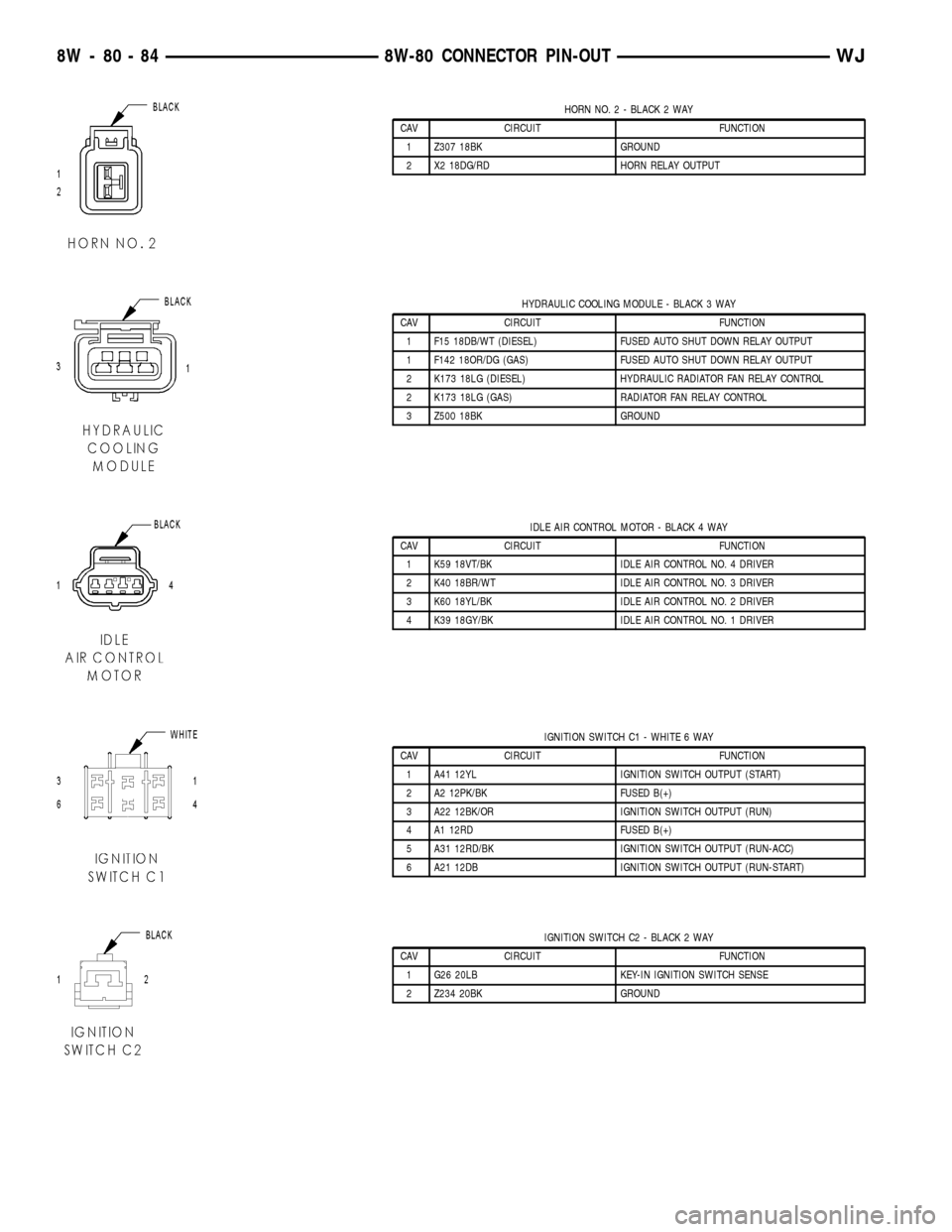
HORN NO. 2 - BLACK 2 WAY
CAV CIRCUIT FUNCTION
1 Z307 18BK GROUND
2 X2 18DG/RD HORN RELAY OUTPUT
HYDRAULIC COOLING MODULE - BLACK 3 WAY
CAV CIRCUIT FUNCTION
1 F15 18DB/WT (DIESEL) FUSED AUTO SHUT DOWN RELAY OUTPUT
1 F142 18OR/DG (GAS) FUSED AUTO SHUT DOWN RELAY OUTPUT
2 K173 18LG (DIESEL) HYDRAULIC RADIATOR FAN RELAY CONTROL
2 K173 18LG (GAS) RADIATOR FAN RELAY CONTROL
3 Z500 18BK GROUND
IDLE AIR CONTROL MOTOR - BLACK 4 WAY
CAV CIRCUIT FUNCTION
1 K59 18VT/BK IDLE AIR CONTROL NO. 4 DRIVER
2 K40 18BR/WT IDLE AIR CONTROL NO. 3 DRIVER
3 K60 18YL/BK IDLE AIR CONTROL NO. 2 DRIVER
4 K39 18GY/BK IDLE AIR CONTROL NO. 1 DRIVER
IGNITION SWITCH C1 - WHITE 6 WAY
CAV CIRCUIT FUNCTION
1 A41 12YL IGNITION SWITCH OUTPUT (START)
2 A2 12PK/BK FUSED B(+)
3 A22 12BK/OR IGNITION SWITCH OUTPUT (RUN)
4 A1 12RD FUSED B(+)
5 A31 12RD/BK IGNITION SWITCH OUTPUT (RUN-ACC)
6 A21 12DB IGNITION SWITCH OUTPUT (RUN-START)
IGNITION SWITCH C2 - BLACK 2 WAY
CAV CIRCUIT FUNCTION
1 G26 20LB KEY-IN IGNITION SWITCH SENSE
2 Z234 20BK GROUND
8W - 80 - 84 8W-80 CONNECTOR PIN-OUTWJ
Page 1133 of 2199
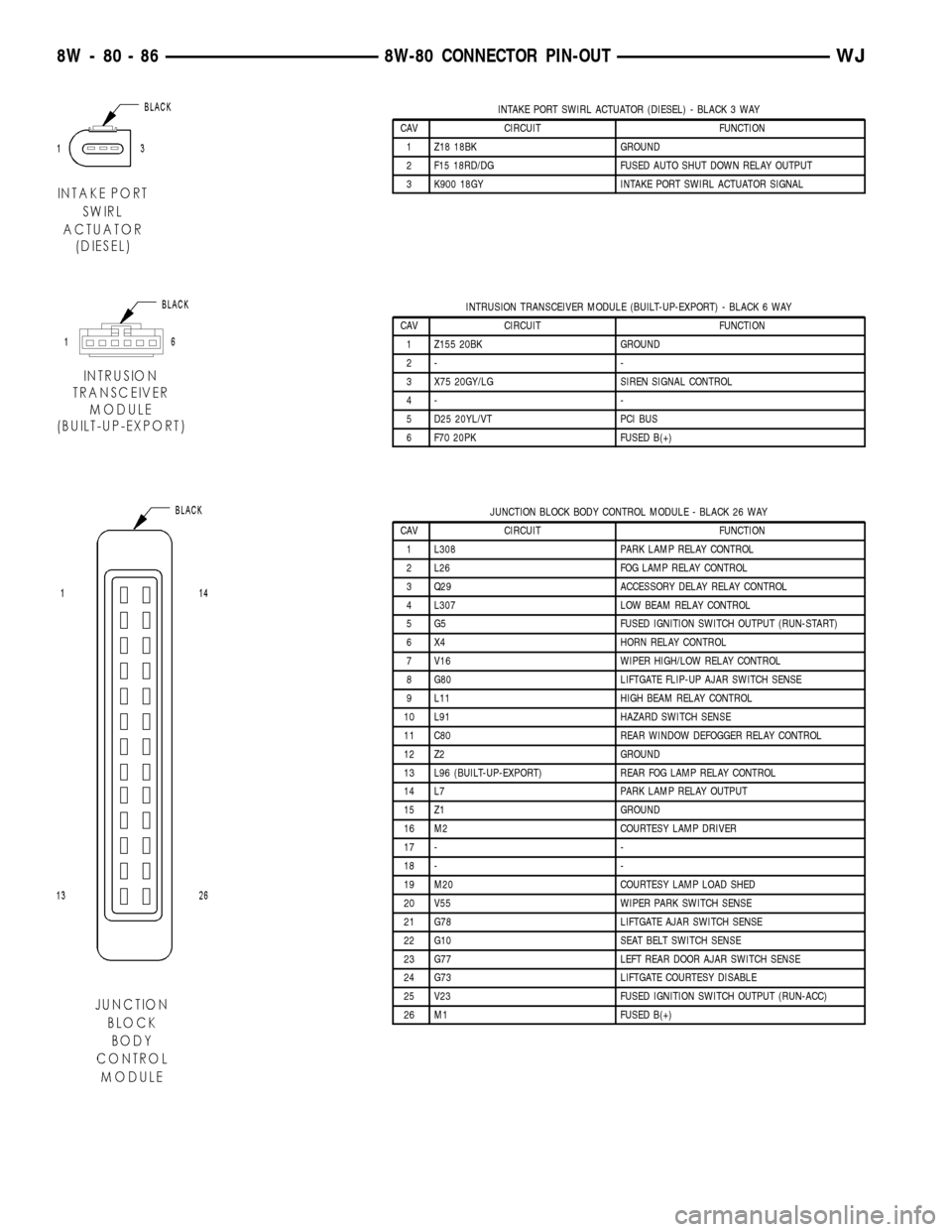
INTAKE PORT SWIRL ACTUATOR (DIESEL) - BLACK 3 WAY
CAV CIRCUIT FUNCTION
1 Z18 18BK GROUND
2 F15 18RD/DG FUSED AUTO SHUT DOWN RELAY OUTPUT
3 K900 18GY INTAKE PORT SWIRL ACTUATOR SIGNAL
INTRUSION TRANSCEIVER MODULE (BUILT-UP-EXPORT) - BLACK 6 WAY
CAV CIRCUIT FUNCTION
1 Z155 20BK GROUND
2- -
3 X75 20GY/LG SIREN SIGNAL CONTROL
4- -
5 D25 20YL/VT PCI BUS
6 F70 20PK FUSED B(+)
JUNCTION BLOCK BODY CONTROL MODULE - BLACK 26 WAY
CAV CIRCUIT FUNCTION
1 L308 PARK LAMP RELAY CONTROL
2 L26 FOG LAMP RELAY CONTROL
3 Q29 ACCESSORY DELAY RELAY CONTROL
4 L307 LOW BEAM RELAY CONTROL
5 G5 FUSED IGNITION SWITCH OUTPUT (RUN-START)
6 X4 HORN RELAY CONTROL
7 V16 WIPER HIGH/LOW RELAY CONTROL
8 G80 LIFTGATE FLIP-UP AJAR SWITCH SENSE
9 L11 HIGH BEAM RELAY CONTROL
10 L91 HAZARD SWITCH SENSE
11 C80 REAR WINDOW DEFOGGER RELAY CONTROL
12 Z2 GROUND
13 L96 (BUILT-UP-EXPORT) REAR FOG LAMP RELAY CONTROL
14 L7 PARK LAMP RELAY OUTPUT
15 Z1 GROUND
16 M2 COURTESY LAMP DRIVER
17 - -
18 - -
19 M20 COURTESY LAMP LOAD SHED
20 V55 WIPER PARK SWITCH SENSE
21 G78 LIFTGATE AJAR SWITCH SENSE
22 G10 SEAT BELT SWITCH SENSE
23 G77 LEFT REAR DOOR AJAR SWITCH SENSE
24 G73 LIFTGATE COURTESY DISABLE
25 V23 FUSED IGNITION SWITCH OUTPUT (RUN-ACC)
26 M1 FUSED B(+)
8W - 80 - 86 8W-80 CONNECTOR PIN-OUTWJ
Page 1174 of 2199
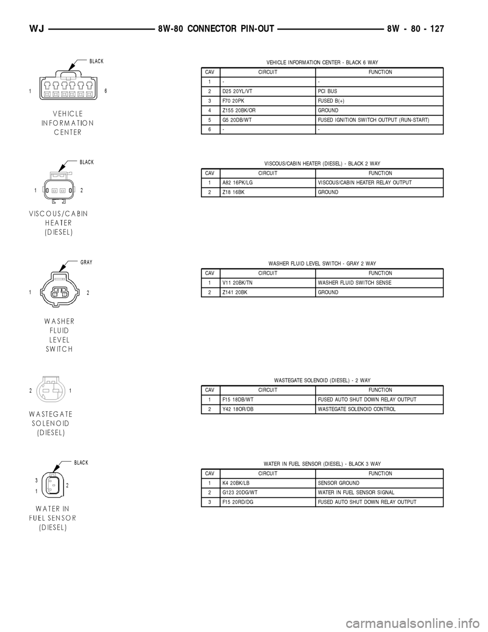
VEHICLE INFORMATION CENTER - BLACK 6 WAY
CAV CIRCUIT FUNCTION
1- -
2 D25 20YL/VT PCI BUS
3 F70 20PK FUSED B(+)
4 Z155 20BK/OR GROUND
5 G5 20DB/WT FUSED IGNITION SWITCH OUTPUT (RUN-START)
6- -
VISCOUS/CABIN HEATER (DIESEL) - BLACK 2 WAY
CAV CIRCUIT FUNCTION
1 A82 16PK/LG VISCOUS/CABIN HEATER RELAY OUTPUT
2 Z18 16BK GROUND
WASHER FLUID LEVEL SWITCH - GRAY 2 WAY
CAV CIRCUIT FUNCTION
1 V11 20BK/TN WASHER FLUID SWITCH SENSE
2 Z141 20BK GROUND
WASTEGATE SOLENOID (DIESEL)-2WAY
CAV CIRCUIT FUNCTION
1 F15 18DB/WT FUSED AUTO SHUT DOWN RELAY OUTPUT
2 Y42 18OR/DB WASTEGATE SOLENOID CONTROL
WATER IN FUEL SENSOR (DIESEL) - BLACK 3 WAY
CAV CIRCUIT FUNCTION
1 K4 20BK/LB SENSOR GROUND
2 G123 20DG/WT WATER IN FUEL SENSOR SIGNAL
3 F15 20RD/DG FUSED AUTO SHUT DOWN RELAY OUTPUT
WJ8W-80 CONNECTOR PIN-OUT 8W - 80 - 127
Page 1255 of 2199

(7) Remove the fan assembly from the water pump
(Refer to 7 - COOLING/ENGINE/RADIATOR FAN -
REMOVAL).
(8) Remove the fan shroud.
(9) Disconnect the transmission fluid cooler lines
(automatic transmission).
(10) Discharge the A/C system (Refer to 24 -
HEATING & AIR CONDITIONING/PLUMBING -
STANDARD PROCEDURE).
(11) Remove the service valves and cap the com-
pressor ports.
(12) Remove the radiator or radiator/condenser (if
equipped with A/C).
(13) Disconnect the heater hoses at the engine
thermostat housing and water pump.
(14) Disconnect the accelerator cable, transmission
line pressure cable and speed control cable (if
equipped) from the throttle body.
(15) Remove cables from the bracket and secure
out of the way.
(16) Disconnect the body ground at the engine.
(17) Disconnect the following connectors and
secure their harness out of the way.
²Power steering pressure switch
²Coolant temperature sensor
²Six (6) fuel injector connectors
²Intake air temperature sensor
²Throttle position sensor
²Map sensor
²Crankshaft position sensor
²Oxygen sensor
²Camshaft position sensor
²Generator connector and B+ terminal wire
(18) Disconnect the coil rail electrical connections
and the oil pressure switch connector.
(19) Perform the fuel pressure release procedure
(Refer to 14 - FUEL SYSTEM/FUEL DELIVERY -
STANDARD PROCEDURE).
(20) Disconnect the fuel supply line at the injector
rail (Refer to 14 - FUEL SYSTEM/FUEL DELIVERY/
QUICK CONNECT FITTING - STANDARD PROCE-
DURE).
(21) Remove the fuel line bracket from the intake
manifold.
(22) Remove the air cleaner assembly (Fig. 5).
(23) Disconnect the hoses from the fittings at the
steering gear.
(24) Drain the pump reservoir.
(25) Cap the fittings on the hoses and steering
gear to prevent foreign objects from entering the sys-
tem.
(26) Raise and support the vehicle.
(27) Disconnect the wires from the engine starter
motor solenoid.(28) Remove the engine starter motor (Refer to 8 -
ELECTRICAL/STARTING/STARTER MOTOR -
REMOVAL).
(29) Disconnect the oxygen sensor from the
exhaust pipe.
(30) Disconnect the exhaust pipe from the mani-
fold.
(31) Remove the exhaust pipe support.
(32) Remove the bending brace (Refer to 9 -
ENGINE/ENGINE BLOCK/STRUCT SUPPORT -
REMOVAL).
(33) Remove the engine flywheel/converter housing
access cover.
(34) Mark the converter and drive plate location.
(35) Remove the converter-to-drive plate bolts.
(36) Remove the upper engine flywheel/converter
housing bolts and loosen the bottom bolts.
(37) Remove the engine mount cushion-to-engine
compartment bracket bolts.
(38) Lower the vehicle.
(39) Attach a lifting device to the engine.
(40) Raise the engine off the front supports.
(41) Place a support or floor jack under the con-
verter (or engine flywheel) housing.
(42) Remove the remaining converter (or engine
flywheel) housing bolts.
(43) Lift the engine out of the engine compart-
ment.
Fig. 5 Air Cleaner Assembly
1 - POWER STEERING PUMP
2 - AIR CLEANER ASSEMBLY
9 - 12 ENGINE - 4.0LWJ
ENGINE - 4.0L (Continued)
Page 1256 of 2199

INSTALLATION
CAUTION: When installing the engine into a vehicle
equipped with an automatic transmission, be care-
ful not to damage the trigger wheel on the engine
flywheel.
(1) Attach a lifting device to the engine and lower
the engine into the engine compartment. For easier
installation, it may be necessary to remove the
engine mount bracket as an aid in alignment of the
engine to the transmission.
(2) Align the transmission torque converter hous-
ing with the engine.
(3) Loosely install the converter housing lower
bolts and install the next higher bolt and nut on each
side.
(4) Tighten all 4 bolts finger tight.
(5) Install the engine mount brackets (if removed).
(6) Lower the engine and engine mount brackets
onto the engine compartment cushions. Install the
bolts and finger tighten the nuts.
(7) Remove the engine lifting device.
(8) Raise and support the vehicle.
(9) Install the remaining engine flywheel/converter
housing bolts. Tighten all bolts to 38 N´m (28 ft. lbs.)
torque.
(10) Install the converter-to-drive plate bolts.
(11) Ensure the installation reference marks are
aligned.
(12) Install the engine flywheel/converter housing
access cover.
(13) Install the exhaust pipe support and tighten
the screw.
(14) Install the engine bending brace (Refer to 9 -
ENGINE/ENGINE BLOCK/STRUCT SUPPORT -
INSTALLATION).
(15) Tighten the engine mount-to-bracket bolts.
(16) Connect the vehicle speed sensor wire connec-
tions and tighten the screws.
(17) Connect the exhaust pipe to the manifold.
(18) Install the engine starter motor (Refer to 8 -
ELECTRICAL/STARTING/STARTER MOTOR -
INSTALLATION).
(19) Connect the wires to the engine starter motor
solenoid.
(20) Lower the vehicle.
(21) Connect all the vacuum hoses and wire con-
nectors identified during engine removal.
(22) Remove protective caps from the power steer-
ing hoses.
(23) Connect the hoses to the fittings at the steer-
ing gear. Tighten the nut to 52 N´m (38 ft. lbs.)
torque.
(24) Fill the pump reservoir with fluid.(25) Inspect the fuel supply line o-ring(s) and
replace if necessary. Connect fuel supply line to injec-
tior rail and verify connection by pulling outward on
the line.
(26) Install the fuel line bracket to the intake
manifold.
(27) Connect the coil rail electrical connectors and
oil pressure switch connector.
(28) Connect the following electrical connectors:
²Power steering pressure switch
²Coolant temperature sensor
²Six (6) fuel injector connectors
²Intake air temperature sensor
²Throttle position sensor
²Map sensor
²Crankshaft position sensor
²Oxygen sensor
²Camshaft position sensor
²Generator connector and B+ terminal wire
(29) Connect all previously removed vacuum hoses.
(30) Connect the body ground strap.
(31) Install the throttle, transmission line pres-
sure, and speed control cables to their mounting
bracket and connect them to the throttle body.
(32) Connect the heater hoses at the engine ther-
mostat housing and water pump.
(33) Install the fan assembly (Refer to 7 - COOL-
ING/ENGINE/RADIATOR FAN - INSTALLATION).
(34) Place the fan shroud in position over the fan.
(35) Install the radiator (Refer to 7 - COOLING/
ENGINE/RADIATOR - INSTALLATION).
(36) Connect the service valves to the A/C com-
pressor ports, if equipped with A/C.
(37) Charge the air conditioner system (Refer to 24
- HEATING & AIR CONDITIONING/PLUMBING -
STANDARD PROCEDURE).
(38) Connect the radiator hoses and automatic
transmission fluid cooler pipes, if equipped.
(39) Install the fan shroud to the radiator or radi-
ator/condenser (if equipped with A/C).
(40) Install upper radiator support.
(41) Connect the upper radiator hose and tighten
the clamp.
(42) Connect the lower radiator hose and tighten
the clamp.
(43) Fill crankcase with engine oil. (Refer to
LUBRICATION & MAINTENANCE/FLUID CAPACI-
TIES - SPECIFICATIONS) for correct capacities.
(44) Fill the cooling system with reusable coolant
or new coolant (Refer to 7 - COOLING - STANDARD
PROCEDURE).
(45) Align the hood to the scribe marks. Install the
hood.
(46) Install the air cleaner assembly.
(47) Install the battery and connect the battery
cable.
WJENGINE - 4.0L 9 - 13
ENGINE - 4.0L (Continued)
Page 1261 of 2199
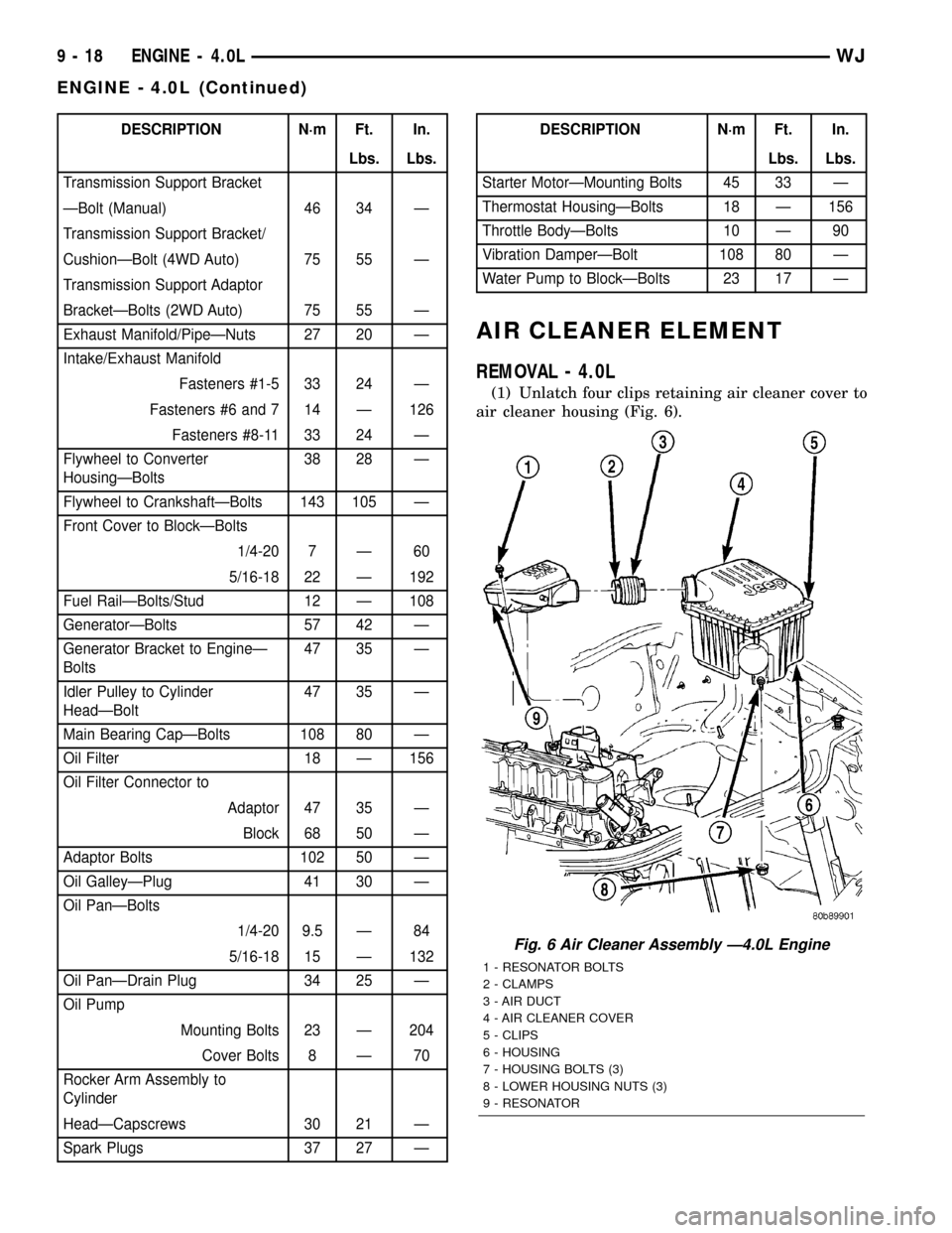
DESCRIPTION N´m Ft. In.
Lbs. Lbs.
Transmission Support Bracket
ÐBolt (Manual) 46 34 Ð
Transmission Support Bracket/
CushionÐBolt (4WD Auto) 75 55 Ð
Transmission Support Adaptor
BracketÐBolts (2WD Auto) 75 55 Ð
Exhaust Manifold/PipeÐNuts 27 20 Ð
Intake/Exhaust Manifold
Fasteners #1-5 33 24 Ð
Fasteners #6 and 7 14 Ð 126
Fasteners #8-11 33 24 Ð
Flywheel to Converter
HousingÐBolts38 28 Ð
Flywheel to CrankshaftÐBolts 143 105 Ð
Front Cover to BlockÐBolts
1/4-20 7 Ð 60
5/16-18 22 Ð 192
Fuel RailÐBolts/Stud 12 Ð 108
GeneratorÐBolts 57 42 Ð
Generator Bracket to EngineÐ
Bolts47 35 Ð
Idler Pulley to Cylinder
HeadÐBolt47 35 Ð
Main Bearing CapÐBolts 108 80 Ð
Oil Filter 18 Ð 156
Oil Filter Connector to
Adaptor 47 35 Ð
Block 68 50 Ð
Adaptor Bolts 102 50 Ð
Oil GalleyÐPlug 41 30 Ð
Oil PanÐBolts
1/4-20 9.5 Ð 84
5/16-18 15 Ð 132
Oil PanÐDrain Plug 34 25 Ð
Oil Pump
Mounting Bolts 23 Ð 204
Cover Bolts 8 Ð 70
Rocker Arm Assembly to
Cylinder
HeadÐCapscrews 30 21 Ð
Spark Plugs 37 27 ÐDESCRIPTION N´m Ft. In.
Lbs. Lbs.
Starter MotorÐMounting Bolts 45 33 Ð
Thermostat HousingÐBolts 18 Ð 156
Throttle BodyÐBolts 10 Ð 90
Vibration DamperÐBolt 108 80 Ð
Water Pump to BlockÐBolts 23 17 Ð
AIR CLEANER ELEMENT
REMOVAL - 4.0L
(1) Unlatch four clips retaining air cleaner cover to
air cleaner housing (Fig. 6).
Fig. 6 Air Cleaner Assembly Ð4.0L Engine
1 - RESONATOR BOLTS
2 - CLAMPS
3 - AIR DUCT
4 - AIR CLEANER COVER
5 - CLIPS
6 - HOUSING
7 - HOUSING BOLTS (3)
8 - LOWER HOUSING NUTS (3)
9 - RESONATOR
9 - 18 ENGINE - 4.0LWJ
ENGINE - 4.0L (Continued)
Page 1300 of 2199

INSTALLATION
A gear-type oil pump is mounted at the underside
of the cylinder block opposite the No.4 main bearing.
(1) Install the oil pump on the cylinder block using
a replacement gasket. Tighten the bolts to 23 N´m
(17 ft. lbs.) torque.
(2) Install the oil pan (Refer to 9 - ENGINE/LU-
BRICATION/OIL PAN - INSTALLATION).
(3) Fill the oil pan with oil to the specified level.
INTAKE MANIFOLD
DESCRIPTION
The intake manifold (Fig. 83) is made of cast alu-
minum and uses eleven bolts to mount to the cylin-
der head. This mounting style improves sealing and
reduces the chance of leaks.
DIAGNOSIS AND TESTING - INTAKE
MANIFOLD LEAKAGE
An intake manifold air leak is characterized by
lower than normal manifold vacuum. Also, one or
more cylinders may not be functioning.
WARNING: USE EXTREME CAUTION WHEN THE
ENGINE IS OPERATING. DO NOT STAND IN A
DIRECT LINE WITH THE FAN. DO NOT PUT YOUR
HANDS NEAR THE PULLEYS, BELTS OR THE FAN.
DO NOT WEAR LOOSE CLOTHING.
(1) Start the engine.
(2) Spray a small stream of water at the suspected
leak area.
(3) If a change in RPM is observed the area of the
suspected leak has been found.
(4) Repair as required.
REMOVAL
NOTE: THE ENGINE INTAKE AND EXHAUST MANI-
FOLD MUST BE REMOVED AND INSTALLED
TOGETHER. THE MANIFOLDS USE A COMMON
GASKET AT THE CYLINDER HEAD.
(1) Disconnect the battery negative cable.
(2) Remove air cleaner inlet hose from the resona-
tor assembly.
(3) Remove the air cleaner assembly.
(4) Remove the throttle cable, vehicle speed control
cable (if equipped) and the transmission line pres-
sure cable (Refer to 21 - TRANSMISSION/TRANS-
AXLE/AUTOMATIC - AW4/THROTTLE VALVE
CABLE - REMOVAL).
(5) Disconnect the following electrical connections
and secure their harness out of the way:
²Throttle Position Sensor
²Idle Air Control Motor
²Coolant Temperature Sensor (at thermostat
housing)
²Intake Air Temperature Sensor
²Oxygen Sensor
²Crank Position Sensor
²Six (6) Fuel Injector Connectors
²Manifold Absolute Pressure (MAP) Sensor.
(6) Disconnect HVAC, and Brake Booster vacuum
supply hoses at the intake manifold.
(7) Perform the fuel pressure release procedure.
(Refer to 14 - FUEL SYSTEM/FUEL DELIVERY -
STANDARD PROCEDURE).
(8) Disconnect and remove the fuel system supply
line from the fuel rail assembly.
(9) Remove the accessory drive belt (Refer to 7 -
COOLING/ACCESSORY DRIVE/DRIVE BELTS -
REMOVAL).
(10) Remove the power steering pump from the
intake manifold and set aside.
(11) Raise the vehicle.
(12) Disconnect the exhaust pipes from the engine
exhaust manifolds.
(13) Lower the vehicle.
(14) Remove the intake manifold and exhaust
manifold bolts and manifolds (Fig. 84).
INSTALLATION
If the manifold is being replaced, ensure all the fit-
ting, etc. are transferred to the replacement mani-
fold.
(1) Install a new engine exhaust/intake manifold
gasket over the alignment dowels on the cylinder
head.
(2) Position the engine exhaust manifolds to the
cylinder head. Install fastener Number 3 and finger
tighten at this time (Fig. 84).
Fig. 83 Intake Manifold 4.0L Engine
WJENGINE - 4.0L 9 - 57
OIL PUMP (Continued)