2002 JEEP GRAND CHEROKEE fuel line
[x] Cancel search: fuel linePage 1421 of 2199
FUEL DELIVERY
DESCRIPTION
The fuel delivery system consists of:
²the fuel pump module containing the electric
fuel pump, fuel gauge sending unit (fuel level sensor)
and a separate fuel filter located at bottom of pump
module
²a separate combination fuel filter/fuel pressure
regulator
²fuel tubes/lines/hoses
²quick-connect fittings
²fuel injector rail
²fuel injectors
²fuel tank
²fuel tank filler/vent tube assembly
²fuel tank filler tube cap
²accelerator pedal
²throttle cable
OPERATION
The fuel tank assembly consists of: the fuel tank,
fuel tank shield, fuel tank straps, fuel pump module
assembly, fuel pump module locknut/gasket, and fuel
tank check valve (refer to Emission Control System
for fuel tank check valve information).
A fuel filler/vent tube assembly using a pressure/
vacuum, 1/4 turn fuel filler cap is used. The fuel
filler tube contains a flap door located below the fuel
fill cap.
Also to be considered part of the fuel system is the
evaporation control system. This is designed to
reduce the emission of fuel vapors into the atmo-
sphere. The description and function of the Evapora-
tive Control System is found in Emission Control
Systems.
Both fuel filters (at bottom of fuel pump module
and within fuel pressure regulator) are designed for
extended service. They do not require normal sched-
uled maintenance. Filters should only be replaced if
a diagnostic procedure indicates to do so.
DIAGNOSIS AND TESTING
FUEL PRESSURE LEAK DOWN TEST
Use this test in conjunction with the Fuel Pump
Pressure Test and Fuel Pump Capacity Test.
Check Valve Operation:The electric fuel pump
outlet contains a one-way check valve to prevent fuel
flow back into the tank and to maintain fuel supply
line pressure (engine warm) when pump is not oper-
ational. It is also used to keep the fuel supply line
full of gasoline when pump is not operational. After
the vehicle has cooled down, fuel pressure may drop
to 0 psi (cold fluid contracts), but liquid gasoline willremain in fuel supply line between the check valve
and fuel injectors.Fuel pressure that has
dropped to 0 psi on a cooled down vehicle
(engine off) is a normal condition.When the elec-
tric fuel pump is activated, fuel pressure should
immediately(1±2 seconds) rise to specification.
Abnormally long periods of cranking to restart a
hotengine that has been shut down for a short
period of time may be caused by:
²Fuel pressure bleeding past a fuel injector(s).
²Fuel pressure bleeding past the check valve in
the fuel pump module.
²A defective fuel filter/pressure regulator.
Two #6539, 5/16º, Fuel Line Pressure Test Adapter
Hose Tools are required for the following tests.
(1) Release fuel system pressure. Refer to Fuel
Pressure Release Procedure.
(2) Raise vehicle.
Fuel Line Identification:The fuel filter/pressure
regulator is located in front of the fuel tank and
above the rear axle. It is transversely mounted to a
chassis crossmember (left-to-right). The filter/regula-
tor is equipped with 3 fuel line fittings (2 at one end
and 1 at the other end). The single fitting facing the
left side of the vehicle is the supply line to the fuel
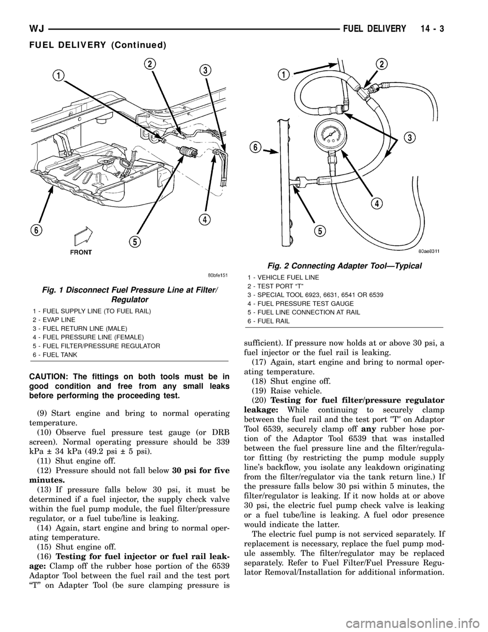
rail (Fig. 1) . The 2 fittings facing the right side of
the vehicle are connected to the fuel tank. Of these 2
fittings, the fitting towards thefrontis used for fuel
return to the fuel tank. The fitting towards therear
is a pressure line. Thisrearfitting must be discon-
nected for the following step.
(3) See previous step. Disconnect fuel pressure line
atrearof filter/regulator. This is a 5/169quick-con-
nect fitting (Fig. 1) . Refer to Quick-Connect Fittings
for procedures.
(4) Obtain correct Fuel Line Pressure Test Adapter
Hose Tool # 6539 for 5/16º fuel lines. Connect one
end of this Special Tool into the disconnected fuel
pressure line. Connect the other end of the Tool into
fitting on filter/regulator.
(5) Lower vehicle.
(6) Disconnect the fuel inlet line at fuel rail. Refer
to Quick-Connect Fittings for procedures. On some
engines, air cleaner housing removal may be neces-
sary before fuel line disconnection.
(7) Obtain a second Fuel Line Pressure Test
Adapter Hose Tool # 6539 for 5/16º fuel lines. Con-
nect this tool between disconnected fuel line and fuel
rail (Fig. 2) .
(8) Connect the 0-414 kPa (0-60 psi) fuel pressure
test gauge (from Gauge Set 5069) to the test port on
the appropriate Adaptor Tool.NOTE: The DRB III
Scan Tool along with the PEP module, the 500
psi pressure transducer, and the transducer-to-
test port adapter may also be used in place of
the fuel pressure gauge.
14 - 2 FUEL DELIVERYWJ
Page 1422 of 2199
CAUTION: The fittings on both tools must be in
good condition and free from any small leaks
before performing the proceeding test.
(9) Start engine and bring to normal operating
temperature.
(10) Observe fuel pressure test gauge (or DRB
screen). Normal operating pressure should be 339
kPa 34 kPa (49.2 psi 5 psi).
(11) Shut engine off.
(12) Pressure should not fall below30 psi for five
minutes.
(13) If pressure falls below 30 psi, it must be
determined if a fuel injector, the supply check valve
within the fuel pump module, the fuel filter/pressure
regulator, or a fuel tube/line is leaking.
(14) Again, start engine and bring to normal oper-
ating temperature.
(15) Shut engine off.
(16)Testing for fuel injector or fuel rail leak-
age:Clamp off the rubber hose portion of the 6539
Adaptor Tool between the fuel rail and the test port
ªTº on Adapter Tool (be sure clamping pressure issufficient). If pressure now holds at or above 30 psi, a
fuel injector or the fuel rail is leaking.
(17) Again, start engine and bring to normal oper-
ating temperature.
(18) Shut engine off.
(19) Raise vehicle.
(20)Testing for fuel filter/pressure regulator
leakage:While continuing to securely clamp
between the fuel rail and the test port9T9on Adaptor
Tool 6539, securely clamp offanyrubber hose por-
tion of the Adaptor Tool 6539 that was installed
between the fuel pressure line and the filter/regula-
tor fitting (by restricting the pump module supply
line's backflow, you isolate any leakdown originating
from the filter/regulator via the tank return line.) If
the pressure falls below 30 psi within 5 minutes, the
filter/regulator is leaking. If it now holds at or above
30 psi, the electric fuel pump check valve is leaking
or a fuel tube/line is leaking. A fuel odor presence
would indicate the latter.
The electric fuel pump is not serviced separately. If
replacement is necessary, replace the fuel pump mod-
ule assembly. The filter/regulator may be replaced
separately. Refer to Fuel Filter/Fuel Pressure Regu-
lator Removal/Installation for additional information.
Fig. 1 Disconnect Fuel Pressure Line at Filter/
Regulator
1 - FUEL SUPPLY LINE (TO FUEL RAIL)
2 - EVAP LINE
3 - FUEL RETURN LINE (MALE)
4 - FUEL PRESSURE LINE (FEMALE)
5 - FUEL FILTER/PRESSURE REGULATOR
6 - FUEL TANK
Fig. 2 Connecting Adapter ToolÐTypical
1 - VEHICLE FUEL LINE
2 - TEST PORT ªTº
3 - SPECIAL TOOL 6923, 6631, 6541 OR 6539
4 - FUEL PRESSURE TEST GAUGE
5 - FUEL LINE CONNECTION AT RAIL
6 - FUEL RAIL
WJFUEL DELIVERY 14 - 3
FUEL DELIVERY (Continued)
Page 1423 of 2199
STANDARD PROCEDURE - FUEL SYSTEM
PRESSURE RELEASE
Use following procedure if the fuel injector
rail is, or is not equipped with a fuel pressure
test port.
(1) Remove fuel fill cap.
(2) Remove fuel pump relay from Power Distribu-
tion Center (PDC). For location of relay, refer to label
on underside of PDC cover.
(3) Start and run engine until it stalls.
(4) Attempt restarting engine until it will no
longer run.
(5) Turn ignition key to OFF position.
CAUTION: Steps 1, 2, 3 and 4 must be performed to
relieve high pressure fuel from within fuel rail. Do
not attempt to use following steps to relieve this
pressure as excessive fuel will be forced into a cyl-
inder chamber.
(6) Unplug connector from any fuel injector.
(7) Attach one end of a jumper wire with alligator
clips (18 gauge or smaller) to either injector terminal.(8) Connect other end of jumper wire to positive
side of battery.
(9) Connect one end of a second jumper wire to
remaining injector terminal.
CAUTION: Powering an injector for more than a few
seconds will permanently damage the injector.
(10) Momentarily touch other end of jumper wire
to negative terminal of battery for no more than a
few seconds.
(11) Place a rag or towel below fuel line quick-con-
nect fitting at fuel rail.
(12) Disconnect quick-connect fitting at fuel rail.
Refer to Quick-Connect Fittings.
(13) Return fuel pump relay to PDC.
(14) One or more Diagnostic Trouble Codes (DTC's)
may have been stored in PCM memory due to fuel
pump relay removal. The DRBtscan tool must be
used to erase a DTC.
SPECIFICATIONS
FUEL SYSTEM PRESSURE
339 kPa 34 kPa (49.2 psi 5 psi).
TORQUE - FUEL DELIVERY
DESCRIPTION N-m Ft. Lbs. In. Lbs.
Accelerator Pedal Bracket Mounting Nuts
(without adjustable pedals)12 2 - 105 20
Fuel Filter/Fuel Press. Reg. Bolts 3 - 26
Fuel Hose Clamps 3 - 26
Fuel Injector Rail Mounting Bolts -4.0L Engine 11 - 100
Fuel Injector Rail Mounting Bolts -4.7L V-8
Engine11 - 100
Fuel Pump Module Locknut 74 55 -
Fuel Tank Filler Tube-to-Body Mounting Bolts 2 - 15
Fuel Tank-to-Body Mounting Bolts 88 65 -
Fuel Tank Support Bracket Bolts (large brackets) 88 65 -
Fuel Tank Support Bracket Bolts (small bracket) 5 - 45
Fuel Tank Support Bracket Nuts (large brackets) 61 45 -
Fuel Tank Heat Shield Nuts (shield-to-tank) 9 - 85
Fuel Tank Heat Shield Nuts (shield-to-body) 3 - 25
14 - 4 FUEL DELIVERYWJ
FUEL DELIVERY (Continued)
Page 1424 of 2199
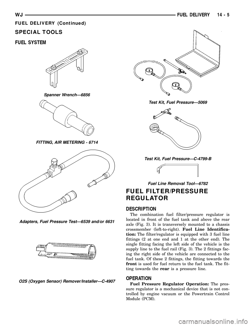
SPECIAL TOOLS
FUEL SYSTEM
FUEL FILTER/PRESSURE
REGULATOR
DESCRIPTION
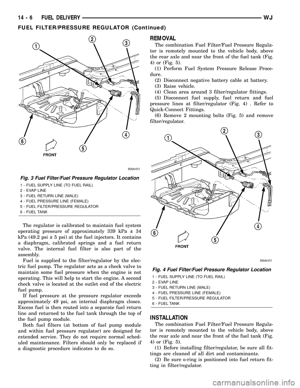
The combination fuel filter/pressure regulator is
located in front of the fuel tank and above the rear
axle (Fig. 3). It is transversely mounted to a chassis
crossmember (left-to-right).Fuel Line Identifica-
tion:The filter/regulator is equipped with 3 fuel line
fittings (2 at one end and 1 at the other end). The
single fitting facing the left side of the vehicle is the
supply line to the fuel rail (Fig. 3). The 2 fittings fac-
ing the right side of the vehicle are connected to the
fuel tank. Of these 2 fittings, the fitting towards the
frontis used for fuel return to the fuel tank. The fit-
ting towards therearis a pressure line.
OPERATION
Fuel Pressure Regulator Operation:The pres-
sure regulator is a mechanical device that is not con-
trolled by engine vacuum or the Powertrain Control
Module (PCM).
Spanner WrenchÐ6856
FITTING, AIR METERING - 6714
Adapters, Fuel Pressure TestÐ6539 and/or 6631
O2S (Oxygen Sensor) Remover/InstallerÐC-4907
Test Kit, Fuel PressureÐ5069
Test Kit, Fuel PressureÐC-4799-B
Fuel Line Removal ToolÐ6782
WJFUEL DELIVERY 14 - 5
FUEL DELIVERY (Continued)
Page 1425 of 2199
The regulator is calibrated to maintain fuel system
operating pressure of approximately 339 kPa 34
kPa (49.2 psi 5 psi) at the fuel injectors. It contains
a diaphragm, calibrated springs and a fuel return
valve. The internal fuel filter is also part of the
assembly.
Fuel is supplied to the filter/regulator by the elec-
tric fuel pump. The regulator acts as a check valve to
maintain some fuel pressure when the engine is not
operating. This will help to start the engine. A second
check valve is located at the outlet end of the electric
fuel pump.
If fuel pressure at the pressure regulator exceeds
approximately 49 psi, an internal diaphragm closes.
Excess fuel is then routed into a separate fuel return
line and returned to the fuel tank through the top of
the fuel pump module.
Both fuel filters (at bottom of fuel pump module
and within fuel pressure regulator) are designed for
extended service. They do not require normal sched-
uled maintenance. Filters should only be replaced if
a diagnostic procedure indicates to do so.
REMOVAL
The combination Fuel Filter/Fuel Pressure Regula-
tor is remotely mounted to the vehicle body, above
the rear axle and near the front of the fuel tank (Fig.
4) or (Fig. 5).
(1) Perform Fuel System Pressure Release Proce-
dure.
(2) Disconnect negative battery cable at battery.
(3) Raise vehicle.
(4) Clean area around 3 filter/regulator fittings.
(5) Disconnect fuel supply, fuel return and fuel
pressure lines at filter/regulator (Fig. 4) . Refer to
Quick-Connect Fittings.
(6) Remove 2 mounting bolts (Fig. 5) and remove
filter/regulator.
INSTALLATION
The combination Fuel Filter/Fuel Pressure Regula-
tor is remotely mounted to the vehicle body, above
the rear axle and near the front of the fuel tank (Fig.
4) or (Fig. 5).
(1) Before installing filter/regulator, be sure all fit-
tings are cleaned of all dirt and contaminants.
(2) Be sure o-ring is positioned into fuel return fit-
ting in filter/regulator.
Fig. 3 Fuel Filter/Fuel Pressure Regulator Location
1 - FUEL SUPPLY LINE (TO FUEL RAIL)
2 - EVAP LINE
3 - FUEL RETURN LINE (MALE)
4 - FUEL PRESSURE LINE (FEMALE)
5 - FUEL FILTER/PRESSURE REGULATOR
6 - FUEL TANK
Fig. 4 Fuel Filter/Fuel Pressure Regulator Location
1 - FUEL SUPPLY LINE (TO FUEL RAIL)
2 - EVAP LINE
3 - FUEL RETURN LINE (MALE)
4 - FUEL PRESSURE LINE (FEMALE)
5 - FUEL FILTER/PRESSURE REGULATOR
6 - FUEL TANK
14 - 6 FUEL DELIVERYWJ
FUEL FILTER/PRESSURE REGULATOR (Continued)
Page 1427 of 2199
(1) Remove fuel tank. Refer to Fuel Tank Removal/
Installation.(2) Remove fuel pump module. Refer to Fuel Pump
Module Removal/Installation.
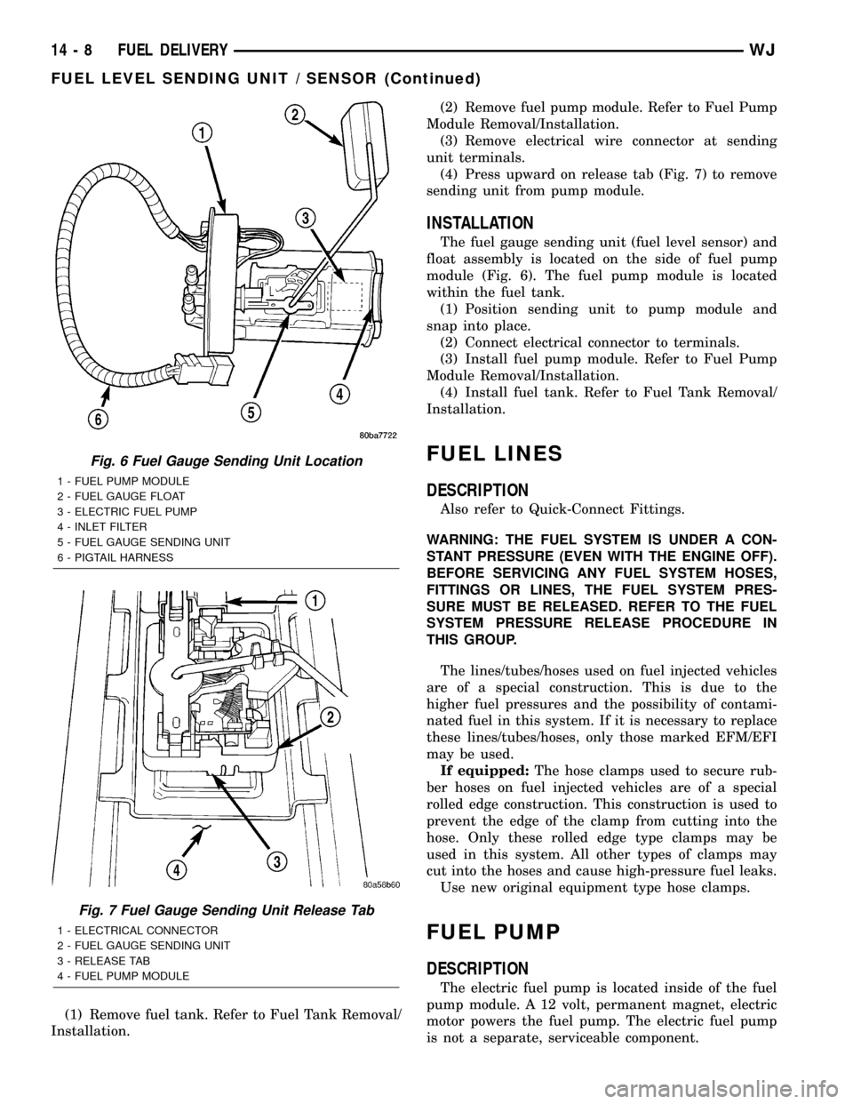
(3) Remove electrical wire connector at sending
unit terminals.
(4) Press upward on release tab (Fig. 7) to remove
sending unit from pump module.
INSTALLATION
The fuel gauge sending unit (fuel level sensor) and
float assembly is located on the side of fuel pump
module (Fig. 6). The fuel pump module is located
within the fuel tank.
(1) Position sending unit to pump module and
snap into place.
(2) Connect electrical connector to terminals.
(3) Install fuel pump module. Refer to Fuel Pump
Module Removal/Installation.
(4) Install fuel tank. Refer to Fuel Tank Removal/
Installation.
FUEL LINES
DESCRIPTION
Also refer to Quick-Connect Fittings.
WARNING: THE FUEL SYSTEM IS UNDER A CON-
STANT PRESSURE (EVEN WITH THE ENGINE OFF).
BEFORE SERVICING ANY FUEL SYSTEM HOSES,
FITTINGS OR LINES, THE FUEL SYSTEM PRES-
SURE MUST BE RELEASED. REFER TO THE FUEL
SYSTEM PRESSURE RELEASE PROCEDURE IN
THIS GROUP.
The lines/tubes/hoses used on fuel injected vehicles
are of a special construction. This is due to the
higher fuel pressures and the possibility of contami-
nated fuel in this system. If it is necessary to replace
these lines/tubes/hoses, only those marked EFM/EFI
may be used.
If equipped:The hose clamps used to secure rub-
ber hoses on fuel injected vehicles are of a special
rolled edge construction. This construction is used to
prevent the edge of the clamp from cutting into the
hose. Only these rolled edge type clamps may be
used in this system. All other types of clamps may
cut into the hoses and cause high-pressure fuel leaks.
Use new original equipment type hose clamps.
FUEL PUMP
DESCRIPTION
The electric fuel pump is located inside of the fuel
pump module. A 12 volt, permanent magnet, electric
motor powers the fuel pump. The electric fuel pump
is not a separate, serviceable component.
Fig. 6 Fuel Gauge Sending Unit Location
1 - FUEL PUMP MODULE
2 - FUEL GAUGE FLOAT
3 - ELECTRIC FUEL PUMP
4 - INLET FILTER
5 - FUEL GAUGE SENDING UNIT
6 - PIGTAIL HARNESS
Fig. 7 Fuel Gauge Sending Unit Release Tab
1 - ELECTRICAL CONNECTOR
2 - FUEL GAUGE SENDING UNIT
3 - RELEASE TAB
4 - FUEL PUMP MODULE
14 - 8 FUEL DELIVERYWJ
FUEL LEVEL SENDING UNIT / SENSOR (Continued)
Page 1428 of 2199
OPERATION
Voltage to operate the electric pump is supplied
through the fuel pump relay.
Fuel is drawn in through a filter at the bottom of
the module and pushed through the electric motor
gearset to the pump outlet.
Check Valve Operation:The pump outlet con-
tains a one-way check valve to prevent fuel flow back
into the tank and to maintain fuel supply line pres-
sure (engine warm) when pump is not operational. It
is also used to keep the fuel supply line full of gaso-
line when pump is not operational. After the vehicle
has cooled down, fuel pressure may drop to 0 psi
(cold fluid contracts), but liquid gasoline will remain
in fuel supply line between the check valve and fuel
injectors.Fuel pressure that has dropped to 0
psi on a cooled down vehicle (engine off) is a
normal condition.Refer to the Fuel Pressure Leak
Down Test for more information.
The electric fuel pump is not a separate, service-
able component.
DIAGNOSIS AND TESTING
DIAGNOSIS AND TESTING - FUEL PUMP
CAPACITY TEST
Before performing this test, verify fuel pump
pressure. Refer to Fuel Pump Pressure Test.
Use this test in conjunction with the Fuel Pres-
sure Leak Down Test.
(1) Release fuel system pressure. Refer to Fuel
Pressure Release Procedure.
(2) Disconnect fuel supply line at fuel rail. Refer to
Quick-Connect Fittings. Some engines may require
air cleaner housing removal before line disconnection.
(3) Obtain correct Fuel Line Pressure Test Adapter
Tool Hose. Tool number 6539 is used for 5/16º fuel
lines and tool number 6631 is used for 3/8º fuel lines.
(4) Connect correct Fuel Line Pressure Test
Adapter Tool Hose into disconnected fuel supply line.
Insert other end of Adaptor Tool Hose into a gradu-
ated container.
(5) Remove fuel fill cap.
(6) To activate fuel pump and pressurize system,
obtain DRBtscan tool and actuate ASD Fuel System
Test.
(7) A good fuel pump will deliver at least 1/4 liter
of fuel in 7 seconds. Do not operate fuel pump for
longer than 7 seconds with fuel line disconnected as
fuel pump module reservoir may run empty.
(a) If capacity is lower than specification, but
fuel pump can be heard operating through fuel fill
cap opening, check for a kinked/damaged fuel sup-
ply line somewhere between fuel rail and fuel
pump module.(b) If line is not kinked/damaged, and fuel pres-
sure is OK, but capacity is low, replace fuel filter/
fuel pressure regulator. The filter/regulator may be
serviced separately on certain applications. Refer
to Fuel Filter/Fuel Pressure Regulator Removal/In-
stallation for additional information.
(c) If both fuel pressure and capacity are low,
replace fuel pump module assembly. Refer to Fuel
Pump Module Removal/Installation.
DIAGNOSIS AND TESTING - FUEL PUMP
AMPERAGE TEST
This amperage (current draw) test is to be done in
conjunction with the Fuel Pump Pressure Test, Fuel
Pump Capacity Test and Fuel Pressure Leak Down
Test. Before performing the amperage test, be sure
the temperature of the fuel tank is above 50É F (10É
C).
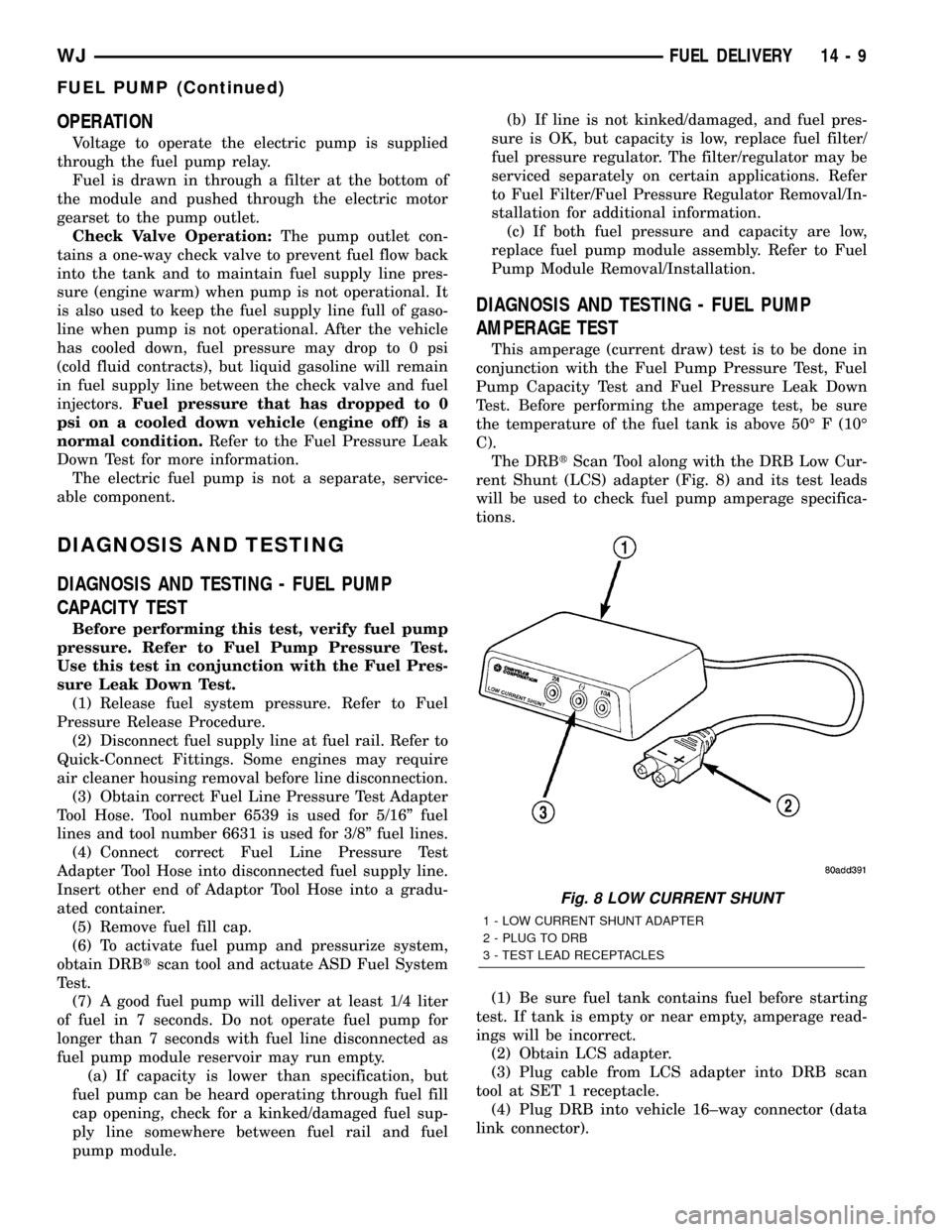
The DRBtScan Tool along with the DRB Low Cur-
rent Shunt (LCS) adapter (Fig. 8) and its test leads
will be used to check fuel pump amperage specifica-
tions.
(1) Be sure fuel tank contains fuel before starting
test. If tank is empty or near empty, amperage read-
ings will be incorrect.
(2) Obtain LCS adapter.
(3) Plug cable from LCS adapter into DRB scan
tool at SET 1 receptacle.
(4) Plug DRB into vehicle 16±way connector (data
link connector).
Fig. 8 LOW CURRENT SHUNT
1 - LOW CURRENT SHUNT ADAPTER
2 - PLUG TO DRB
3 - TEST LEAD RECEPTACLES
WJFUEL DELIVERY 14 - 9
FUEL PUMP (Continued)
Page 1429 of 2199
(5) Connect (-) and (+) test cable leads into LCS
adapter receptacles. Use10 amp (10A +)receptacle
and common (-) receptacles.
(6) Gain access to MAIN MENU on DRB screen.
(7) Press DVOM button on DRB.
(8) Using left/right arrow keys, highlight CHAN-
NEL 1 function on DRB screen.
(9) Press ENTER three times.
(10) Using up/down arrow keys, highlight RANGE
on DRB screen (screen will default to 2 amp scale).
(11) Press ENTER to change 2 amp scale to 10
amp scale.This step must be done to prevent
damage to DRB scan tool or LCS adapter
(blown fuse).
(12) Remove cover from Power Distribution Center
(PDC).
(13) Remove fuel pump relay from PDC. Refer to
label on PDC cover for relay location.
WARNING: BEFORE PROCEEDING TO NEXT STEP,
NOTE THE FUEL PUMP WILL BE ACTIVATED AND
SYSTEM PRESSURE WILL BE PRESENT. THIS WILL
OCCUR AFTER CONNECTING TEST LEADS FROM
LCS ADAPTER INTO FUEL PUMP RELAY CAVITIES.
THE FUEL PUMP WILL OPERATE EVEN WITH IGNI-
TION KEY IN OFF POSITION. BEFORE ATTACHING
TEST LEADS, BE SURE ALL FUEL LINES AND
FUEL SYSTEM COMPONENTS ARE CONNECTED.
CAUTION: To prevent possible damage to the vehi-
cle electrical system and LCS adapter, the test
leads must be connected into relay cavities exactly
as shown in following steps.
Depending upon vehicle model, year or engine con-
figuration, three different types of relays may be
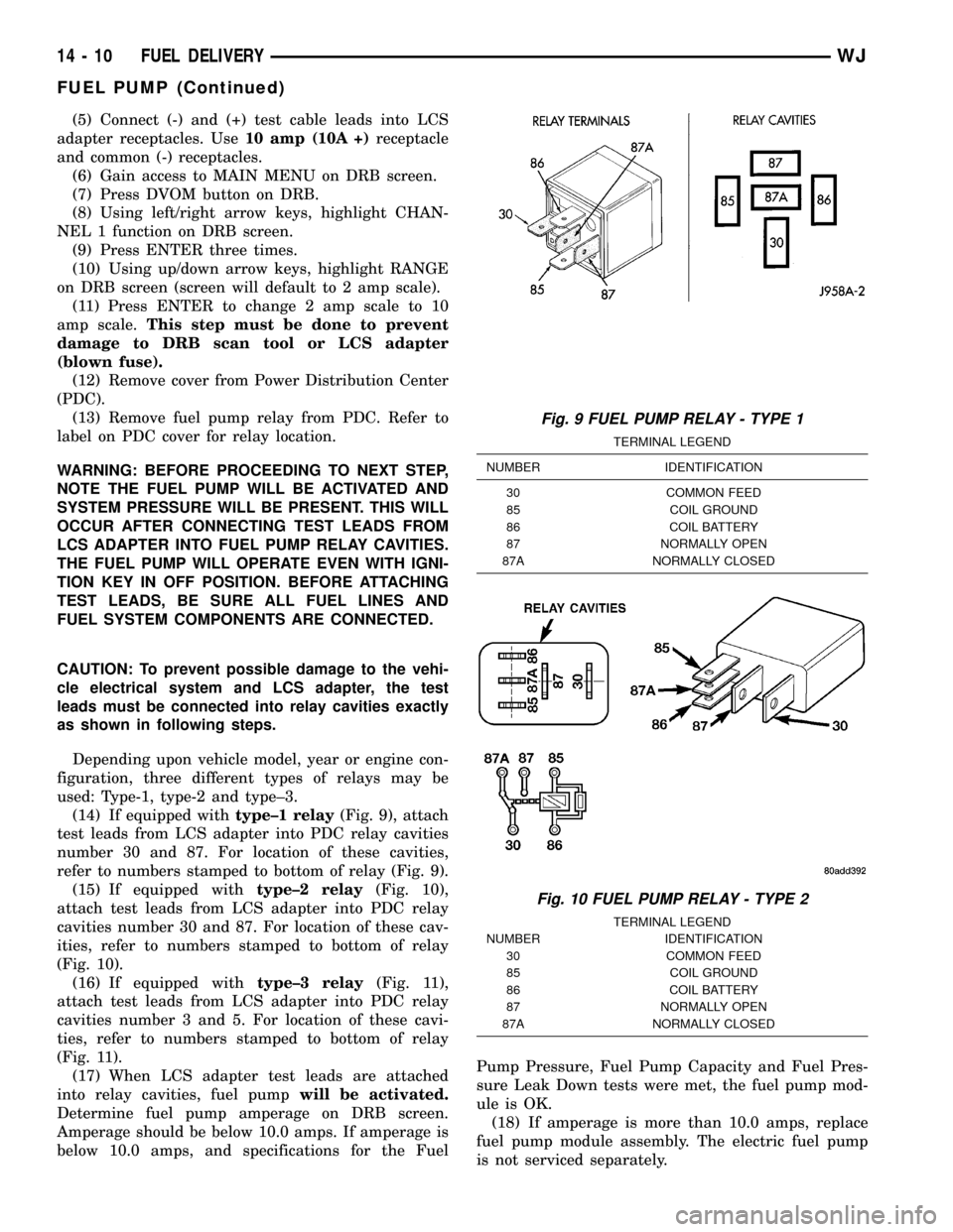
used: Type-1, type-2 and type±3.
(14) If equipped withtype±1 relay(Fig. 9), attach
test leads from LCS adapter into PDC relay cavities
number 30 and 87. For location of these cavities,
refer to numbers stamped to bottom of relay (Fig. 9).
(15) If equipped withtype±2 relay(Fig. 10),
attach test leads from LCS adapter into PDC relay
cavities number 30 and 87. For location of these cav-
ities, refer to numbers stamped to bottom of relay
(Fig. 10).
(16) If equipped withtype±3 relay(Fig. 11),
attach test leads from LCS adapter into PDC relay
cavities number 3 and 5. For location of these cavi-
ties, refer to numbers stamped to bottom of relay
(Fig. 11).
(17) When LCS adapter test leads are attached
into relay cavities, fuel pumpwill be activated.
Determine fuel pump amperage on DRB screen.
Amperage should be below 10.0 amps. If amperage is
below 10.0 amps, and specifications for the FuelPump Pressure, Fuel Pump Capacity and Fuel Pres-
sure Leak Down tests were met, the fuel pump mod-
ule is OK.
(18) If amperage is more than 10.0 amps, replace
fuel pump module assembly. The electric fuel pump
is not serviced separately.
Fig. 9 FUEL PUMP RELAY - TYPE 1
TERMINAL LEGEND
NUMBER IDENTIFICATION
30 COMMON FEED
85 COIL GROUND
86 COIL BATTERY
87 NORMALLY OPEN
87A NORMALLY CLOSED
Fig. 10 FUEL PUMP RELAY - TYPE 2
TERMINAL LEGEND
NUMBER IDENTIFICATION
30 COMMON FEED
85 COIL GROUND
86 COIL BATTERY
87 NORMALLY OPEN
87A NORMALLY CLOSED
14 - 10 FUEL DELIVERYWJ
FUEL PUMP (Continued)