2002 JEEP GRAND CHEROKEE service
[x] Cancel search: servicePage 1838 of 2199
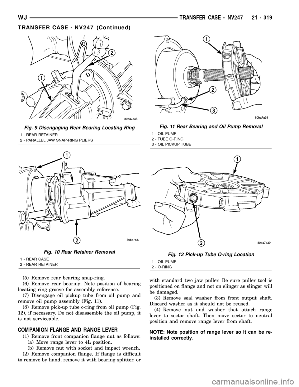
(5) Remove rear bearing snap-ring.
(6) Remove rear bearing. Note position of bearing
locating ring groove for assembly reference.
(7) Disengage oil pickup tube from oil pump and
remove oil pump assembly (Fig. 11).
(8) Remove pick-up tube o-ring from oil pump (Fig.
12), if necessary. Do not disassemble the oil pump, it
is not serviceable.
COMPANION FLANGE AND RANGE LEVER
(1) Remove front companion flange nut as follows:
(a) Move range lever to 4L position.
(b) Remove nut with socket and impact wrench.
(2) Remove companion flange. If flange is difficult
to remove by hand, remove it with bearing splitter, orwith standard two jaw puller. Be sure puller tool is
positioned on flange and not on slinger as slinger will
be damaged.
(3) Remove seal washer from front output shaft.
Discard washer as it should not be reused.
(4) Remove nut and washer that attach range
lever to sector shaft. Then move sector to neutral
position and remove range lever from shaft.
NOTE: Note position of range lever so it can be re-
installed correctly.
Fig. 9 Disengaging Rear Bearing Locating Ring
1 - REAR RETAINER
2 - PARALLEL JAW SNAP-RING PLIERS
Fig. 10 Rear Retainer Removal
1 - REAR CASE
2 - REAR RETAINER
Fig. 11 Rear Bearing and Oil Pump Removal
1 - OIL PUMP
2 - TUBE O-RING
3 - OIL PICKUP TUBE
Fig. 12 Pick-up Tube O-ring Location
1 - OIL PUMP
2 - O-RING
WJTRANSFER CASE - NV247 21 - 319
TRANSFER CASE - NV247 (Continued)
Page 1844 of 2199

INPUT AND LOW RANGE GEARS
Inspect the low range gear pinions and pinion pins.
Replace the low range gear if any of the pins or pin-
ions are worn or damaged.
Inspect the thrust washers, retainer, and snap-
ring. Replace the snap-ring if bent, or distorted.
Replace the thrust washers and retainer if worn,
cracked or damaged in any way.
Examine the input gear carefully. Be sure the gear
teeth and bearing surfaces are in good condition.
Replace the gear if wear or damage is evident.
Check the input gear pilot bearing. Rotate the
bearing and check for roughness or noise. Also check
bearing position in the bore. The bearing should be
recessed approximately 2.5 mm (0.100 in.) below the
top edge of the bore. The bearing should not be
seated at the bottom of the bore. Replace the bearing
if worn, or roughness is evident. Replace both the
gear and bearing if the bearing is a loose fit in the
bore.
GEAR CASE AND RETAINERS
Examine both case halves and retainers carefully.
Replace any retainer or case half if wear, cracks, or
other damage is evident.
Check condition of the low range annulus gear and
the shift rail bushing in the front case (Fig. 32). The
low range annulus gear is not a serviceable part.
Replace the gear and case as an assembly if the gear
is loose, worn, or damaged. The shift rail bushing is
a serviceable part and can be replaced if necessary.
Check the bushing in the rear retainer. Replace the
bushing if worn or scored.
Examine the sealing surfaces of both case halves
and retainers. Small burrs, or scratches on these sur-
faces can be reduced with crocus cloth or a fine tooth
file.
Examine condition of the shift rail bushing in the
front case. If the bushing is worn or damaged, it can
be removed with a blind hole type puller. A replace-
ment bushing can be installed with a suitable size
driver. Recess the bushing slightly below the edge of
the bore but do not seat it all the into the case.
GEARTRAIN
Inspect the mainshaft splines, gear teeth and bear-
ing surfaces carefully for evidence of wear, or dam-
age. Replace the shaft if necessary. do not attempt to
salvage it if damaged.
The shift rail and range fork are an assembly.
Replace both parts if either is damaged. However, the
nylon pads in the fork can be replaced if worn, or
cracked.
Inspect the transfer case snap-rings closely. Do not
attempt to salvage a distorted snap-ring by straight-ening or reshaping it. Replace any snap-ring that is
distorted, or worn.
Inspect the low range gear, input gear and the gear
thrust washers retainer, and snap-ring. The low
range gear is serviced as an assembly only. Replace
the gear if the case or pinions are damaged.
During inspection, also make sure the seal surface
of the input gear is in good condition. Minor nicks on
this surface can be reduced with crocus cloth. How-
ever, replace the gear if the seal surface is severely
scored or worn.
OIL PUMP AND PROGRESSIVE COUPLING
The oil pump and progressive coupling are not ser-
viceable components. Replace the coupling as an
assembly if it is damaged. Replace the oil pump as
an assembly if the gear teeth are worn, or if the
pump has become damaged.
BEARINGS AND SEALS
The transfer case seals should be replaced during
overhaul. Use new seals in the input gear bearing
retainer, front case and rear retainer. Also replace
the yoke seal washer and the detent plug O-ring.
Check condition of each transfer case bearing.
Replace any bearing exhibiting signs of roughness,
wear, or damage.
Fig. 32 Low Range Annulus Gear Location
1 - LOW RANGE ANNULUS GEAR
2 - SHIFT RAIL BUSHING
WJTRANSFER CASE - NV247 21 - 325
TRANSFER CASE - NV247 (Continued)
Page 1861 of 2199
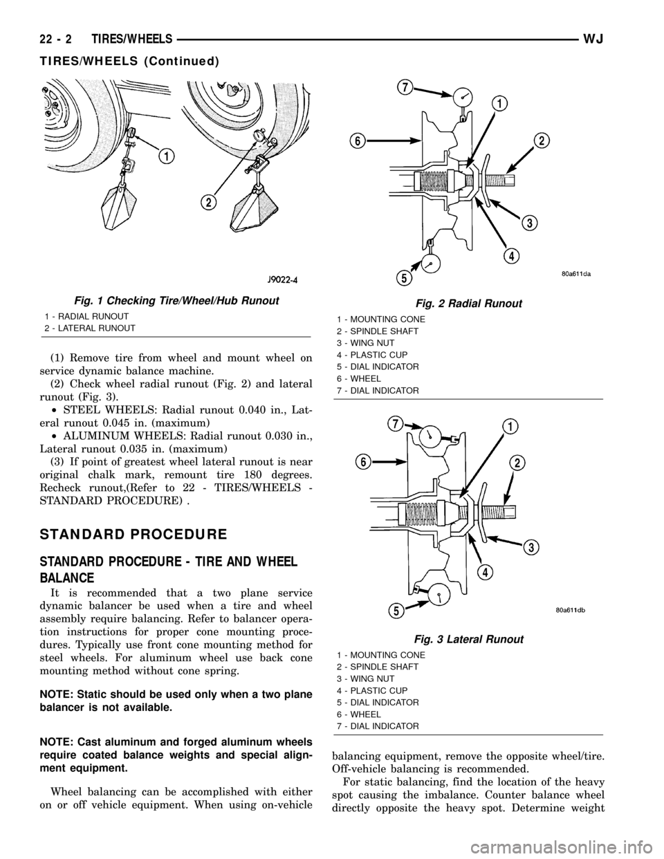
(1) Remove tire from wheel and mount wheel on
service dynamic balance machine.
(2) Check wheel radial runout (Fig. 2) and lateral
runout (Fig. 3).
²STEEL WHEELS: Radial runout 0.040 in., Lat-
eral runout 0.045 in. (maximum)
²ALUMINUM WHEELS: Radial runout 0.030 in.,
Lateral runout 0.035 in. (maximum)
(3) If point of greatest wheel lateral runout is near
original chalk mark, remount tire 180 degrees.
Recheck runout,(Refer to 22 - TIRES/WHEELS -
STANDARD PROCEDURE) .
STANDARD PROCEDURE
STANDARD PROCEDURE - TIRE AND WHEEL
BALANCE
It is recommended that a two plane service
dynamic balancer be used when a tire and wheel
assembly require balancing. Refer to balancer opera-
tion instructions for proper cone mounting proce-
dures. Typically use front cone mounting method for
steel wheels. For aluminum wheel use back cone
mounting method without cone spring.
NOTE: Static should be used only when a two plane
balancer is not available.
NOTE: Cast aluminum and forged aluminum wheels
require coated balance weights and special align-
ment equipment.
Wheel balancing can be accomplished with either
on or off vehicle equipment. When using on-vehiclebalancing equipment, remove the opposite wheel/tire.
Off-vehicle balancing is recommended.
For static balancing, find the location of the heavy
spot causing the imbalance. Counter balance wheel
directly opposite the heavy spot. Determine weight
Fig. 1 Checking Tire/Wheel/Hub Runout
1 - RADIAL RUNOUT
2 - LATERAL RUNOUT
Fig. 2 Radial Runout
1 - MOUNTING CONE
2 - SPINDLE SHAFT
3 - WING NUT
4 - PLASTIC CUP
5 - DIAL INDICATOR
6 - WHEEL
7 - DIAL INDICATOR
Fig. 3 Lateral Runout
1 - MOUNTING CONE
2 - SPINDLE SHAFT
3 - WING NUT
4 - PLASTIC CUP
5 - DIAL INDICATOR
6 - WHEEL
7 - DIAL INDICATOR
22 - 2 TIRES/WHEELSWJ
TIRES/WHEELS (Continued)
Page 1869 of 2199

SPARE TIRE
DESCRIPTION - SPARE / TEMPORARY TIRE
The temporary spare tire is designed for emer-
gency use only. The original tire should be repaired
or replaced at the first opportunity, then reinstalled.
Do not exceed speeds of 50 M.P.H. when using the
temporary spare tire. Refer to Owner's Manual for
complete details.
WHEELS
DESCRIPTION
The rim size is on the vehicle safety certification
label located on the drivers door shut face. The size
of the rim is determined by the drivetrain package.
Original equipment wheels/rims are designed for
operation up to the specified maximum vehicle capac-
ity.
All models use stamped steel, cast aluminum or
forged aluminum wheels. Every wheel has raised sec-
tions between the rim flanges and rim drop well
called safety humps (Fig. 18) .
Initial inflation of the tire forces the bead over
these raised sections. In case of rapid loss of air pres-
sure, the raised sections help hold the tire on the
wheel.
The wheel studs and nuts are designed for specific
applications. All aluminum and some steel wheels
have wheel stud nuts with an enlarged nose. This
enlarged nose is necessary to ensure proper retentionof the wheels. Do not use replacement studs or nuts
with a different design or lesser quality.
DIAGNOSIS AND TESTING - WHEEL
INSPECTION
Inspect wheels for:
²Excessive run out
²Dents or cracks
²Damaged wheel lug nut holes
²Air Leaks from any area or surface of the rim
NOTE: Do not attempt to repair a wheel by hammer-
ing, heating or welding.
If a wheel is damaged an original equipment
replacement wheel should be used. When obtaining
replacement wheels, they should be equivalent in
load carrying capacity. The diameter, width, offset,
pilot hole and bolt circle of the wheel should be the
same as the original wheel.
WARNING: FAILURE TO USE EQUIVALENT
REPLACEMENT WHEELS MAY ADVERSELY
AFFECT THE SAFETY AND HANDLING OF THE
VEHICLE. USED WHEELS ARE NOT RECOM-
MENDED. THE SERVICE HISTORY OF THE WHEEL
MAY HAVE INCLUDED SEVERE TREATMENT OR
VERY HIGH MILEAGE. THE RIM COULD FAIL WITH-
OUT WARNING.
STANDARD PROCEDURE - WHEEL
REPLACEMENT
The wheel studs and nuts are designed for specific
applications. They must be replaced with equivalent
parts. Do not use replacement parts of lesser quality
or a substitute design. All aluminum and some steel
wheels have wheel stud nuts which feature an
enlarged nose. This enlarged nose is necessary to
ensure proper retention of the aluminum wheels.
NOTE: Do not use chrome plated lug nuts with
chrome plated wheels.
Before installing the wheel, be sure to remove any
build up of corrosion on the wheel mounting surfaces.
Ensure wheels are installed with good metal-to-metal
contact. Improper installation could cause loosening
of wheel nuts. This could affect the safety and han-
dling of your vehicle.
To install the wheel, first position it properly on
the mounting surface. All wheel nuts should then be
tightened just snug. Gradually tighten them in
sequence to the proper torque specification.Never
use oil or grease on studs or nuts.
Wheels must be replaced if they have:
²Excessive runout
Fig. 18 Safety Rim
1 - FLANGE
2 - RIDGE
3 - WELL
22 - 10 TIRES/WHEELSWJ
Page 1870 of 2199
²Bent or dented
²Leak air through welds
²Have damaged bolt holes
Wheel repairs employing hammering, heating, or
welding are not allowed.
Original equipment wheels are available through
your dealer. Replacement wheels from any other
source should be equivalent in:
²Load carrying capacity
²Diameter
²Width²Offset
²Mounting configuration
Failure to use equivalent replacement wheels may
affect the safety and handling of your vehicle.
Replacement withusedwheels is not recommended.
Their service history may have included severe treat-
ment.
SPECIFICATIONS
TORQUE CHART
TORQUE SPECIFICATIONS
DESCRIPTION N´m Ft. Lbs. In. Lbs.
Lug Nut
1/2 X 20 with 60É Cone115-150 85-115 Ð
STUDS
REMOVAL
CAUTION: Do not use a hammer to remove wheel
studs.
(1) Raise and support vehicle.
(2) Remove wheel and tire assembly.
(3) Remove brake caliper, caliper adapter and
rotor,(Refer to 5 - BRAKES/HYDRAULIC/MECHAN-
ICAL/ROTORS - REMOVAL).
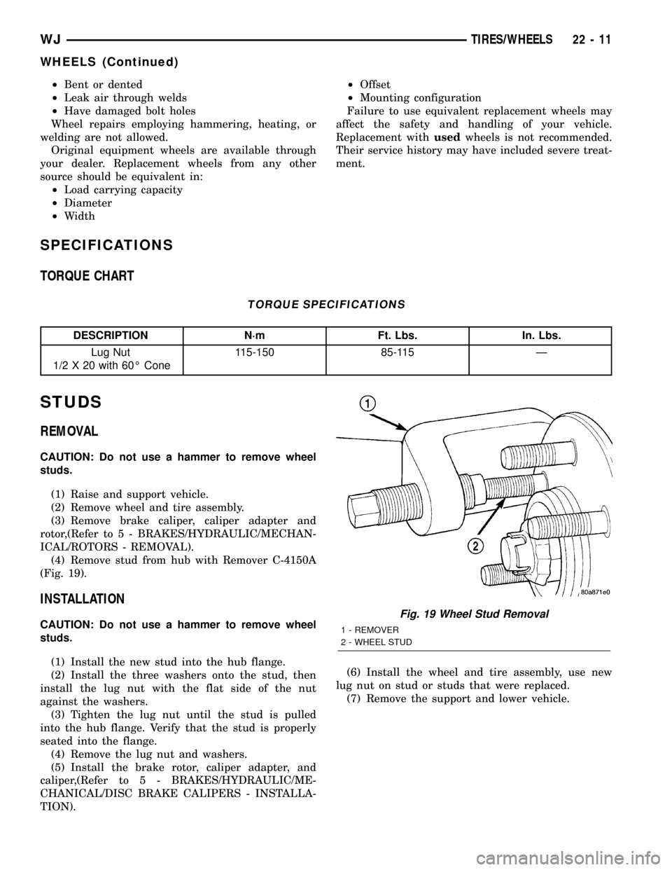
(4) Remove stud from hub with Remover C-4150A
(Fig. 19).
INSTALLATION
CAUTION: Do not use a hammer to remove wheel
studs.
(1) Install the new stud into the hub flange.
(2) Install the three washers onto the stud, then
install the lug nut with the flat side of the nut
against the washers.
(3) Tighten the lug nut until the stud is pulled
into the hub flange. Verify that the stud is properly
seated into the flange.
(4) Remove the lug nut and washers.
(5) Install the brake rotor, caliper adapter, and
caliper,(Refer to 5 - BRAKES/HYDRAULIC/ME-
CHANICAL/DISC BRAKE CALIPERS - INSTALLA-
TION).(6) Install the wheel and tire assembly, use new
lug nut on stud or studs that were replaced.
(7) Remove the support and lower vehicle.Fig. 19 Wheel Stud Removal
1 - REMOVER
2 - WHEEL STUD
WJTIRES/WHEELS 22 - 11
WHEELS (Continued)
Page 1871 of 2199
TIRE PRESSURE MONITORING
DESCRIPTION
The EVIC will monitor the tire pressure signals
from the five tire sensors and determine if any tire
has gone below the low pressure threshold or raised
above the high pressure threshold. Refer to the table
below.
LOW TIRE PRESSURE THRESHOLDS
SYSTEM STATUS
INDICATORTIRE PRESSURE
ON 179 kPa (26 PSI)
OFF 214 kPa (31 PSI)
HIGH TIRE PRESSURE THRESHOLDS
SYSTEM STATUS
INDICATORTIRE PRESSURE
ON 310 kPa (45 PSI)
OFF 276 kPa (40 PSI)
The Remote Tire Pressure Monitors (RTPM) are
not internally serviceable. For a Sensor Failure or
Low Battery fault, the RTPM must be replaced.
OPERATION
If equipped with the Tire Pressure Monitoring Sys-
tem, each of the vehicle's five wheels will have a
valve stem with a pressure sensor and radio trans-
mitter built in. Signals from the tire pressure sensors
are received and interpreted by the Electronic Vehi-
cle Information Center (EVIC). A sensor in a
mounted wheel will broadcast its detected pressure
once per minute when the vehicle is moving faster
than 40 km/h (25 mph). The spare tire sensor will
broadcast once every hour. Each sensor's broadcast is
uniquely coded so that the EVIC can determine loca-
tion. The individual tire pressures can be displayed
graphically on the EVIC
DIAGNOSIS AND TESTING - TIRE PRESSURE
MONITORING SYSTEM
All Tire Pressure Monitoring System Faults are
specific to one location. If a9BATTERY LOW9or
9SENSOR FAILURE9fault is detected, the location
will be displayed. The appropriate sensor/transmitter
can then be replaced. If a single sensor/transmitter
cannot be detected by the EVIC, replace that sensor
transmitter. If none of the sensors/transmitters can
be detected, refer to symptoms in the EVIC section.
For additional system description and diagnosis,
refer to Tire Pressure Monitoring in the Body Diag-
nostic manual.
SENSOR
REMOVAL - TIRE PRESSURE SENSOR/
TRANSMITTER
(1) Remove the tire/wheel from the vehicle.
CAUTION: When removing the stick on balancing
weights from the wheel, do not use an abrasive
cleaner or a cleaner which will damage the protec-
tive finish on the wheel.
(2) Remove the balancing weights from the wheel.
NOTE: The cap used on this valve stem contains an
O-ring seal to prevent contamination and moisture
from entering the valve stem. Retain this valve stem
cap for re-use. Do not substitute a regular valve
stem cap in its place.
(3) Remove the cap from the valve stem.
NOTE: The valve stem used on this vehicle is made
of aluminum and the core is nickel plated brass.
The original valve stem core must be reinstalled
and not substituted for a valve stem core made of a
different material. This is required to prevent corro-
sion in the valve stem caused by the different met-
als.
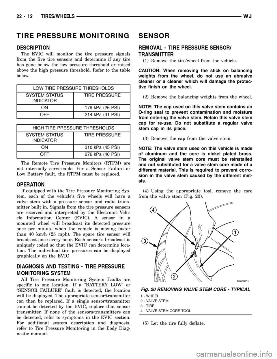
(4) Using the appropriate tool, remove the core
from the valve stem (Fig. 20).
(5) Let the tire fully deflate.
Fig. 20 REMOVING VALVE STEM CORE - TYPICAL
1 - WHEEL
2 - VALVE STEM
3 - TIRE
4 - VALVE STEM CORE TOOL
22 - 12 TIRES/WHEELSWJ
Page 1876 of 2199
(2) Apply silicone lubricant to a cloth and wipe it
on door seals to avoid over-spray that can soil pas-
senger's clothing.
(3) Before applying lubricant, the component
should be wiped clean. After lubrication, any excess
lubricant should be removed.
(4) The hood latch, latch release mechanism, latch
striker, and safety latch should be lubricated period-
ically.
(5) The door lock cylinders should be lubricated
twice each year (preferably autumn and spring).
(a) Spray a small amount of lock cylinder lubri-
cant directly into the lock cylinder.
(b) Apply a small amount to the key and insert
it into the lock cylinder.
(c) Rotate it to the locked position and then back
to the unlocked position several times.(d) Remove the key. Wipe the lubricant from it
with a clean cloth to avoid soiling of clothing.
STANDARD PROCEDURE - DRILLING AND
WELDING
When holes must be drilled or punched in an inner
body panel, verify depth of space to the outer body
panel, electrical wiring, or other components. Dam-
age to vehicle can result.
Do not weld exterior panels unless combustible
material on the interior of vehicle is removed from
the repair area. Fire or hazardous conditions, can
result.
Always have a fire extinguisher ready for use when
welding.
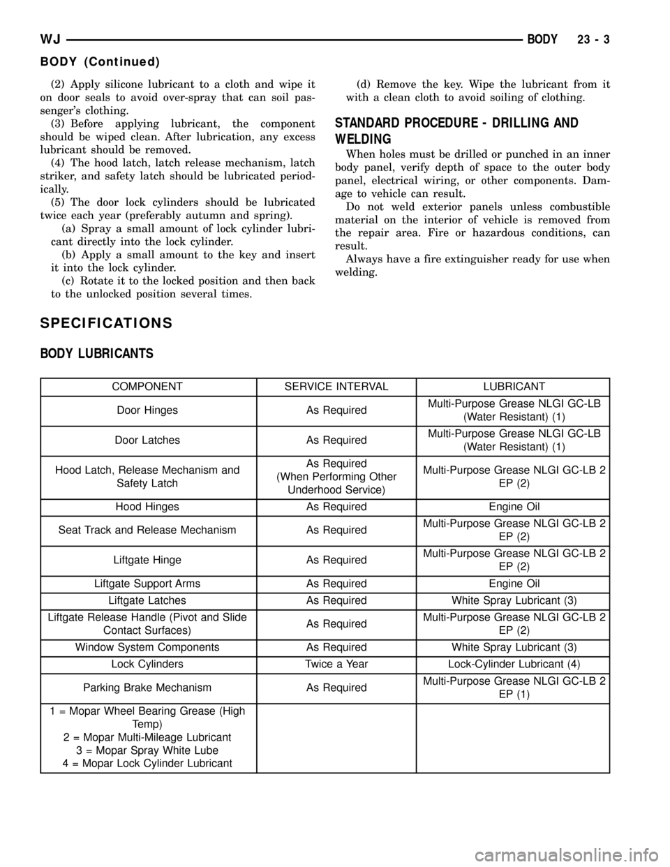
SPECIFICATIONS
BODY LUBRICANTS
COMPONENT SERVICE INTERVAL LUBRICANT
Door Hinges As RequiredMulti-Purpose Grease NLGI GC-LB
(Water Resistant) (1)
Door Latches As RequiredMulti-Purpose Grease NLGI GC-LB
(Water Resistant) (1)
Hood Latch, Release Mechanism and
Safety LatchAs Required
(When Performing Other
Underhood Service)Multi-Purpose Grease NLGI GC-LB 2
EP (2)
Hood Hinges As Required Engine Oil
Seat Track and Release Mechanism As RequiredMulti-Purpose Grease NLGI GC-LB 2
EP (2)
Liftgate Hinge As RequiredMulti-Purpose Grease NLGI GC-LB 2
EP (2)
Liftgate Support Arms As Required Engine Oil
Liftgate Latches As Required White Spray Lubricant (3)
Liftgate Release Handle (Pivot and Slide
Contact Surfaces)As RequiredMulti-Purpose Grease NLGI GC-LB 2
EP (2)
Window System Components As Required White Spray Lubricant (3)
Lock Cylinders Twice a Year Lock-Cylinder Lubricant (4)
Parking Brake Mechanism As RequiredMulti-Purpose Grease NLGI GC-LB 2
EP (1)
1 = Mopar Wheel Bearing Grease (High
Temp)
2 = Mopar Multi-Mileage Lubricant
3 = Mopar Spray White Lube
4 = Mopar Lock Cylinder Lubricant
WJBODY 23 - 3
BODY (Continued)
Page 1904 of 2199
(4) Remove the screws attaching the supports to
the roof panel.
(5) Separate the supports from the roof panel.
NOTE: If a crossbar needs to be serviced, the for-
ward or rearward supports will have to be removed.
INSTALLATION
(1) Position the supports on the roof panel and
install the screw. Be sure that the gasket is properly
seated.
(2) Position the luggage rack on the supports.
(3) Install the screws attaching the side rails to
the supports.
(4) Position the supports covers on the supports
and press into place.
SIDE VIEW MIRROR GLASS
REMOVAL
(1) With damaged mirror still on vehicle, position
mirror glass down and centered.
(2) Position a wide leverage device between the
bottom edge of the glass and the mirror shell.
(3) Firmly apply pressure in an upward direction
until glass assembly disengages from adapter plate.
(4) Disconnect the heater wire terminal, if
equipped, or the EC plug, if equipped.
INSTALLATION
(1) Connect the heater wire terminal or the EC
plug, if equipped.
(2) Position the replacement glass in the mirror
shell and align the four snap tabs with the four cav-
ities in the shell.
(3) Apply firm pressure inward until the replace-
ment glass assembly engages with the adapter plate.
Correct assembly will result in a firm click. Glass
assembly should exhibit even gaps to the shell when
complete.
(4) Pull lightly on corners of glass assembly to
ensure all four snaps are engaged and there is no
free play.
SIDE VIEW MIRROR
REMOVAL
(1) Remove door trim panel, refer to (Refer to 23 -
BODY/DOOR - FRONT/TRIM PANEL - REMOVAL).
(2) Disengage power mirror harness connector, if
equipped.
(3) Remove mirror flag seal.
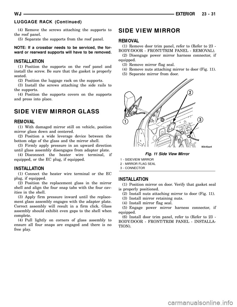
(4) Remove nuts attaching mirror to door (Fig. 11).
(5) Separate mirror from door.
INSTALLATION
(1) Position mirror on door. Verify that gasket seal
is properly positioned.
(2) Install nuts attaching mirror to door (Fig. 11).
(3) Install mirror retaining nuts.
(4) Install mirror flag seal.
(5) Engage power mirror harness connector, if
equipped.
(6) Install door trim panel, refer to (Refer to 23 -
BODY/DOOR - FRONT/TRIM PANEL - INSTALLA-
TION).
Fig. 11 Side View Mirror
1 - SIDEVIEW MIRROR
2 - MIRROR FLAG SEAL
3 - CONNECTOR
WJEXTERIOR 23 - 31
LUGGAGE RACK (Continued)