2002 JEEP GRAND CHEROKEE lift gate trim
[x] Cancel search: lift gate trimPage 1882 of 2199

LIFTGATE
REMOVAL
CAUTION: DO NOT DISCONNECT THE SUPPORT ROD
CYLINDERS WITH THE LIFTGATE CLOSED. THE SUP-
PORT ROD PISTONS ARE OPERATED BY HIGH PRES-
SURE GAS. THIS PRESSURE COULD CAUSE DAMAGE
AND /OR PERSONAL INJURY IF THEY ARE REMOVED
WHILE THE PISTONS ARE COMPRESSED.
(1) Open the liftgate. Support the liftgate for ease
of repair.
(2) Remove the liftgate trim panel.
(3) Remove the prop rods from the liftgate.
(4) Unplug the wire harnesses and disconnect the
washer hose.
(5) Mark the hinge location with a wax pencil or
other suitable device (Fig. 5).
(6) Remove the hinge screws and remove liftgate
from vehicle.
INSTALLATION
(1) Position the liftgate on the vehicle and align
the witness marks.
(2) Install the hinge screws at liftgate. Tighten
hinge screws to 28N´m (21ft. lbs.).
(3) Connect the wire harnesses and the washer
hose.
(4) Install the trim panel.
(5) Install the prop rods.
(6) Close the liftgate and check for proper latching
and alignment.
ADJUSTMENTS
LIFTGATE ADJUSTMENT
The position of the liftgate can be adjusted upward
or downward by the use of slots in the hinge. An
inward or outward adjustment is achieved by use of
slots in the body. If an inward or outward adjustment
is needed, use 3MŸ Fast and Firm or equivalent on
the hinge to body mating surface as a sealant.
TRIM PANEL
REMOVAL
REMOVAL - LIFTGATE TRIM PANEL
NOTE: The liftgate trim panel is attached with
screws and spring clips.
(1) Raise the liftgate.
(2) Remove the screws securing the liftgate trim
panel to the liftgate (Fig. 6).
(3) Disconnect the rear window defroster wires.
(4) Using a trim stick, or other suitable tool, pry
the liftgate trim panel off the liftgate.
Fig. 5 Liftgate
1 - HINGE
2 - LIFTGATE
Fig. 6 Liftgate Trim Panel
1 - LIFTGATE
2 - LIFTGATE TRIM PANEL
WJDECKLID/HATCH/LIFTGATE/TAILGATE 23 - 9
Page 1883 of 2199

REMOVAL - LOWER LIFTGATE OPENING TRIM
PANEL
(1) Remove screws at outboard end of lower lift-
gate trim panel.
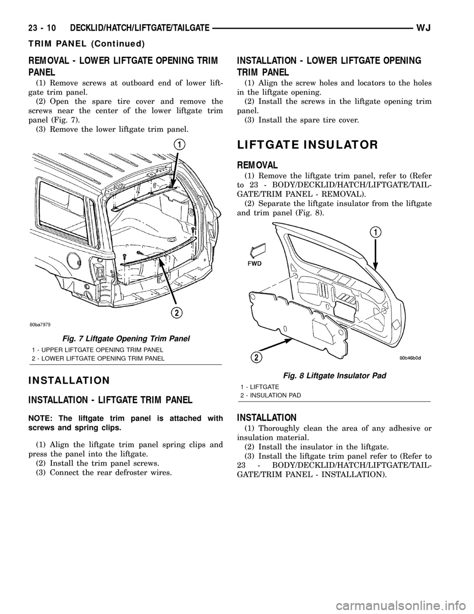
(2) Open the spare tire cover and remove the
screws near the center of the lower liftgate trim
panel (Fig. 7).
(3) Remove the lower liftgate trim panel.
INSTALLATION
INSTALLATION - LIFTGATE TRIM PANEL
NOTE: The liftgate trim panel is attached with
screws and spring clips.
(1) Align the liftgate trim panel spring clips and
press the panel into the liftgate.
(2) Install the trim panel screws.
(3) Connect the rear defroster wires.
INSTALLATION - LOWER LIFTGATE OPENING
TRIM PANEL
(1) Align the screw holes and locators to the holes
in the liftgate opening.
(2) Install the screws in the liftgate opening trim
panel.
(3) Install the spare tire cover.
LIFTGATE INSULATOR
REMOVAL
(1) Remove the liftgate trim panel, refer to (Refer
to 23 - BODY/DECKLID/HATCH/LIFTGATE/TAIL-
GATE/TRIM PANEL - REMOVAL).
(2) Separate the liftgate insulator from the liftgate
and trim panel (Fig. 8).
INSTALLATION
(1) Thoroughly clean the area of any adhesive or
insulation material.
(2) Install the insulator in the liftgate.
(3) Install the liftgate trim panel refer to (Refer to
23 - BODY/DECKLID/HATCH/LIFTGATE/TAIL-
GATE/TRIM PANEL - INSTALLATION).
Fig. 7 Liftgate Opening Trim Panel
1 - UPPER LIFTGATE OPENING TRIM PANEL
2 - LOWER LIFTGATE OPENING TRIM PANEL
Fig. 8 Liftgate Insulator Pad
1 - LIFTGATE
2 - INSULATION PAD
23 - 10 DECKLID/HATCH/LIFTGATE/TAILGATEWJ
TRIM PANEL (Continued)
Page 1942 of 2199

INTERIOR
TABLE OF CONTENTS
page page
A-PILLAR TRIM
REMOVAL.............................69
INSTALLATION.........................69
ASSIST HANDLE
REMOVAL.............................70
INSTALLATION.........................70
B-PILLAR LOWER TRIM
REMOVAL.............................70
INSTALLATION.........................70
B-PILLAR UPPER TRIM
REMOVAL.............................71
INSTALLATION.........................71
CARPETS AND FLOOR MATS
REMOVAL
REMOVAL - FRONT CARPET............71
REMOVAL - CARGO AREA CARPET.......71
INSTALLATION
INSTALLATION - FRONT CARPET.........71
INSTALLATION - CARGO AREA CARPET . . . 72
COWL TRIM
REMOVAL.............................72
INSTALLATION.........................72
C-PILLAR TRIM
REMOVAL.............................72
INSTALLATION.........................72
DOOR SILL SCUFF PLATE
REMOVAL.............................74
INSTALLATION.........................74
DOOR SILL TRIM
REMOVAL.............................74INSTALLATION.........................74
D-PILLAR TRIM
REMOVAL.............................75
INSTALLATION.........................75
FLOOR CONSOLE
REMOVAL.............................76
INSTALLATION.........................76
HEADLINER
REMOVAL.............................77
INSTALLATION.........................77
LIFTGATE OPENING UPPER TRIM
REMOVAL.............................79
INSTALLATION.........................79
QUARTER TRIM PANEL
REMOVAL.............................79
INSTALLATION.........................79
REAR STORAGE BOX
REMOVAL.............................79
INSTALLATION.........................80
REAR VIEW MIRROR
REMOVAL.............................80
INSTALLATION
INSTALLATION.......................80
INSTALLATION - REARVIEW MIRROR
SUPPORT BRACKET...................80
SUN VISOR
REMOVAL.............................80
INSTALLATION.........................80
A-PILLAR TRIM
REMOVAL
The A-pillar trim is attached to the A-pillar with
spring clips.
(1) Grasp A-pillar trim and pull trim outward from
A-pillar (Fig. 1).
(2) Separate A-pillar trim from A-pillar.
INSTALLATION
(1) Position A-pillar trim on A-pillar and, starting
at the bottom, press into place (Fig. 1).
(2) Using a trim stick or other suitable tool, care-
fully cover the edge of the trim with weatherstrip.
Fig. 1 A-Pillar Trim
1 - A-PILLAR TRIM
2 - A-PILLAR
3 - SPRING CLIP
WJINTERIOR 23 - 69
Page 1944 of 2199

(4) Install screw attaching B-pillar lower trim to
B-pillar.
(5) Install screw attaching front of B-pillar lower
trim to floor.
(6) Install screw attaching front of quarter panel
trim to floor.
(7) Install front seat shoulder belt anchor bolt.
(8) Install front seat shoulder belt height adjust-
ment knob and turning loop.
(9) Install front door sill trim (Refer to 23 - BODY/
INTERIOR/DOOR SILL TRIM - INSTALLATION).
B-PILLAR UPPER TRIM
REMOVAL
(1) Remove shoulder belt height adjustment knob.
(2) Remove front seat belt turning loop.
(3) Remove the screw attaching lower B pillar
trim.
(4) Pull lower B pillar trim out far enough to
remove upper trim panel.
(5) Grasp upper B-pillar trim and pull outward to
detach from B-pillar (Fig. 2).
INSTALLATION
(1) Position trim panel on B-pillar (Fig. 2).
(2) Ensure trim panel covers inner edge of door
opening weatherstrip and press inward to seat.
(3) Install screw attaching lower B pillar trim
panel.
(4) Install front seat belt turning loop.
(5) Install shoulder belt height adjustment knob.
CARPETS AND FLOOR MATS
REMOVAL
REMOVAL - FRONT CARPET
(1) Remove door sill trim (Refer to 23 - BODY/IN-
TERIOR/DOOR SILL TRIM - REMOVAL).
(2) Remove the B-pillar lower trim, refer to (Refer
to 23 - BODY/INTERIOR/B-PILLAR LOWER TRIM -
REMOVAL).
(3) Remove front seats (Refer to 23 - BODY/
SEATS/SEAT - REMOVAL).
(4) Remove the rear seats lower cushions (Refer to
23 - BODY/SEATS/SEAT CUSHION - REMOVAL).
(5) Remove center floor console (Refer to 23 -
BODY/INTERIOR/FLOOR CONSOLE - REMOVAL).
(6) Remove any other interfering trim or molding.
(7) Lift carpet and mat from floor panel.
REMOVAL - CARGO AREA CARPET
(1) Lift tailgate.
(2) Fold rear seat cushions forward.
(3) Remove rear seat backs (Refer to 23 - BODY/
SEATS/REAR SEAT BACK - REMOVAL).
(4) Remove the rear shoulder belts (Refer to 8 -
ELECTRICAL/RESTRAINTS/REAR SEAT BELT &
RETRACTOR - REMOVAL).
(5) Remove the retractable security cargo cover
assembly.
(6) Remove the spare tire cover.
(7) Remove the rear cargo tie down footman loops.
The side mounted footman loops are retained by
screws. The floor footman loops are riveted (Fig. 3).
(8) Remove the C pillar trim (Refer to 23 - BODY/
INTERIOR/C-PILLAR TRIM - REMOVAL).
(9) Remove the CD changer, if equipped (Refer to 8
- ELECTRICAL/AUDIO/CD CHANGER - REMOV-
AL).
(10) Remove the Infinity amp, if equipped (Refer to
8 - ELECTRICAL/AUDIO/AMPLIFIER - REMOVAL).
(11) Lift the carpet.
INSTALLATION
INSTALLATION - FRONT CARPET
(1) Carefully lay the carpet and mat on the floor
panel. Align the carpet to allow installation of the
components fastened to the floor panel.
(2) Install the center console (Refer to 23 - BODY/
INTERIOR/FLOOR CONSOLE - INSTALLATION).
(3) Install the front seats (Refer to 23 - BODY/
SEATS/SEAT - INSTALLATION).
(4) Install the rear seat cushions (Refer to 23 -
BODY/SEATS/SEAT CUSHION - INSTALLATION).
Fig. 3 Cargo Area Carpet
1 - CARGO AREA CARPET
2 - RIVET
3 - CARGO TIE-DOWN LOOP
WJINTERIOR 23 - 71
B-PILLAR LOWER TRIM (Continued)
Page 1948 of 2199

D-PILLAR TRIM
REMOVAL
The D-pillar trim is attached to the D-pillar with
spring clips (Fig. 7).
(1) Remove liftgate opening upper trim panel
(Refer to 23 - BODY/INTERIOR/LIFTGATE OPEN-
ING UPPER TRIM - REMOVAL).
(2) Grasp D-pillar trim and pull outward from
D-pillar.
(3) Separate D-pillar trim from D-pillar.
INSTALLATION
(1) Position D-pillar trim panel at D-pillar and
press into place.
(2) Install upper liftgate opening trim panel (Refer
to 23 - BODY/INTERIOR/LIFTGATE OPENING
UPPER TRIM - INSTALLATION).
Fig. 6 Sill Trim Molding
1 - B-PILLAR UPPER TRIM
2 - ACCESS COVER
3 - B-PILLAR LOWER TRIM
4 - PLASTIC NUT
5 - COWL LOWER TRIM6 - CLIP
7 - SCUFF PLATE
8 - SILL TRIM
9 - A-PILLAR TRIM
Fig. 7 D Pillar Upper Trim
1 - D PILLAR UPPER TRIM
WJINTERIOR 23 - 75
DOOR SILL TRIM (Continued)
Page 1950 of 2199

HEADLINER
REMOVAL
CAUTION: The headliner is a one-piece, molded
component. It has limited flexibility and must not be
bent. Damage may possibly result.
(1) Record radio presets and disconnect negative
battery cable.
(2) Remove A pillar trim moldings (Refer to 23 -
BODY/INTERIOR/A-PILLAR TRIM - REMOVAL).
(3) Remove B pillar upper trim moldings (Refer to
23 - BODY/INTERIOR/B-PILLAR UPPER TRIM -
REMOVAL).
(4) Remove C pillar trim moldings (Refer to 23 -
BODY/INTERIOR/C-PILLAR TRIM - REMOVAL).
(5) Remove D pillar trim molding (Refer to 23 -
BODY/INTERIOR/D-PILLAR TRIM - REMOVAL).
(6) Remove the sun visors (Refer to 23 - BODY/IN-
TERIOR/SUN VISOR - REMOVAL).
(7) Disconnect the vanity lamp electrical connector.
(8) Remove assist handles from roof rails (Refer to
23 - BODY/INTERIOR/ASSIST HANDLE - REMOV-
AL).
(9) Remove dome lamp and overhead console, if
equipped.
(10) Remove rear cargo/dome lamp.
(11) Remove sun roof pinch welt, if equipped.
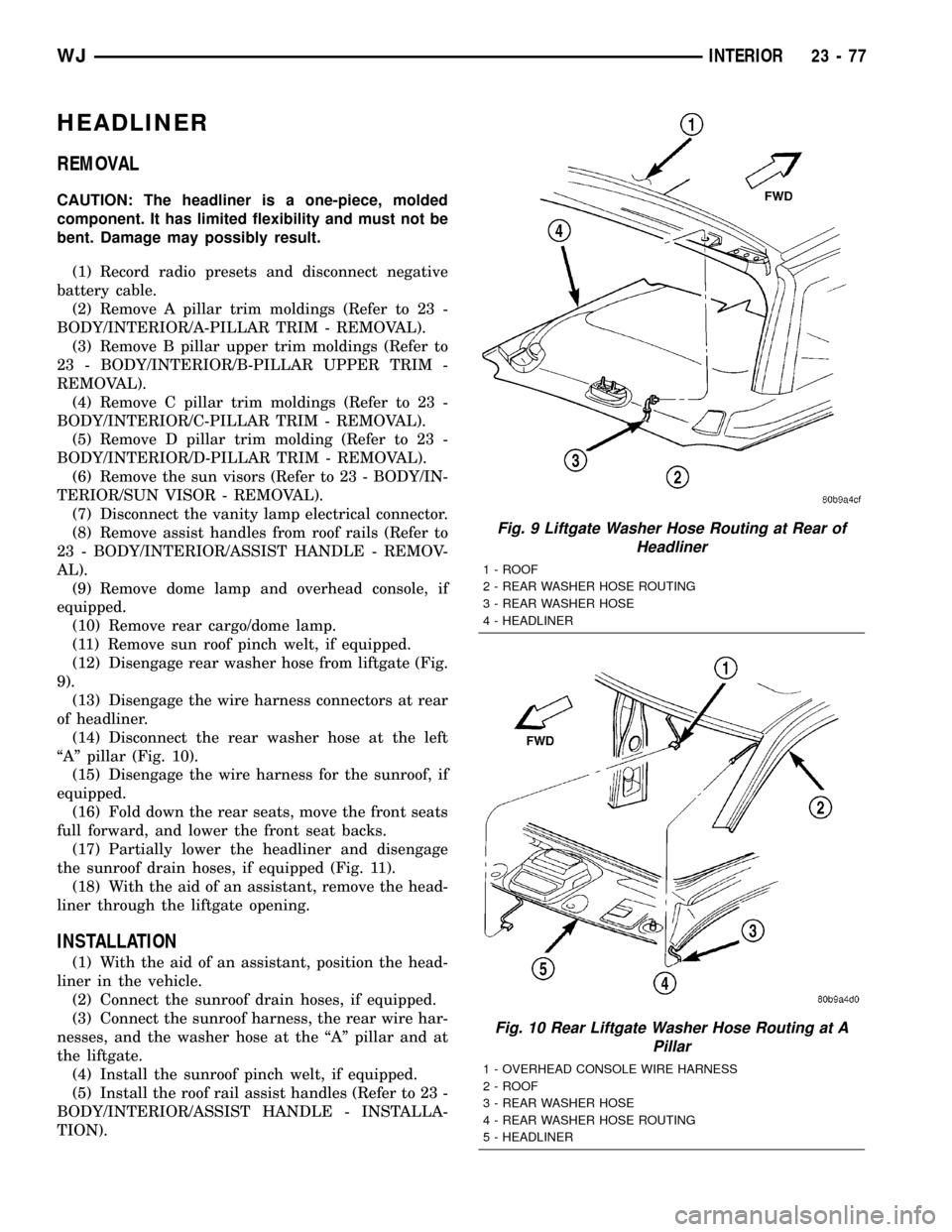
(12) Disengage rear washer hose from liftgate (Fig.
9).
(13) Disengage the wire harness connectors at rear
of headliner.
(14) Disconnect the rear washer hose at the left
ªAº pillar (Fig. 10).
(15) Disengage the wire harness for the sunroof, if
equipped.
(16) Fold down the rear seats, move the front seats
full forward, and lower the front seat backs.
(17) Partially lower the headliner and disengage
the sunroof drain hoses, if equipped (Fig. 11).
(18) With the aid of an assistant, remove the head-
liner through the liftgate opening.
INSTALLATION
(1) With the aid of an assistant, position the head-
liner in the vehicle.
(2) Connect the sunroof drain hoses, if equipped.
(3) Connect the sunroof harness, the rear wire har-
nesses, and the washer hose at the ªAº pillar and at
the liftgate.
(4) Install the sunroof pinch welt, if equipped.
(5) Install the roof rail assist handles (Refer to 23 -
BODY/INTERIOR/ASSIST HANDLE - INSTALLA-
TION).
Fig. 9 Liftgate Washer Hose Routing at Rear of
Headliner
1 - ROOF
2 - REAR WASHER HOSE ROUTING
3 - REAR WASHER HOSE
4 - HEADLINER
Fig. 10 Rear Liftgate Washer Hose Routing at A
Pillar
1 - OVERHEAD CONSOLE WIRE HARNESS
2 - ROOF
3 - REAR WASHER HOSE
4 - REAR WASHER HOSE ROUTING
5 - HEADLINER
WJINTERIOR 23 - 77
Page 1952 of 2199

LIFTGATE OPENING UPPER
TRIM
REMOVAL
The upper liftgate opening trim is held on with
spring clips.
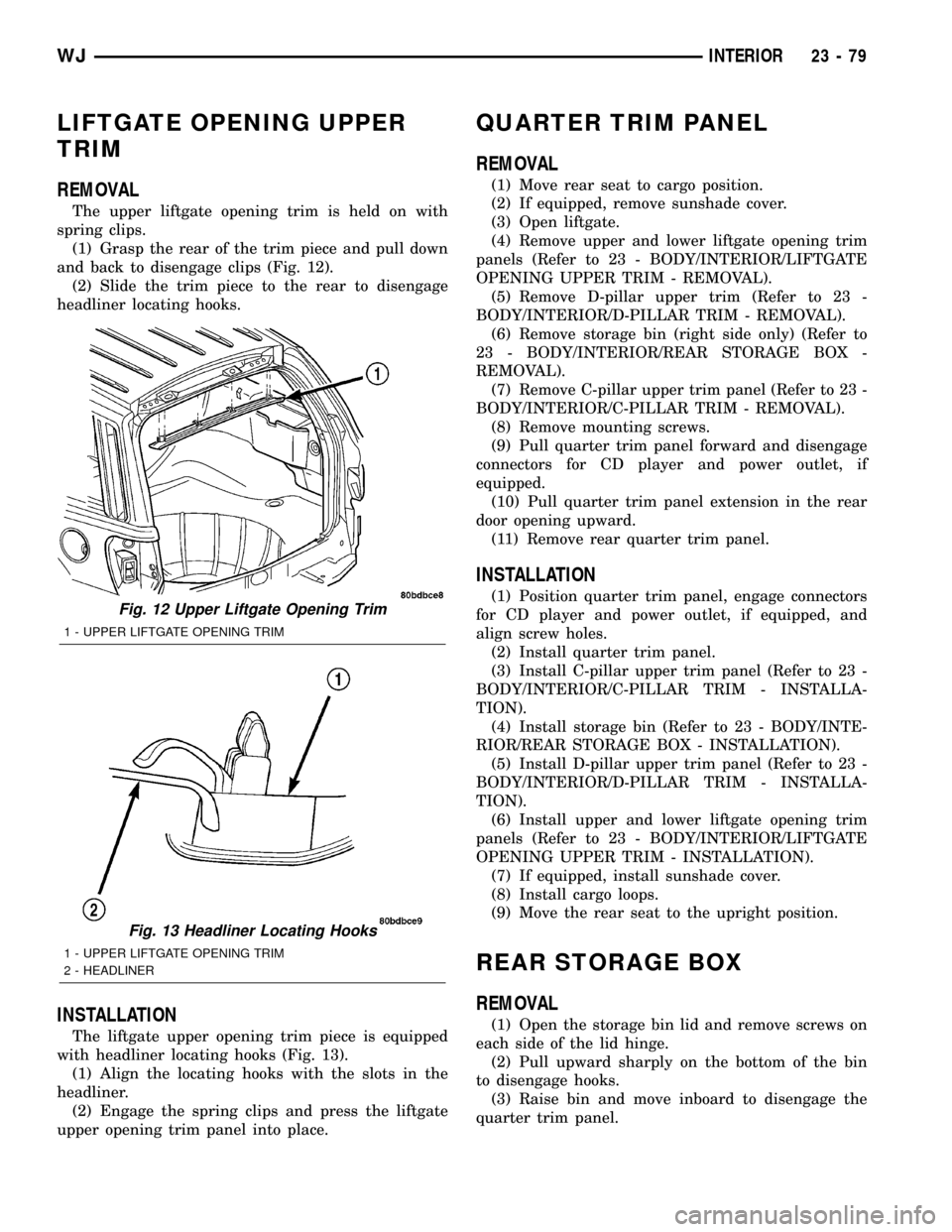
(1) Grasp the rear of the trim piece and pull down
and back to disengage clips (Fig. 12).
(2) Slide the trim piece to the rear to disengage
headliner locating hooks.
INSTALLATION
The liftgate upper opening trim piece is equipped
with headliner locating hooks (Fig. 13).
(1) Align the locating hooks with the slots in the
headliner.
(2) Engage the spring clips and press the liftgate
upper opening trim panel into place.
QUARTER TRIM PANEL
REMOVAL
(1) Move rear seat to cargo position.
(2) If equipped, remove sunshade cover.
(3) Open liftgate.
(4) Remove upper and lower liftgate opening trim
panels (Refer to 23 - BODY/INTERIOR/LIFTGATE
OPENING UPPER TRIM - REMOVAL).
(5) Remove D-pillar upper trim (Refer to 23 -
BODY/INTERIOR/D-PILLAR TRIM - REMOVAL).
(6) Remove storage bin (right side only) (Refer to
23 - BODY/INTERIOR/REAR STORAGE BOX -
REMOVAL).
(7) Remove C-pillar upper trim panel (Refer to 23 -
BODY/INTERIOR/C-PILLAR TRIM - REMOVAL).
(8) Remove mounting screws.
(9) Pull quarter trim panel forward and disengage
connectors for CD player and power outlet, if
equipped.
(10) Pull quarter trim panel extension in the rear
door opening upward.
(11) Remove rear quarter trim panel.
INSTALLATION
(1) Position quarter trim panel, engage connectors
for CD player and power outlet, if equipped, and
align screw holes.
(2) Install quarter trim panel.
(3) Install C-pillar upper trim panel (Refer to 23 -
BODY/INTERIOR/C-PILLAR TRIM - INSTALLA-
TION).
(4) Install storage bin (Refer to 23 - BODY/INTE-
RIOR/REAR STORAGE BOX - INSTALLATION).
(5) Install D-pillar upper trim panel (Refer to 23 -
BODY/INTERIOR/D-PILLAR TRIM - INSTALLA-
TION).
(6) Install upper and lower liftgate opening trim
panels (Refer to 23 - BODY/INTERIOR/LIFTGATE
OPENING UPPER TRIM - INSTALLATION).
(7) If equipped, install sunshade cover.
(8) Install cargo loops.
(9) Move the rear seat to the upright position.
REAR STORAGE BOX
REMOVAL
(1) Open the storage bin lid and remove screws on
each side of the lid hinge.
(2) Pull upward sharply on the bottom of the bin
to disengage hooks.
(3) Raise bin and move inboard to disengage the
quarter trim panel.
Fig. 12 Upper Liftgate Opening Trim
1 - UPPER LIFTGATE OPENING TRIM
Fig. 13 Headliner Locating Hooks
1 - UPPER LIFTGATE OPENING TRIM
2 - HEADLINER
WJINTERIOR 23 - 79
Page 1966 of 2199

STATIONARY GLASS
TABLE OF CONTENTS
page page
DOOR GLASS
REMOVAL.............................93
INSTALLATION.........................93
QUARTER WINDOW
REMOVAL.............................93INSTALLATION.........................93
WINDSHIELD
REMOVAL.............................94
INSTALLATION.........................95
DOOR GLASS
REMOVAL
(1) Remove door trim panel.
(2) Remove waterdam.
(3) Remove inner belt weatherstrip.
(4) Remove bolt attaching bottom of rear glass run
channel to door.
(5) Pull run channel downward and separate from
door.
(6) Remove screws attaching stationary door glass
frame to door (Fig. 1) and (Fig. 2).
(7) Separate stationary door glass from door.
INSTALLATION
(1) Position stationary door glass in door.
(2) Install screws attaching stationary door glass
frame to door.
(3) Install glass run channel.
(4) Install inner belt weatherstrip.
(5) Install waterdam.
(6) Install door trim panel.
QUARTER WINDOW
REMOVAL
(1) Cut urethane bonding from around quarter
window glass using a suitable sharp cold knife. A
pneumatic cutting device can be used if available.
(2) Separate glass from vehicle.
INSTALLATION
CAUTION: Open a window before installing glass.
This will avoid pressurizing the passenger compart-
ment. If a door or liftgate is slammed before ure-
thane is cured, water leaks can result.
The window opening fence should be cleaned of old
urethane bonding material.
(1) Clean inside of glass with Mopar Glass Cleaner
and lint-free cloth.
(2) Apply PVC (vinyl) primer 25 mm (1 in.) wide
around edge of glass. Wipe with clean/dry lint-free
cloth.
Fig. 1 Stationary Door Glass
1 - DOOR
2 - STATIONARY DOOR GLASS
Fig. 2 Stationary Door Glass
1 - STATIONARY DOOR GLASS
2 - DOOR
WJSTATIONARY GLASS 23 - 93