2002 JEEP GRAND CHEROKEE length
[x] Cancel search: lengthPage 1258 of 2199
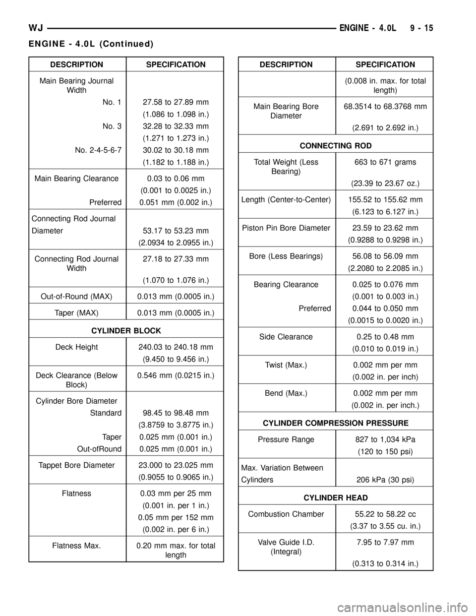
DESCRIPTION SPECIFICATION
Main Bearing Journal
Width
No. 1 27.58 to 27.89 mm
(1.086 to 1.098 in.)
No. 3 32.28 to 32.33 mm
(1.271 to 1.273 in.)
No. 2-4-5-6-7 30.02 to 30.18 mm
(1.182 to 1.188 in.)
Main Bearing Clearance 0.03 to 0.06 mm
(0.001 to 0.0025 in.)
Preferred 0.051 mm (0.002 in.)
Connecting Rod Journal
Diameter 53.17 to 53.23 mm
(2.0934 to 2.0955 in.)
Connecting Rod Journal
Width27.18 to 27.33 mm
(1.070 to 1.076 in.)
Out-of-Round (MAX) 0.013 mm (0.0005 in.)
Taper (MAX) 0.013 mm (0.0005 in.)
CYLINDER BLOCK
Deck Height 240.03 to 240.18 mm
(9.450 to 9.456 in.)
Deck Clearance (Below
Block)0.546 mm (0.0215 in.)
Cylinder Bore Diameter
Standard 98.45 to 98.48 mm
(3.8759 to 3.8775 in.)
Taper 0.025 mm (0.001 in.)
Out-ofRound 0.025 mm (0.001 in.)
Tappet Bore Diameter 23.000 to 23.025 mm
(0.9055 to 0.9065 in.)
Flatness 0.03 mm per 25 mm
(0.001 in. per 1 in.)
0.05 mm per 152 mm
(0.002 in. per 6 in.)
Flatness Max. 0.20 mm max. for total
lengthDESCRIPTION SPECIFICATION
(0.008 in. max. for total
length)
Main Bearing Bore
Diameter68.3514 to 68.3768 mm
(2.691 to 2.692 in.)
CONNECTING ROD
Total Weight (Less
Bearing)663 to 671 grams
(23.39 to 23.67 oz.)
Length (Center-to-Center) 155.52 to 155.62 mm
(6.123 to 6.127 in.)
Piston Pin Bore Diameter 23.59 to 23.62 mm
(0.9288 to 0.9298 in.)
Bore (Less Bearings) 56.08 to 56.09 mm
(2.2080 to 2.2085 in.)
Bearing Clearance 0.025 to 0.076 mm
(0.001 to 0.003 in.)
Preferred 0.044 to 0.050 mm
(0.0015 to 0.0020 in.)
Side Clearance 0.25 to 0.48 mm
(0.010 to 0.019 in.)
Twist (Max.) 0.002 mm per mm
(0.002 in. per inch)
Bend (Max.) 0.002 mm per mm
(0.002 in. per inch.)
CYLINDER COMPRESSION PRESSURE
Pressure Range 827 to 1,034 kPa
(120 to 150 psi)
Max. Variation Between
Cylinders 206 kPa (30 psi)
CYLINDER HEAD
Combustion Chamber 55.22 to 58.22 cc
(3.37 to 3.55 cu. in.)
Valve Guide I.D.
(Integral)7.95 to 7.97 mm
(0.313 to 0.314 in.)
WJENGINE - 4.0L 9 - 15
ENGINE - 4.0L (Continued)
Page 1259 of 2199
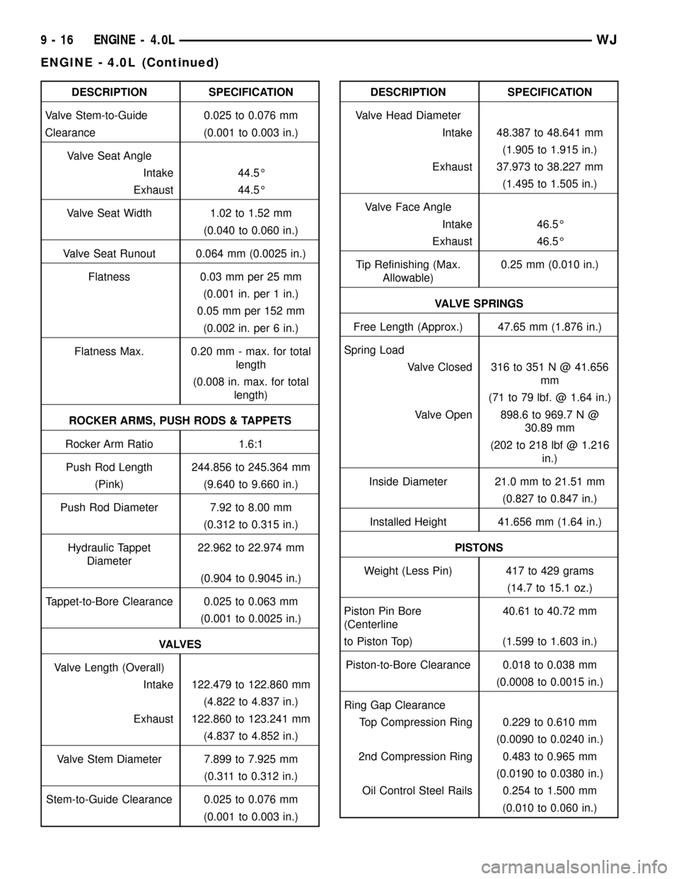
DESCRIPTION SPECIFICATION
Valve Stem-to-Guide 0.025 to 0.076 mm
Clearance (0.001 to 0.003 in.)
Valve Seat Angle
Intake 44.5É
Exhaust 44.5É
Valve Seat Width 1.02 to 1.52 mm
(0.040 to 0.060 in.)
Valve Seat Runout 0.064 mm (0.0025 in.)
Flatness 0.03 mm per 25 mm
(0.001 in. per 1 in.)
0.05 mm per 152 mm
(0.002 in. per 6 in.)
Flatness Max. 0.20 mm - max. for total
length
(0.008 in. max. for total
length)
ROCKER ARMS, PUSH RODS & TAPPETS
Rocker Arm Ratio 1.6:1
Push Rod Length 244.856 to 245.364 mm
(Pink) (9.640 to 9.660 in.)
Push Rod Diameter 7.92 to 8.00 mm
(0.312 to 0.315 in.)
Hydraulic Tappet
Diameter22.962 to 22.974 mm
(0.904 to 0.9045 in.)
Tappet-to-Bore Clearance 0.025 to 0.063 mm
(0.001 to 0.0025 in.)
VA LV E S
Valve Length (Overall)
Intake 122.479 to 122.860 mm
(4.822 to 4.837 in.)
Exhaust 122.860 to 123.241 mm
(4.837 to 4.852 in.)
Valve Stem Diameter 7.899 to 7.925 mm
(0.311 to 0.312 in.)
Stem-to-Guide Clearance 0.025 to 0.076 mm
(0.001 to 0.003 in.)DESCRIPTION SPECIFICATION
Valve Head Diameter
Intake 48.387 to 48.641 mm
(1.905 to 1.915 in.)
Exhaust 37.973 to 38.227 mm
(1.495 to 1.505 in.)
Valve Face Angle
Intake 46.5É
Exhaust 46.5É
Tip Refinishing (Max.
Allowable)0.25 mm (0.010 in.)
VALVE SPRINGS
Free Length (Approx.) 47.65 mm (1.876 in.)
Spring Load
Valve Closed 316 to 351 N @ 41.656
mm
(71 to 79 lbf. @ 1.64 in.)
Valve Open 898.6 to 969.7 N @
30.89 mm
(202 to 218 lbf @ 1.216
in.)
Inside Diameter 21.0 mm to 21.51 mm
(0.827 to 0.847 in.)
Installed Height 41.656 mm (1.64 in.)
PISTONS
Weight (Less Pin) 417 to 429 grams
(14.7 to 15.1 oz.)
Piston Pin Bore
(Centerline40.61 to 40.72 mm
to Piston Top) (1.599 to 1.603 in.)
Piston-to-Bore Clearance 0.018 to 0.038 mm
(0.0008 to 0.0015 in.)
Ring Gap Clearance
Top Compression Ring 0.229 to 0.610 mm
(0.0090 to 0.0240 in.)
2nd Compression Ring 0.483 to 0.965 mm
(0.0190 to 0.0380 in.)
Oil Control Steel Rails 0.254 to 1.500 mm
(0.010 to 0.060 in.)
9 - 16 ENGINE - 4.0LWJ
ENGINE - 4.0L (Continued)
Page 1267 of 2199
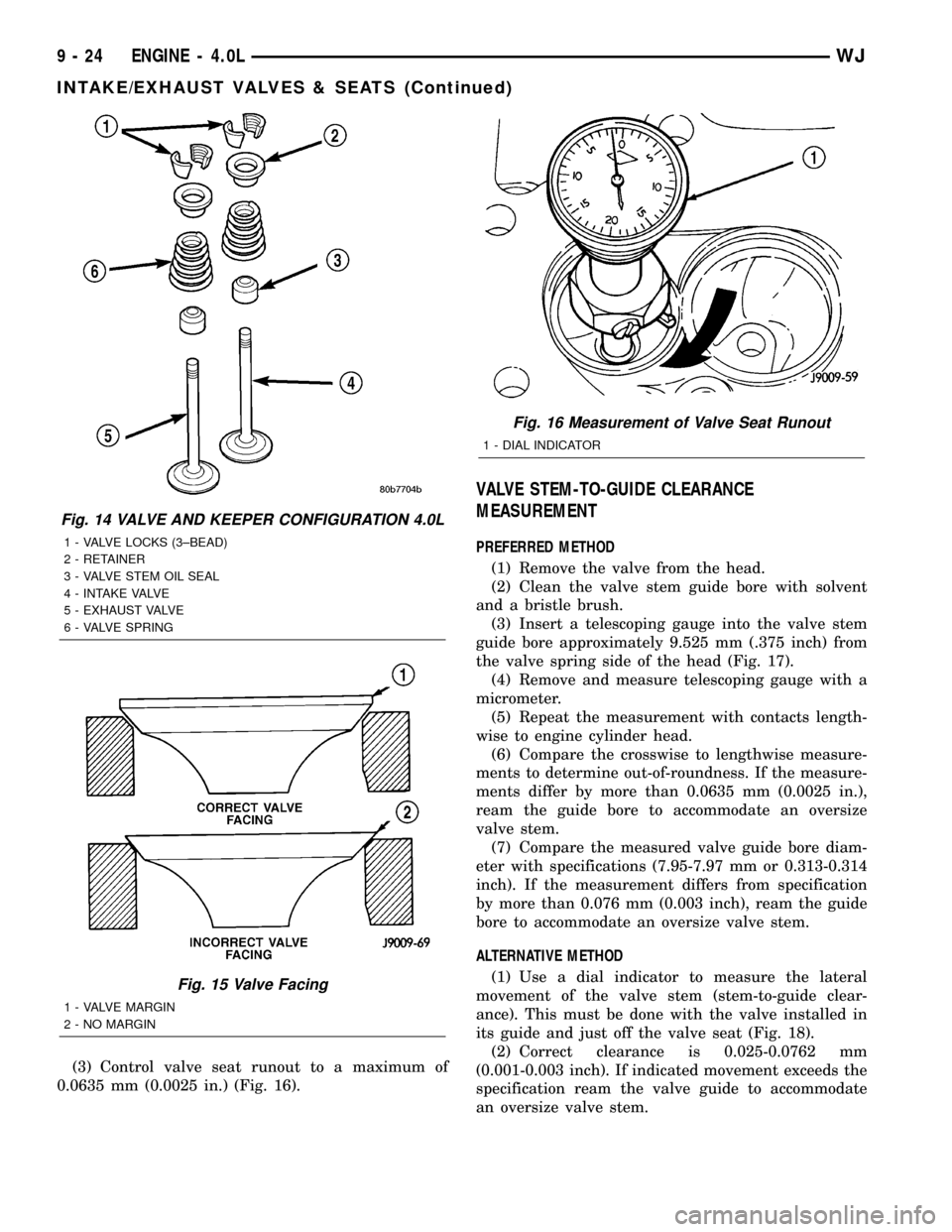
(3) Control valve seat runout to a maximum of
0.0635 mm (0.0025 in.) (Fig. 16).
VALVE STEM-TO-GUIDE CLEARANCE
MEASUREMENT
PREFERRED METHOD
(1) Remove the valve from the head.
(2) Clean the valve stem guide bore with solvent
and a bristle brush.
(3) Insert a telescoping gauge into the valve stem
guide bore approximately 9.525 mm (.375 inch) from
the valve spring side of the head (Fig. 17).
(4) Remove and measure telescoping gauge with a
micrometer.
(5) Repeat the measurement with contacts length-
wise to engine cylinder head.
(6) Compare the crosswise to lengthwise measure-
ments to determine out-of-roundness. If the measure-
ments differ by more than 0.0635 mm (0.0025 in.),
ream the guide bore to accommodate an oversize
valve stem.
(7) Compare the measured valve guide bore diam-
eter with specifications (7.95-7.97 mm or 0.313-0.314
inch). If the measurement differs from specification
by more than 0.076 mm (0.003 inch), ream the guide
bore to accommodate an oversize valve stem.
ALTERNATIVE METHOD
(1) Use a dial indicator to measure the lateral
movement of the valve stem (stem-to-guide clear-
ance). This must be done with the valve installed in
its guide and just off the valve seat (Fig. 18).
(2) Correct clearance is 0.025-0.0762 mm
(0.001-0.003 inch). If indicated movement exceeds the
specification ream the valve guide to accommodate
an oversize valve stem.
Fig. 14 VALVE AND KEEPER CONFIGURATION 4.0L
1 - VALVE LOCKS (3±BEAD)
2 - RETAINER
3 - VALVE STEM OIL SEAL
4 - INTAKE VALVE
5 - EXHAUST VALVE
6 - VALVE SPRING
Fig. 15 Valve Facing
1 - VALVE MARGIN
2 - NO MARGIN
Fig. 16 Measurement of Valve Seat Runout
1 - DIAL INDICATOR
9 - 24 ENGINE - 4.0LWJ
INTAKE/EXHAUST VALVES & SEATS (Continued)
Page 1270 of 2199
INSPECTION
Inspect the pivot surface area of each rocker arm.
Replace any that are scuffed, pitted, cracked or
excessively worn.
Inspect the valve stem tip contact surface of each
rocker arm and replace any rocker arm that is deeply
pitted.
Inspect each push rod end for excessive wear and
replace as required. If any push rod is excessively
worn because of lack of oil, replace it and inspect the
corresponding hydraulic tappet for excessive wear.
Inspect the push rods for straightness by rolling
them on a flat surface or by shining a light between
the push rod and the flat surface.
A wear pattern along the length of the push rod is
not normal. Inspect the engine cylinder head for
obstruction if this condition exists.
INSTALLATION
NOTE: This procedure can be done with the engine
in or out of the vehicle.
(1) Lubricate the ball ends of the push rods with
MopartEngine Oil Supplement, or equivalent and
install push rods in their original locations. Ensurethat the bottom end of each push rod is centered in
the tappet plunger cap seat.
(2) Using MopartEngine Oil Supplement, or
equivalent, lubricate the area of the rocker arm that
the pivot contacts. Install rocker arms, pivots and
bridge above each cylinder in their originally position
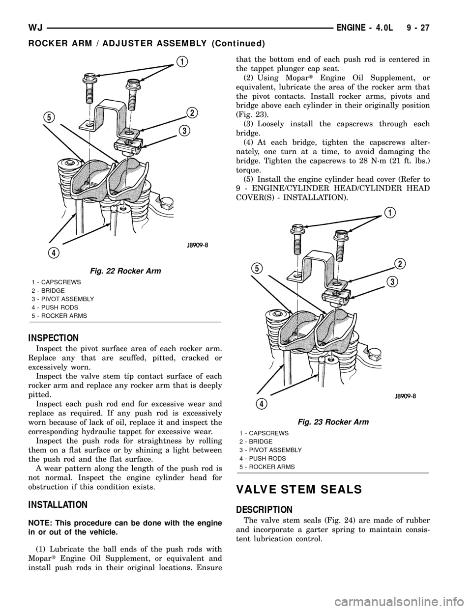
(Fig. 23).
(3) Loosely install the capscrews through each
bridge.
(4) At each bridge, tighten the capscrews alter-
nately, one turn at a time, to avoid damaging the
bridge. Tighten the capscrews to 28 N´m (21 ft. lbs.)
torque.
(5) Install the engine cylinder head cover (Refer to
9 - ENGINE/CYLINDER HEAD/CYLINDER HEAD
COVER(S) - INSTALLATION).
VALVE STEM SEALS
DESCRIPTION
The valve stem seals (Fig. 24) are made of rubber
and incorporate a garter spring to maintain consis-
tent lubrication control.
Fig. 22 Rocker Arm
1 - CAPSCREWS
2 - BRIDGE
3 - PIVOT ASSEMBLY
4 - PUSH RODS
5 - ROCKER ARMS
Fig. 23 Rocker Arm
1 - CAPSCREWS
2 - BRIDGE
3 - PIVOT ASSEMBLY
4 - PUSH RODS
5 - ROCKER ARMS
WJENGINE - 4.0L 9 - 27
ROCKER ARM / ADJUSTER ASSEMBLY (Continued)
Page 1293 of 2199
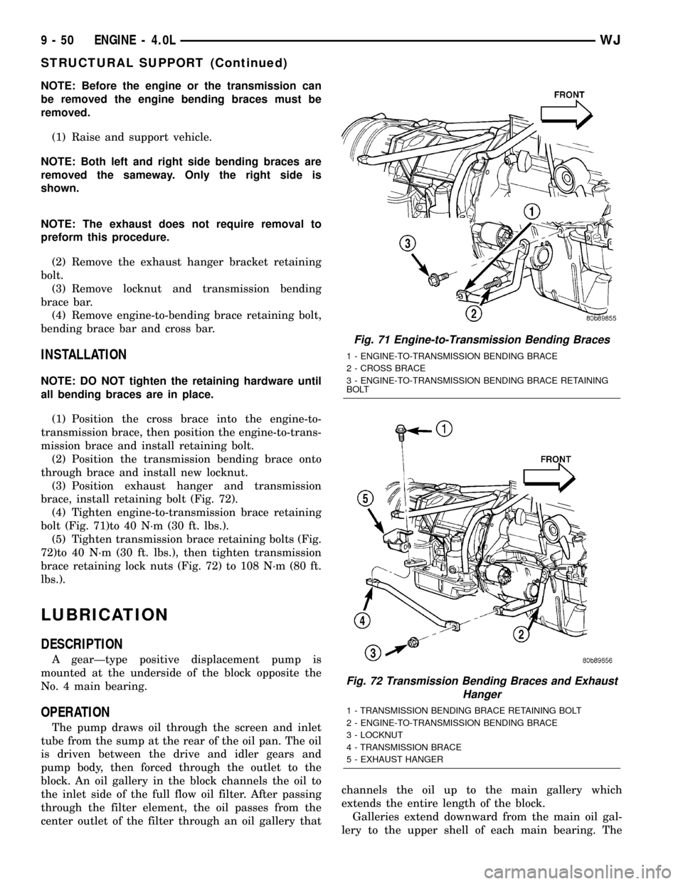
NOTE: Before the engine or the transmission can
be removed the engine bending braces must be
removed.
(1) Raise and support vehicle.
NOTE: Both left and right side bending braces are
removed the sameway. Only the right side is
shown.
NOTE: The exhaust does not require removal to
preform this procedure.
(2) Remove the exhaust hanger bracket retaining
bolt.
(3) Remove locknut and transmission bending
brace bar.
(4) Remove engine-to-bending brace retaining bolt,
bending brace bar and cross bar.
INSTALLATION
NOTE: DO NOT tighten the retaining hardware until
all bending braces are in place.
(1) Position the cross brace into the engine-to-
transmission brace, then position the engine-to-trans-
mission brace and install retaining bolt.
(2) Position the transmission bending brace onto
through brace and install new locknut.
(3) Position exhaust hanger and transmission
brace, install retaining bolt (Fig. 72).
(4) Tighten engine-to-transmission brace retaining
bolt (Fig. 71)to 40 N´m (30 ft. lbs.).
(5) Tighten transmission brace retaining bolts (Fig.
72)to 40 N´m (30 ft. lbs.), then tighten transmission
brace retaining lock nuts (Fig. 72) to 108 N´m (80 ft.
lbs.).
LUBRICATION
DESCRIPTION
A gearÐtype positive displacement pump is
mounted at the underside of the block opposite the
No. 4 main bearing.
OPERATION
The pump draws oil through the screen and inlet
tube from the sump at the rear of the oil pan. The oil
is driven between the drive and idler gears and
pump body, then forced through the outlet to the
block. An oil gallery in the block channels the oil to
the inlet side of the full flow oil filter. After passing
through the filter element, the oil passes from the
center outlet of the filter through an oil gallery thatchannels the oil up to the main gallery which
extends the entire length of the block.
Galleries extend downward from the main oil gal-
lery to the upper shell of each main bearing. The
Fig. 71 Engine-to-Transmission Bending Braces
1 - ENGINE-TO-TRANSMISSION BENDING BRACE
2 - CROSS BRACE
3 - ENGINE-TO-TRANSMISSION BENDING BRACE RETAINING
BOLT
Fig. 72 Transmission Bending Braces and Exhaust
Hanger
1 - TRANSMISSION BENDING BRACE RETAINING BOLT
2 - ENGINE-TO-TRANSMISSION BENDING BRACE
3 - LOCKNUT
4 - TRANSMISSION BRACE
5 - EXHAUST HANGER
9 - 50 ENGINE - 4.0LWJ
STRUCTURAL SUPPORT (Continued)
Page 1319 of 2199
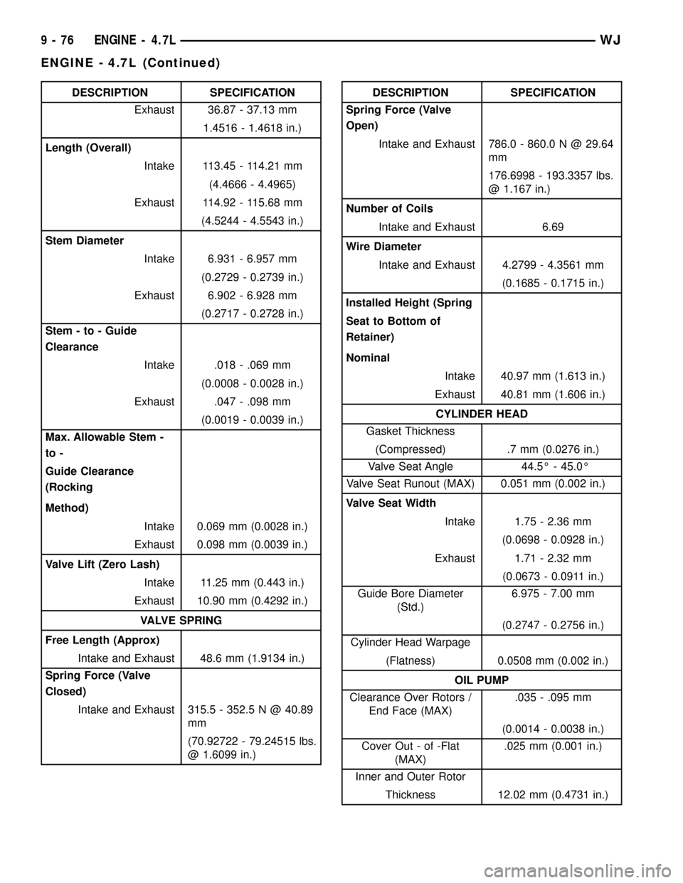
DESCRIPTION SPECIFICATION
Exhaust 36.87 - 37.13 mm
1.4516 - 1.4618 in.)
Length (Overall)
Intake 113.45 - 114.21 mm
(4.4666 - 4.4965)
Exhaust 114.92 - 115.68 mm
(4.5244 - 4.5543 in.)
Stem Diameter
Intake 6.931 - 6.957 mm
(0.2729 - 0.2739 in.)
Exhaust 6.902 - 6.928 mm
(0.2717 - 0.2728 in.)
Stem - to - Guide
Clearance
Intake .018 - .069 mm
(0.0008 - 0.0028 in.)
Exhaust .047 - .098 mm
(0.0019 - 0.0039 in.)
Max. Allowable Stem -
to -
Guide Clearance
(Rocking
Method)
Intake 0.069 mm (0.0028 in.)
Exhaust 0.098 mm (0.0039 in.)
Valve Lift (Zero Lash)
Intake 11.25 mm (0.443 in.)
Exhaust 10.90 mm (0.4292 in.)
VALVE SPRING
Free Length (Approx)
Intake and Exhaust 48.6 mm (1.9134 in.)
Spring Force (Valve
Closed)
Intake and Exhaust 315.5 - 352.5 N @ 40.89
mm
(70.92722 - 79.24515 lbs.
@ 1.6099 in.)DESCRIPTION SPECIFICATION
Spring Force (Valve
Open)
Intake and Exhaust 786.0 - 860.0 N @ 29.64
mm
176.6998 - 193.3357 lbs.
@ 1.167 in.)
Number of Coils
Intake and Exhaust 6.69
Wire Diameter
Intake and Exhaust 4.2799 - 4.3561 mm
(0.1685 - 0.1715 in.)
Installed Height (Spring
Seat to Bottom of
Retainer)
Nominal
Intake 40.97 mm (1.613 in.)
Exhaust 40.81 mm (1.606 in.)
CYLINDER HEAD
Gasket Thickness
(Compressed) .7 mm (0.0276 in.)
Valve Seat Angle 44.5É - 45.0É
Valve Seat Runout (MAX) 0.051 mm (0.002 in.)
Valve Seat Width
Intake 1.75 - 2.36 mm
(0.0698 - 0.0928 in.)
Exhaust 1.71 - 2.32 mm
(0.0673 - 0.0911 in.)
Guide Bore Diameter
(Std.)6.975 - 7.00 mm
(0.2747 - 0.2756 in.)
Cylinder Head Warpage
(Flatness) 0.0508 mm (0.002 in.)
OIL PUMP
Clearance Over Rotors /
End Face (MAX).035 - .095 mm
(0.0014 - 0.0038 in.)
Cover Out - of -Flat
(MAX).025 mm (0.001 in.)
Inner and Outer Rotor
Thickness 12.02 mm (0.4731 in.)
9 - 76 ENGINE - 4.7LWJ
ENGINE - 4.7L (Continued)
Page 1321 of 2199
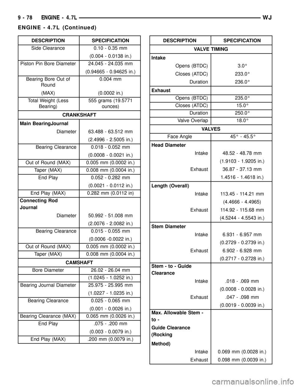
DESCRIPTION SPECIFICATION
Side Clearance 0.10 - 0.35 mm
(0.004 - 0.0138 in.)
Piston Pin Bore Diameter 24.045 - 24.035 mm
(0.94665 - 0.94625 in.)
Bearing Bore Out of
Round0.004 mm
(MAX) (0.0002 in.)
Total Weight (Less
Bearing)555 grams (19.5771
ounces)
CRANKSHAFT
Main BearingJournal
Diameter 63.488 - 63.512 mm
(2.4996 - 2.5005 in.)
Bearing Clearance 0.018 - 0.052 mm
(0.0008 - 0.0021 in.)
Out of Round (MAX) 0.005 mm (0.0002 in.)
Taper (MAX) 0.008 mm (0.0004 in.)
End Play 0.052 - 0.282 mm
(0.0021 - 0.0112 in.)
End Play (MAX) 0.282 mm (0.0112 in)
Connecting Rod
Journal
Diameter 50.992 - 51.008 mm
(2.0076 - 2.0082 in.)
Bearing Clearance 0.015 - 0.055 mm
(0.0006 -0.0022 in.)
Out of Round (MAX) 0.005 mm (0.0002 in.)
Taper (MAX) 0.008 mm (0.0004 in.)
CAMSHAFT
Bore Diameter 26.02 - 26.04 mm
(1.0245 - 1.0252 in.)
Bearing Journal Diameter 25.975 - 25.995 mm
(1.0227 - 1.0235 in.)
Bearing Clearance 0.025 - 0.065 mm
(0.001 - 0.0026 in.)
Bearing Clearance (MAX) 0.065 mm (0.0026 in.)
End Play .075 - .200 mm
(0.003 - 0.0079 in.)
End Play (MAX) .200 mm (0.0079 in.)DESCRIPTION SPECIFICATION
VALVE TIMING
Intake
Opens (BTDC) 3.0É
Closes (ATDC) 233.0É
Duration 236.0É
Exhaust
Opens (BTDC) 235.0É
Closes (ATDC) 15.0É
Duration 250.0É
Valve Overlap 18.0É
VA LV E S
Face Angle 45É - 45.5É
Head Diameter
Intake 48.52 - 48.78 mm
(1.9103 - 1.9205 in.)
Exhaust 36.87 - 37.13 mm
1.4516 - 1.4618 in.)
Length (Overall)
Intake 113.45 - 114.21 mm
(4.4666 - 4.4965)
Exhaust 114.92 - 115.68 mm
(4.5244 - 4.5543 in.)
Stem Diameter
Intake 6.931 - 6.957 mm
(0.2729 - 0.2739 in.)
Exhaust 6.902 - 6.928 mm
(0.2717 - 0.2728 in.)
Stem - to - Guide
Clearance
Intake .018 - .069 mm
(0.0008 - 0.0028 in.)
Exhaust .047 - .098 mm
(0.0019 - 0.0039 in.)
Max. Allowable Stem -
to -
Guide Clearance
(Rocking
Method)
Intake 0.069 mm (0.0028 in.)
Exhaust 0.098 mm (0.0039 in.)
9 - 78 ENGINE - 4.7LWJ
ENGINE - 4.7L (Continued)
Page 1322 of 2199
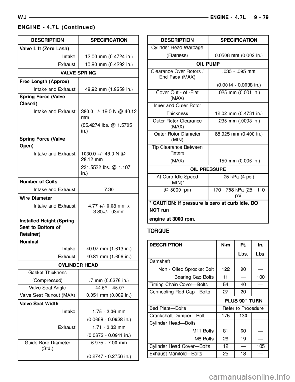
DESCRIPTION SPECIFICATION
Valve Lift (Zero Lash)
Intake 12.00 mm (0.4724 in.)
Exhaust 10.90 mm (0.4292 in.)
VALVE SPRING
Free Length (Approx)
Intake and Exhaust 48.92 mm (1.9259 in.)
Spring Force (Valve
Closed)
Intake and Exhaust 380.0 +/- 19.0 N @ 40.12
mm
(85.4274 lbs. @ 1.5795
in.)
Spring Force (Valve
Open)
Intake and Exhaust 1030.0 +/- 46.0 N @
28.12 mm
231.5532 lbs. @ 1.107
in.)
Number of Coils
Intake and Exhaust 7.30
Wire Diameter
Intake and Exhaust 4.77 +/- 0.03 mm x
3.80+/- .03mm
Installed Height (Spring
Seat to Bottom of
Retainer)
Nominal
Intake 40.97 mm (1.613 in.)
Exhaust 40.81 mm (1.606 in.)
CYLINDER HEAD
Gasket Thickness
(Compressed) .7 mm (0.0276 in.)
Valve Seat Angle 44.5É - 45.0É
Valve Seat Runout (MAX) 0.051 mm (0.002 in.)
Valve Seat Width
Intake 1.75 - 2.36 mm
(0.0698 - 0.0928 in.)
Exhaust 1.71 - 2.32 mm
(0.0673 - 0.0911 in.)
Guide Bore Diameter
(Std.)6.975 - 7.00 mm
(0.2747 - 0.2756 in.)DESCRIPTION SPECIFICATION
Cylinder Head Warpage
(Flatness) 0.0508 mm (0.002 in.)
OIL PUMP
Clearance Over Rotors /
End Face (MAX).035 - .095 mm
(0.0014 - 0.0038 in.)
Cover Out - of -Flat
(MAX).025 mm (0.001 in.)
Inner and Outer Rotor
Thickness 12.02 mm (0.4731 in.)
Outer Rotor Clearance
(MAX).235 mm (.0093 in.)
Outer Rotor Diameter
(MIN)85.925 mm (0.400 in.)
Tip Clearance Between
Rotors
(MAX) .150 mm (0.006 in.)
OIL PRESSURE
At Curb Idle Speed
(MIN)*25 kPa (4 psi)
@ 3000 rpm 170 - 758 kPa (25 - 110
psi)
* CAUTION: If pressure is zero at curb idle, DO
NOT run
engine at 3000 rpm.
TORQUE
DESCRIPTION N´m Ft. In.
Lbs. Lbs.
Camshaft
Non - Oiled Sprocket Bolt 122 90 Ð
Bearing Cap Bolts 11 Ð 100
Timing Chain CoverÐBolts 54 40 Ð
Connecting Rod CapÐBolts 27 20 Ð
PLUS 90É TURN
Bed PlateÐBolts Refer to Procedure
Crankshaft DamperÐBolt 175 130 Ð
Cylinder HeadÐBolts
M11 Bolts 81 60 Ð
M8 Bolts 26 19 Ð
Cylinder Head CoverÐBolts 12 Ð 105
Exhaust ManifoldÐBolts 25 18 Ð
WJENGINE - 4.7L 9 - 79
ENGINE - 4.7L (Continued)