2002 JEEP GRAND CHEROKEE front suspension
[x] Cancel search: front suspensionPage 392 of 2199

CONDITION POSSIBLE CAUSES CORRECTION
HORN SOUNDS
CONTINUOUSLY1. Faulty horn relay. 1. Refer to Horn Relay for the proper horn relay
diagnosis and testing procedures. Replace the
horn relay or repair the shorted horn relay control
circuit, if required.
2. Faulty horn switch. 2. Refer to Horn Switch for the proper horn switch
diagnosis and testing procedures. Replace the
horn switch or repair the shorted horn switch
circuit, if required.
HORN
DESCRIPTION
The dual electromagnetic diaphragm-type horns
are standard equipment on this model. Both horns
are secured to a mounting bracket. The mounting
bracket is secured with a screw to the back side of
the right extension of the radiator closure assembly,
just ahead of the right front wheel house and below
the front wheel house extension. The two horns are
connected in parallel. Each horn is grounded through
its wire harness connector and circuit to an eyelet
secured to the right inner fender shield near the bat-
tery, and receives battery feed through the closed
contacts of the horn relay.
The horns cannot be repaired or adjusted and, if
faulty or damaged, they must be individually
replaced.
OPERATION
Within the two halves of the molded plastic horn
housing are a flexible diaphragm, a plunger, an elec-
tromagnetic coil and a set of contact points. The dia-
phragm is secured in suspension around its
perimeter by the mating surfaces of the horn hous-
ing. The plunger is secured to the center of the dia-
phragm and extends into the center of the
electromagnet. The contact points control the current
flow through the electromagnet.
When the horn is energized, electrical current
flows through the closed contact points to the electro-
magnet. The resulting electromagnetic field draws
the plunger and diaphragm toward it until that
movement mechanically opens the contact points.
When the contact points open, the electromagnetic
field collapses allowing the plunger and diaphragm to
return to their relaxed positions and closing the con-
tact points again. This cycle continues repeating at a
very rapid rate producing the vibration and move-
ment of air that creates the sound that is directed
through the horn outlet.
DIAGNOSIS AND TESTING - HORN
Refer to the appropriate wiring information. The
wiring information includes wiring diagrams, proper
wire and connector repair procedures, details of wire
harness routing and retention, connector pin-out
information and location views for the various wire
harness connectors, splices and grounds.
(1) Disconnect the wire harness connector(s) from
the horn connector receptacle(s). Measure the resis-
tance between the ground circuit cavity of the horn(s)
wire harness connector(s) and a good ground. There
should be no measurable resistance. If OK, go to Step
2. If not OK, repair the open ground circuit to ground
as required.
(2) Check for battery voltage at the horn relay out-
put circuit cavity of the horn(s) wire harness connec-
tor(s). There should be zero volts. If OK, go to Step 3.
If not OK, repair the shorted horn relay output cir-
cuit or replace the faulty horn relay as required.
(3) Depress the horn switch. There should now be
battery voltage at the horn relay output circuit cavity
of the horn(s) wire harness connector(s). If OK,
replace the faulty horns. If not OK, repair the open
horn relay output circuit to the horn relay as
required.
REMOVAL
(1) Disconnect and isolate the battery negative
cable.
(2) Raise and support the vehicle.
(3) Remove the lower front half of the inner liner
from the right front fender wheel house. (Refer to 23
- BODY/EXTERIOR/FRONT FENDER - REMOVAL).
(4) Reach through the front of the right front
fender wheel house opening to access and disconnect
the two right headlamp and dash wire harness con-
nectors from the horn connector receptacles (Fig. 1).
Be certain to disengage the connector lock tabs
before disconnecting them from the horn connector
receptacles.
(5) Remove the screw that secures the horn
mounting bracket to the right extension of the radi-
ator closure assembly.
WJHORN 8H - 3
HORN SYSTEM (Continued)
Page 468 of 2199

(from rear of vehicle forward) to verify accuracy of
the line placement.
(4) Rock vehicle side-to-side three times to allow
suspension to stabilize.
(5) Jounce front suspension three times by pushing
downward on front bumper and releasing.
(6) Measure the distance from the center of head-
lamp lens to the floor. Transfer measurement to the
alignment screen (with tape). Use this line for
up/down adjustment reference.
(7) Measure distance from the centerline of the
vehicle to the center of each headlamp being aligned.
Transfer measurements to screen (with tape) to each
side of vehicle centerline. Use these lines for left/
right adjustment reference.
HEADLAMP ADJUSTMENT
A properly aimed low beam will project the top
edge of the beam intensity pattern on the screen
from 25 mm (1 in.) above to 75 mm (3 in.) below
headlamp centerline. The side-to-side left edge of the
beam intensity pattern should be from 50 mm (2 in.)
left to 50 mm (2 in.) right of headlamp centerline
(Fig. 17).
(1) Clean front of the headlamps.
(2) Place headlamps on LOW beam.(3) Cover front of the headlamp that is not being
adjusted.
(4) Turn adjustment screw (Fig. 18) and (Fig. 19)
until the top edge of the beam intensity pattern is
positioned within 25 mm (1 in.) above or 75 mm (3
in.) below the headlamp horizontal centerline.
(5) Cover front of the headlamp and adjust the
other headlamp beam as instructed below.
(6) Rotate the adjustment screw until the top edge
of the beam intensity pattern is positioned within 25
mm (1 in.) above or 75 mm (3 in.) below the head-
lamp horizontal centerline.
LICENSE PLATE LAMP
REMOVAL
REMOVAL - BULB
(1) Remove lamp assembly from liftgate lamp mod-
ule.
(2) Rotate bulb socket counterclockwise to discon-
nect bulb socket from lamp.
(3) Remove bulb from socket.
Fig. 16 Headlamp Alignment ScreenÐTypical
1 - CENTER OF VEHICLE TO CENTER OF HEADLAMP LENS
2 - FLOOR TO CENTER OF HEADLAMP LENS
3 - 7.62 METERS (25 FEET)4 - FRONT OF HEADLAMP
5 - VEHICLE CENTERLINE
WJLAMPS/LIGHTING - EXTERIOR 8L - 17
HEADLAMP UNIT (Continued)
Page 635 of 2199

(3) Disconnect the two washer reservoir washer
hoses from the two engine compartment washer
hoses at the inline connectors located on the top of
the left front fender wheel house (Fig. 23).
(4) Open the washer reservoir filler cap and
unsnap the filler cap hinge from the hook on the
filler neck.
(5) Remove the one screw that secures the washer
reservoir filler neck to the left inner fender shield.
(6) Raise and support the vehicle.
(7) Remove the liner from the left front fender
wheel house.
(8) Disconnect the left headlamp and dash wire
harness connectors for the two washer pump/motor
units from the pump/motor connector receptacles
(Fig. 24).
(9) Remove the two screws that secure the inboard
mounting flange of the washer reservoir to the left
front inner wheel house.
(10) Pull the bottom of the washer reservoir rear-
ward far enough to access the left headlamp and
dash wire harness connector for the washer fluid
level switch on the front of the reservoir.
(11) Disconnect the left headlamp and dash wire
harness connector for the washer fluid level switch
from the switch connector receptacle.
(12) Pull the bottom of the washer reservoir rear-
ward far enough to disengage the outboard mounting
tab from the mounting slot on the left front inner
fender shield.(13) Rotate the washer reservoir far enough so
that the inboard mounting flange clears the front
suspension components, then lower the reservoir far
enough to disengage the filler neck from the hole in
the left front wheel house extension.
(14) Remove the washer reservoir from the left
front fender wheel house.
INSTALLATION
(1) Position the washer reservoir into the left front
fender wheel house.
(2) Raise the washer reservoir filler neck through
the hole in the left front fender wheelhouse extension
into the engine compartment and rotate the reservoir
as needed to orient the inboard mounting flange over
the top of the front suspension components.
(3) Pull the bottom of the washer reservoir rear-
ward far enough to engage the outboard mounting
tab with the mounting slot in the left front inner
fender shield (Fig. 24).
(4) Pull the bottom of the washer reservoir rear-
ward far enough to access the washer fluid level
switch connector receptacle on the front of the reser-
voir.
(5) Reconnect the left headlamp and dash wire
harness connector for the washer fluid level switch to
the switch connector receptacle.
Fig. 23 Washer Reservoir Filler Neck Mounting
1 - WASHER RESERVOIR
2 - SCREW
3 - WASHER HOSES FROM PUMPS
4 - WASHER HOSES TO NOZZLES
5 - LEFT FENDER INNER SHIELD
Fig. 24 Washer Reservoir
1 - LEFT FENDER INNER SHIELD
2 - SCREW (2)
3 - WASHER PUMP WIRE HARNESS CONNECTORS
4 - WASHER FLUID LEVEL SWITCH WIRE HARNESS
CONNECTOR
5 - WASHER RESERVOIR
8R - 28 FRONT WIPERS/WASHERSWJ
WASHER RESERVOIR (Continued)
Page 1480 of 2199
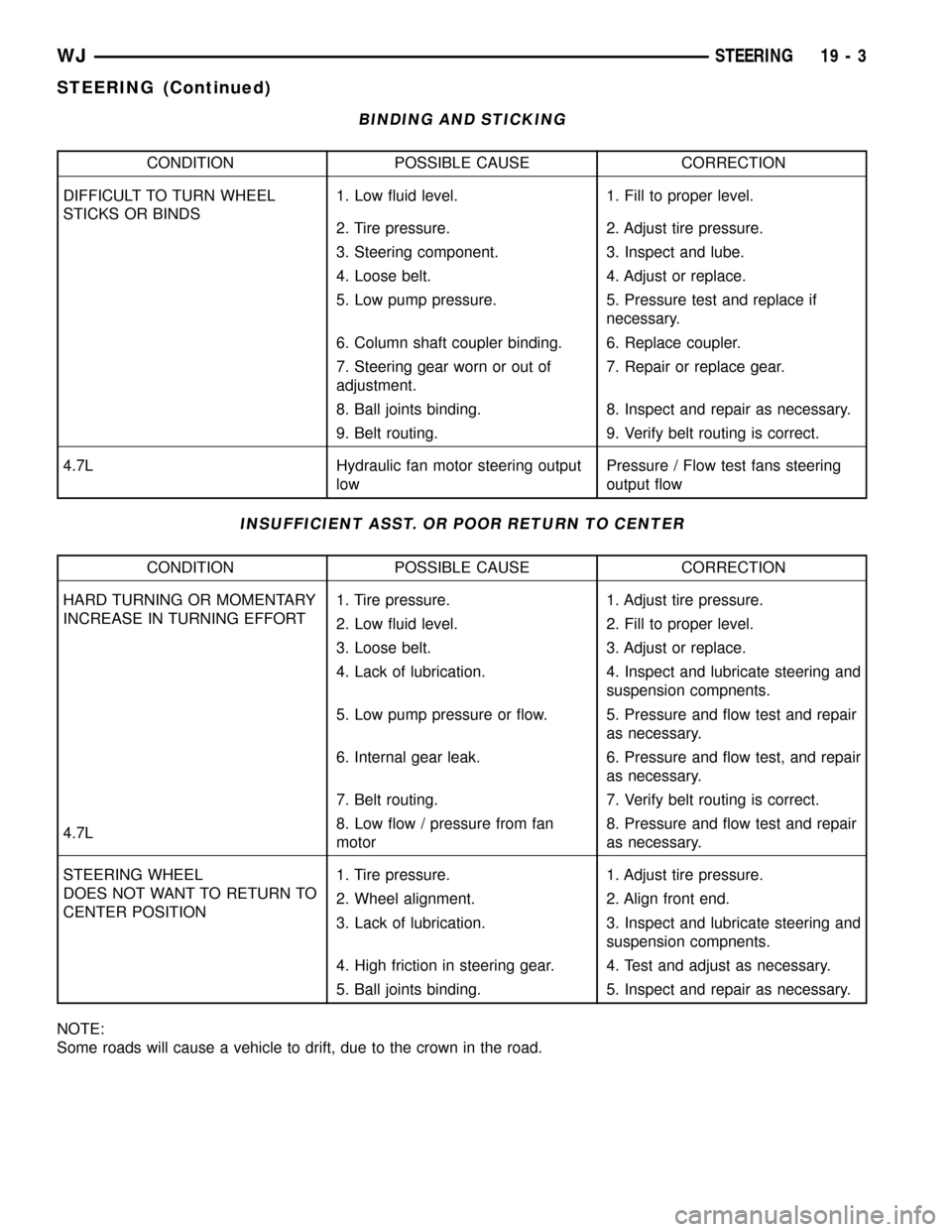
BINDING AND STICKING
CONDITION POSSIBLE CAUSE CORRECTION
DIFFICULT TO TURN WHEEL
STICKS OR BINDS1. Low fluid level. 1. Fill to proper level.
2. Tire pressure. 2. Adjust tire pressure.
3. Steering component. 3. Inspect and lube.
4. Loose belt. 4. Adjust or replace.
5. Low pump pressure. 5. Pressure test and replace if
necessary.
6. Column shaft coupler binding. 6. Replace coupler.
7. Steering gear worn or out of
adjustment.7. Repair or replace gear.
8. Ball joints binding. 8. Inspect and repair as necessary.
9. Belt routing. 9. Verify belt routing is correct.
4.7L Hydraulic fan motor steering output
lowPressure / Flow test fans steering
output flow
INSUFFICIENT ASST. OR POOR RETURN TO CENTER
CONDITION POSSIBLE CAUSE CORRECTION
HARD TURNING OR MOMENTARY
INCREASE IN TURNING EFFORT1. Tire pressure. 1. Adjust tire pressure.
2. Low fluid level. 2. Fill to proper level.
3. Loose belt. 3. Adjust or replace.
4. Lack of lubrication. 4. Inspect and lubricate steering and
suspension compnents.
5. Low pump pressure or flow. 5. Pressure and flow test and repair
as necessary.
6. Internal gear leak. 6. Pressure and flow test, and repair
as necessary.
7. Belt routing. 7. Verify belt routing is correct.
4.7L8. Low flow / pressure from fan
motor8. Pressure and flow test and repair
as necessary.
STEERING WHEEL
DOES NOT WANT TO RETURN TO
CENTER POSITION1. Tire pressure. 1. Adjust tire pressure.
2. Wheel alignment. 2. Align front end.
3. Lack of lubrication. 3. Inspect and lubricate steering and
suspension compnents.
4. High friction in steering gear. 4. Test and adjust as necessary.
5. Ball joints binding. 5. Inspect and repair as necessary.
NOTE:
Some roads will cause a vehicle to drift, due to the crown in the road.
WJSTEERING 19 - 3
STEERING (Continued)
Page 1481 of 2199
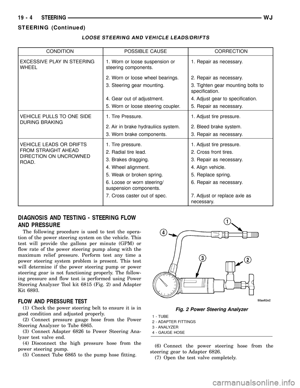
LOOSE STEERING AND VEHICLE LEADS/DRIFTS
CONDITION POSSIBLE CAUSE CORRECTION
EXCESSIVE PLAY IN STEERING
WHEEL1. Worn or loose suspension or
steering components.1. Repair as necessary.
2. Worn or loose wheel bearings. 2. Repair as necessary.
3. Steering gear mounting. 3. Tighten gear mounting bolts to
specification.
4. Gear out of adjustment. 4. Adjust gear to specification.
5. Worn or loose steering coupler. 5. Repair as necessary.
VEHICLE PULLS TO ONE SIDE
DURING BRAKING1. Tire Pressure. 1. Adjust tire pressure.
2. Air in brake hydrauliics system. 2. Bleed brake system.
3. Worn brake components. 3. Repair as necessary.
VEHICLE LEADS OR DRIFTS
FROM STRAIGHT AHEAD
DIRECTION ON UNCROWNED
ROAD.1. Tire pressure. 1. Adjust tire pressure.
2. Radial tire lead. 2. Cross front tires.
3. Brakes dragging. 3. Repair as necessary.
4. Wheel alignment. 4. Align vehicle.
5. Weak or broken spring. 5. Replace spring.
6. Loose or worn steering/
suspension components.6. Repair as necessary.
7. Cross caster out of spec. 7. Adjust or replace axle as
necessary.
DIAGNOSIS AND TESTING - STEERING FLOW
AND PRESSURE
The following procedure is used to test the opera-
tion of the power steering system on the vehicle. This
test will provide the gallons per minute (GPM) or
flow rate of the power steering pump along with the
maximum relief pressure. Perform test any time a
power steering system problem is present. This test
will determine if the power steering pump or power
steering gear is not functioning properly. The follow-
ing pressure and flow test is performed using Power
Steering Analyzer Tool kit 6815 (Fig. 2) and Adapter
Kit 6893.
FLOW AND PRESSURE TEST
(1) Check the power steering belt to ensure it is in
good condition and adjusted properly.
(2) Connect pressure gauge hose from the Power
Steering Analyzer to Tube 6865.
(3) Connect Adapter 6826 to Power Steering Ana-
lyzer test valve end.
(4) Disconnect the high pressure hose from the
power steering pump.
(5) Connect Tube 6865 to the pump hose fitting.(6) Connect the power steering hose from the
steering gear to Adapter 6826.
(7) Open the test valve completely.Fig. 2 Power Steering Analyzer
1 - TUBE
2 - ADAPTER FITTINGS
3 - ANALYZER
4 - GAUGE HOSE
19 - 4 STEERINGWJ
STEERING (Continued)
Page 2026 of 2199
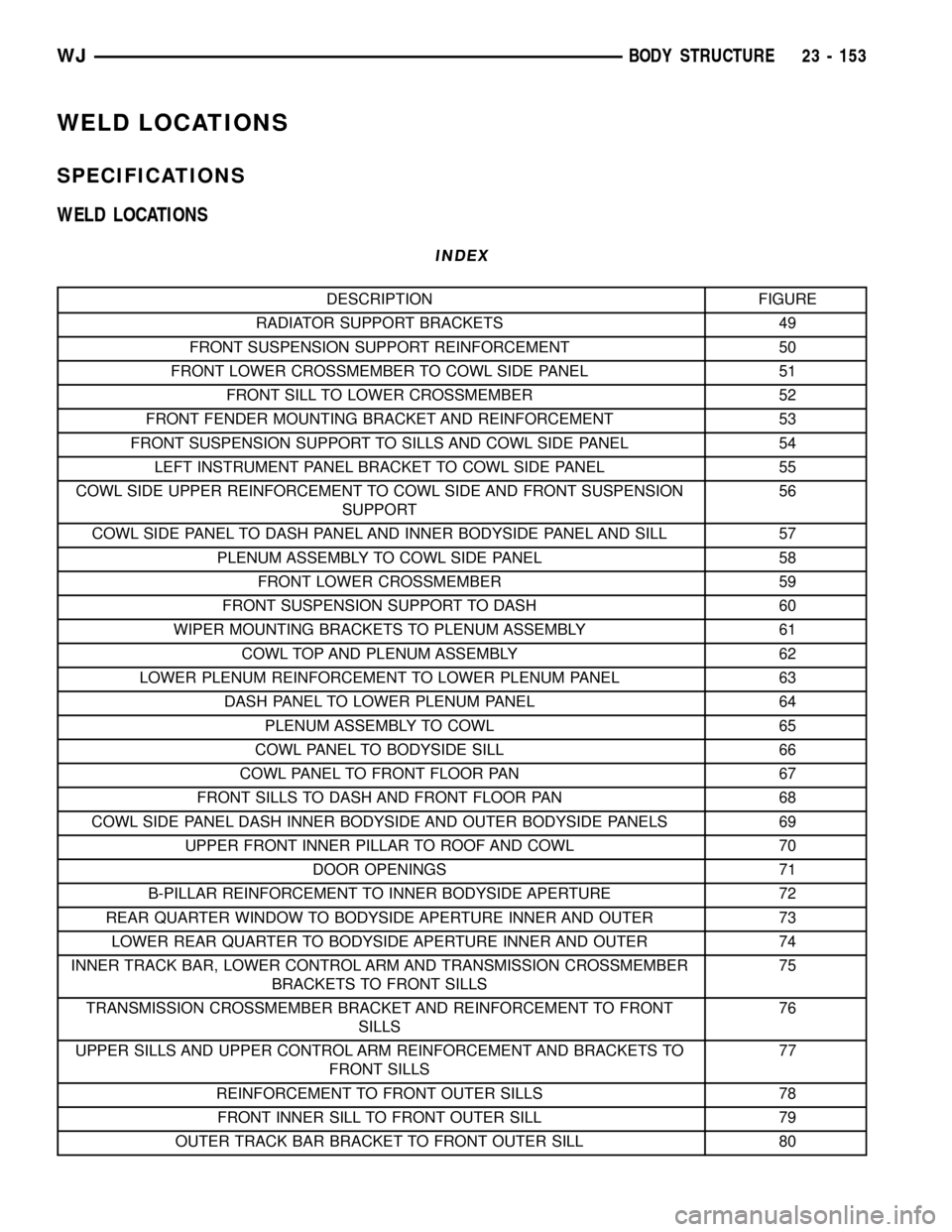
WELD LOCATIONS
SPECIFICATIONS
WELD LOCATIONS
INDEX
DESCRIPTION FIGURE
RADIATOR SUPPORT BRACKETS 49
FRONT SUSPENSION SUPPORT REINFORCEMENT 50
FRONT LOWER CROSSMEMBER TO COWL SIDE PANEL 51
FRONT SILL TO LOWER CROSSMEMBER 52
FRONT FENDER MOUNTING BRACKET AND REINFORCEMENT 53
FRONT SUSPENSION SUPPORT TO SILLS AND COWL SIDE PANEL 54
LEFT INSTRUMENT PANEL BRACKET TO COWL SIDE PANEL 55
COWL SIDE UPPER REINFORCEMENT TO COWL SIDE AND FRONT SUSPENSION
SUPPORT56
COWL SIDE PANEL TO DASH PANEL AND INNER BODYSIDE PANEL AND SILL 57
PLENUM ASSEMBLY TO COWL SIDE PANEL 58
FRONT LOWER CROSSMEMBER 59
FRONT SUSPENSION SUPPORT TO DASH 60
WIPER MOUNTING BRACKETS TO PLENUM ASSEMBLY 61
COWL TOP AND PLENUM ASSEMBLY 62
LOWER PLENUM REINFORCEMENT TO LOWER PLENUM PANEL 63
DASH PANEL TO LOWER PLENUM PANEL 64
PLENUM ASSEMBLY TO COWL 65
COWL PANEL TO BODYSIDE SILL 66
COWL PANEL TO FRONT FLOOR PAN 67
FRONT SILLS TO DASH AND FRONT FLOOR PAN 68
COWL SIDE PANEL DASH INNER BODYSIDE AND OUTER BODYSIDE PANELS 69
UPPER FRONT INNER PILLAR TO ROOF AND COWL 70
DOOR OPENINGS 71
B-PILLAR REINFORCEMENT TO INNER BODYSIDE APERTURE 72
REAR QUARTER WINDOW TO BODYSIDE APERTURE INNER AND OUTER 73
LOWER REAR QUARTER TO BODYSIDE APERTURE INNER AND OUTER 74
INNER TRACK BAR, LOWER CONTROL ARM AND TRANSMISSION CROSSMEMBER
BRACKETS TO FRONT SILLS75
TRANSMISSION CROSSMEMBER BRACKET AND REINFORCEMENT TO FRONT
SILLS76
UPPER SILLS AND UPPER CONTROL ARM REINFORCEMENT AND BRACKETS TO
FRONT SILLS77
REINFORCEMENT TO FRONT OUTER SILLS 78
FRONT INNER SILL TO FRONT OUTER SILL 79
OUTER TRACK BAR BRACKET TO FRONT OUTER SILL 80
WJBODY STRUCTURE 23 - 153
Page 2028 of 2199
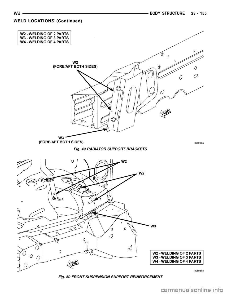
Fig. 49 RADIATOR SUPPORT BRACKETS
Fig. 50 FRONT SUSPENSION SUPPORT REINFORCEMENT
WJBODY STRUCTURE 23 - 155
WELD LOCATIONS (Continued)
Page 2032 of 2199
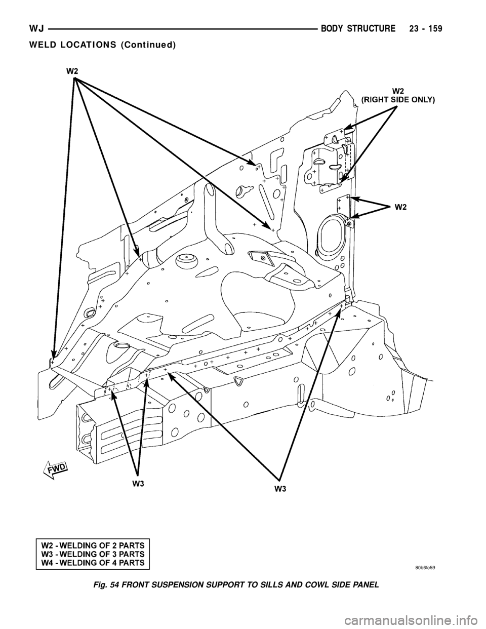
Fig. 54 FRONT SUSPENSION SUPPORT TO SILLS AND COWL SIDE PANEL
WJBODY STRUCTURE 23 - 159
WELD LOCATIONS (Continued)