2002 JEEP GRAND CHEROKEE drain bolt
[x] Cancel search: drain boltPage 1263 of 2199
(2) Drain the coolant (Refer to 7 - COOLING -
STANDARD PROCEDURE) and disconnect the hoses
at the engine thermostat housing and the water
pump inlet. DO NOT waste reusable coolant. If the
solution is clean and is being drained only to service
the engine or cooling system, drain the coolant into a
clean container for reuse.
(3) Remove the air cleaner assembly (Refer to 9 -
ENGINE/AIR INTAKE SYSTEM/AIR CLEANER
HOUSING - REMOVAL).
(4) Remove the cylinder head cover (Refer to 9 -
ENGINE/CYLINDER HEAD/CYLINDER HEAD
COVER(S) - REMOVAL).
(5) Remove the capscrews, bridge and pivot assem-
blies and rocker arms (Refer to 9 - ENGINE/CYLIN-
DER HEAD/ROCKER ARM / ADJUSTER ASSY -
REMOVAL).
(6) Remove the push rods.Retain the push rods,
bridges, pivots and rocker arms in the same
order as removed.
(7) Remove the accessory drive belt (Refer to 7 -
COOLING/ACCESSORY DRIVE/DRIVE BELTS -
REMOVAL).
(8) Remove the A/C compressor mounting bolts
and secure the compressor to the side.
(9) Remove the power steering pump and bracket
from the intake manifold and water pump. Set the
pump and bracket aside. DO NOT disconnect the
hoses.
(10) Perform the Fuel System Pressure Release
procedure. (Refer to 14 - FUEL SYSTEM/FUEL
DELIVERY - STANDARD PROCEDURE).
(11) Disconnect the fuel supply line at the fuel rail.(12) Remove the intake and exhaust manifolds
from the engine cylinder head (Refer to 9 - ENGINE/
MANIFOLDS/INTAKE MANIFOLD - REMOVAL).
(13) Remove the coil rail (Refer to 8 - ELECTRI-
CAL/IGNITION CONTROL/COIL RAIL - REMOV-
AL).
(14) Remove spark plugs (Refer to 8 - ELECTRI-
CAL/IGNITION CONTROL/SPARK PLUG - REMOV-
AL).
(15) Disconnect the temperature sending unit wire
connector.
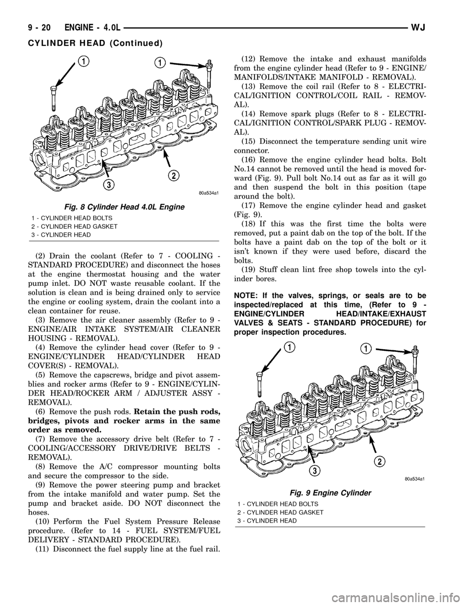
(16) Remove the engine cylinder head bolts. Bolt
No.14 cannot be removed until the head is moved for-
ward (Fig. 9). Pull bolt No.14 out as far as it will go
and then suspend the bolt in this position (tape
around the bolt).
(17) Remove the engine cylinder head and gasket
(Fig. 9).
(18) If this was the first time the bolts were
removed, put a paint dab on the top of the bolt. If the
bolts have a paint dab on the top of the bolt or it
isn't known if they were used before, discard the
bolts.
(19) Stuff clean lint free shop towels into the cyl-
inder bores.
NOTE: If the valves, springs, or seals are to be
inspected/replaced at this time, (Refer to 9 -
ENGINE/CYLINDER HEAD/INTAKE/EXHAUST
VALVES & SEATS - STANDARD PROCEDURE) for
proper inspection procedures.
Fig. 8 Cylinder Head 4.0L Engine
1 - CYLINDER HEAD BOLTS
2 - CYLINDER HEAD GASKET
3 - CYLINDER HEAD
Fig. 9 Engine Cylinder
1 - CYLINDER HEAD BOLTS
2 - CYLINDER HEAD GASKET
3 - CYLINDER HEAD
9 - 20 ENGINE - 4.0LWJ
CYLINDER HEAD (Continued)
Page 1276 of 2199
(16) Install the serpentine drive belt (Refer to 7 -
COOLING/ACCESSORY DRIVE/DRIVE BELTS -
INSTALLATION).
NOTE: During installation, lubricate the hydraulic
valve tappets and all valve components with
MoparTEngine Oil Supplement, or equivalent. TheMoparTEngine Oil Supplement, or equivalent must
remain with the engine oil for at least 1609 km
(1,000 miles). The oil supplement need not be
drained until the next scheduled oil change.
(17) Install the radiator (Refer to 7 - COOLING/
ENGINE/RADIATOR - INSTALLATION).
(18) Check the ignition timing and adjust as nec-
essary.
(19) Install the grille and bumper, if removed.
(20) Connect negative cable to battery.
CONNECTING ROD BEARINGS
STANDARD PROCEDURE - FITTING
CONNECTING ROD BEARINGS
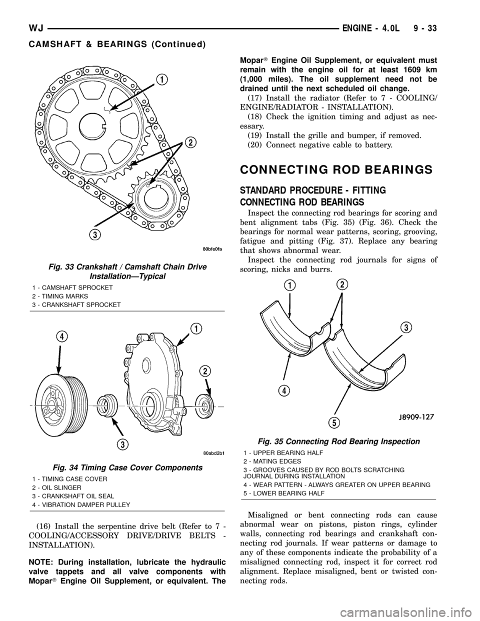
Inspect the connecting rod bearings for scoring and
bent alignment tabs (Fig. 35) (Fig. 36). Check the
bearings for normal wear patterns, scoring, grooving,
fatigue and pitting (Fig. 37). Replace any bearing
that shows abnormal wear.
Inspect the connecting rod journals for signs of
scoring, nicks and burrs.
Misaligned or bent connecting rods can cause
abnormal wear on pistons, piston rings, cylinder
walls, connecting rod bearings and crankshaft con-
necting rod journals. If wear patterns or damage to
any of these components indicate the probability of a
misaligned connecting rod, inspect it for correct rod
alignment. Replace misaligned, bent or twisted con-
necting rods.
Fig. 33 Crankshaft / Camshaft Chain Drive
InstallationÐTypical
1 - CAMSHAFT SPROCKET
2 - TIMING MARKS
3 - CRANKSHAFT SPROCKET
Fig. 34 Timing Case Cover Components
1 - TIMING CASE COVER
2 - OIL SLINGER
3 - CRANKSHAFT OIL SEAL
4 - VIBRATION DAMPER PULLEY
Fig. 35 Connecting Rod Bearing Inspection
1 - UPPER BEARING HALF
2 - MATING EDGES
3 - GROOVES CAUSED BY ROD BOLTS SCRATCHING
JOURNAL DURING INSTALLATION
4 - WEAR PATTERN - ALWAYS GREATER ON UPPER BEARING
5 - LOWER BEARING HALF
WJENGINE - 4.0L 9 - 33
CAMSHAFT & BEARINGS (Continued)
Page 1284 of 2199
(e) If end play is not within specification, inspect
crankshaft thrust faces for wear. If no wear is
apparent, replace the thrust bearing and measure
end play. If end play is still not within specifica-
tion, replace the crankshaft.
(11) If the crankshaft was removed, install the
crankshaft into the cylinder block.
(12) Install main bearing cap brace tighten nuts to
47 N´m (35 ft. lbs.) torque.
(13) Install oil pump assy. and tighten attaching
bolts to 23 N´m (17 ft. lbs.)
(14) Install the oil pan (Refer to 9 - ENGINE/LU-
BRICATION/OIL PAN - INSTALLATION).
(15) Install the drain plug. Tighten the plug to 34
N´m (25 ft. lbs.) torque.
(16) Lower the vehicle.
(17) Install the spark plugs. Tighten the plugs to
37 N´m (27 ft. lbs.) torque.
(18) Fill the oil pan with engine oil to the full
mark on the dipstick level.
(19) Connect negative cable to battery.
CRANKSHAFT OIL SEAL -
FRONT
REMOVAL
This procedure is done with the timing case cover
installed.
(1) Disconnect negative cable from battery.
(2) Remove the serpentine drive belt (Refer to 7 -
COOLING/ACCESSORY DRIVE/DRIVE BELTS -
REMOVAL).(3) Remove the vibration damper (Refer to 9 -
ENGINE/ENGINE BLOCK/VIBRATION DAMPER -
REMOVAL).
(4) Remove the radiator shroud.
(5) Carefully remove the oil seal. Make sure seal
bore is clean.
INSTALLATION
This procedure is done with the timing case cover
installed.
(1) Position the replacement oil seal on Timing
Case Cover Alignment and Seal Installation Tool
6139 with seal open end facing inward. Apply a light
film of Perfect Seal, or equivalent, on the outside
diameter of the seal. Lightly coat the crankshaft with
engine oil.
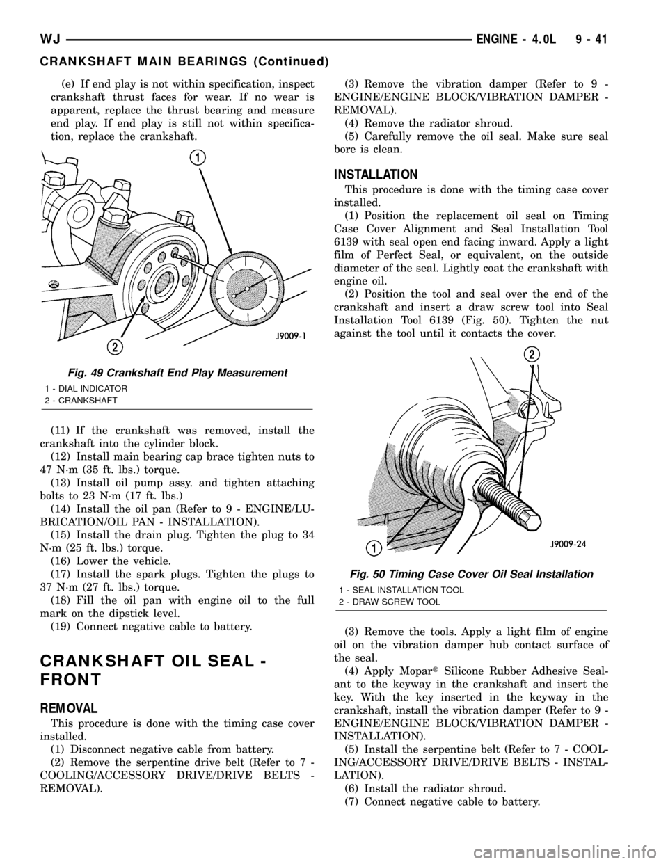
(2) Position the tool and seal over the end of the
crankshaft and insert a draw screw tool into Seal
Installation Tool 6139 (Fig. 50). Tighten the nut
against the tool until it contacts the cover.
(3) Remove the tools. Apply a light film of engine
oil on the vibration damper hub contact surface of
the seal.
(4) Apply MopartSilicone Rubber Adhesive Seal-
ant to the keyway in the crankshaft and insert the
key. With the key inserted in the keyway in the
crankshaft, install the vibration damper (Refer to 9 -
ENGINE/ENGINE BLOCK/VIBRATION DAMPER -
INSTALLATION).
(5) Install the serpentine belt (Refer to 7 - COOL-
ING/ACCESSORY DRIVE/DRIVE BELTS - INSTAL-
LATION).
(6) Install the radiator shroud.
(7) Connect negative cable to battery.
Fig. 49 Crankshaft End Play Measurement
1 - DIAL INDICATOR
2 - CRANKSHAFT
Fig. 50 Timing Case Cover Oil Seal Installation
1 - SEAL INSTALLATION TOOL
2 - DRAW SCREW TOOL
WJENGINE - 4.0L 9 - 41
CRANKSHAFT MAIN BEARINGS (Continued)
Page 1298 of 2199
(10) Place a piece of wood (2 x 2) between the jack
stand and the engine vibration damper.
(11) Remove the engine mount through bolts.
(12) Using the jack stand, raise the engine until
adequate clearance is obtained to remove the oil pan.
(13) Remove transmission oil cooling lines (if
equipped) and oxygen sensor wiring supports that
are attached to the oil pan studs.
(14) Remove the oil pan bolts and studs. Carefully
slide the oil pan and gasket to the rear. If equipped
with an oil level sensor, take care not to damage the
sensor.
INSTALLATION
(1) Clean the block and pan gasket surfaces.
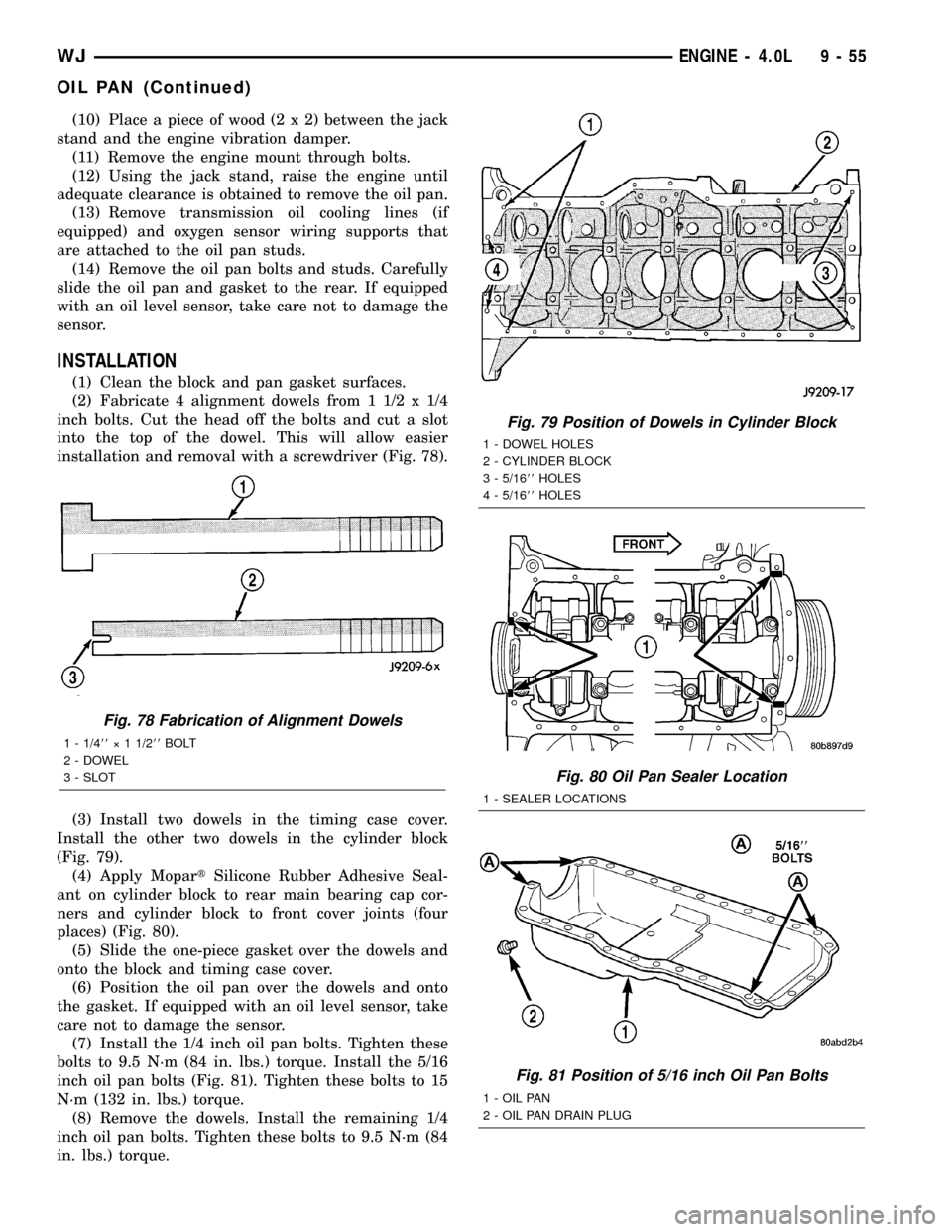
(2) Fabricate 4 alignment dowels from 1 1/2 x 1/4
inch bolts. Cut the head off the bolts and cut a slot
into the top of the dowel. This will allow easier
installation and removal with a screwdriver (Fig. 78).
(3) Install two dowels in the timing case cover.
Install the other two dowels in the cylinder block
(Fig. 79).
(4) Apply MopartSilicone Rubber Adhesive Seal-
ant on cylinder block to rear main bearing cap cor-
ners and cylinder block to front cover joints (four
places) (Fig. 80).
(5) Slide the one-piece gasket over the dowels and
onto the block and timing case cover.
(6) Position the oil pan over the dowels and onto
the gasket. If equipped with an oil level sensor, take
care not to damage the sensor.
(7) Install the 1/4 inch oil pan bolts. Tighten these
bolts to 9.5 N´m (84 in. lbs.) torque. Install the 5/16
inch oil pan bolts (Fig. 81). Tighten these bolts to 15
N´m (132 in. lbs.) torque.
(8) Remove the dowels. Install the remaining 1/4
inch oil pan bolts. Tighten these bolts to 9.5 N´m (84
in. lbs.) torque.
Fig. 78 Fabrication of Alignment Dowels
1 - 1/488ý 1 1/288BOLT
2 - DOWEL
3 - SLOT
Fig. 79 Position of Dowels in Cylinder Block
1 - DOWEL HOLES
2 - CYLINDER BLOCK
3 - 5/1688HOLES
4 - 5/1688HOLES
Fig. 80 Oil Pan Sealer Location
1 - SEALER LOCATIONS
Fig. 81 Position of 5/16 inch Oil Pan Bolts
1 - OIL PAN
2 - OIL PAN DRAIN PLUG
WJENGINE - 4.0L 9 - 55
OIL PAN (Continued)
Page 1299 of 2199
(9) Lower the engine until it is properly located on
the engine mounts.
(10) Install the through bolts and tighten the nuts.
(11) Lower the jack stand and remove the piece of
wood.
(12) Install the engine flywheel and transmission
torque converter housing access cover.
(13) Install the engine starter motor. (Refer to 8 -
ELECTRICAL/STARTING/STARTER MOTOR -
INSTALLATION).
(14) Connect the exhaust pipe to the hanger and to
the engine exhaust manifold.
(15) Install transmission oil cooling lines (if
equipped) and oxygen sensor wiring supports that
attach to the oil pan studs.
(16) Install the oil pan drain plug (Fig. 81).
Tighten the plug to 34 N´m (25 ft. lbs.) torque.
(17) Lower the vehicle.
(18) Connect negative cable to battery.
(19) Fill the oil pan with engine oil to the specified
level.
WARNING: USE EXTREME CAUTION WHEN THE
ENGINE IS OPERATING. DO NOT STAND IN A
DIRECT LINE WITH THE FAN. DO NOT PUT YOUR
HANDS NEAR THE PULLEYS, BELTS OR FAN. DO
NOT WEAR LOOSE CLOTHING.
(20) Start the engine and inspect for leaks.
ENGINE OIL PRESSURE
SENSOR
DESCRIPTION
The 3±wire, solid-state engine oil pressure sensor
(sending unit) is located in an engine oil pressure
gallery.
OPERATION
The oil pressure sensor uses three circuits. They
are:
²A 5±volt power supply from the Powertrain Con-
trol Module (PCM)
²A sensor ground through the PCM's sensor
return
²A signal to the PCM relating to engine oil pres-
sure
The oil pressure sensor has a 3±wire electrical
function very much like the Manifold Absolute Pres-
sure (MAP) sensor. Meaning different pressures
relate to different output voltages.
A 5±volt supply is sent to the sensor from the PCM
to power up the sensor. The sensor returns a voltage
signal back to the PCM relating to engine oil pres-
sure. This signal is then transferred (bussed) to theinstrument panel on either a CCD or PCI bus circuit
(depending on vehicle line) to operate the oil pressure
gauge and the check gauges lamp. Ground for the
sensor is provided by the PCM through a low-noise
sensor return.
OIL PUMP
REMOVAL
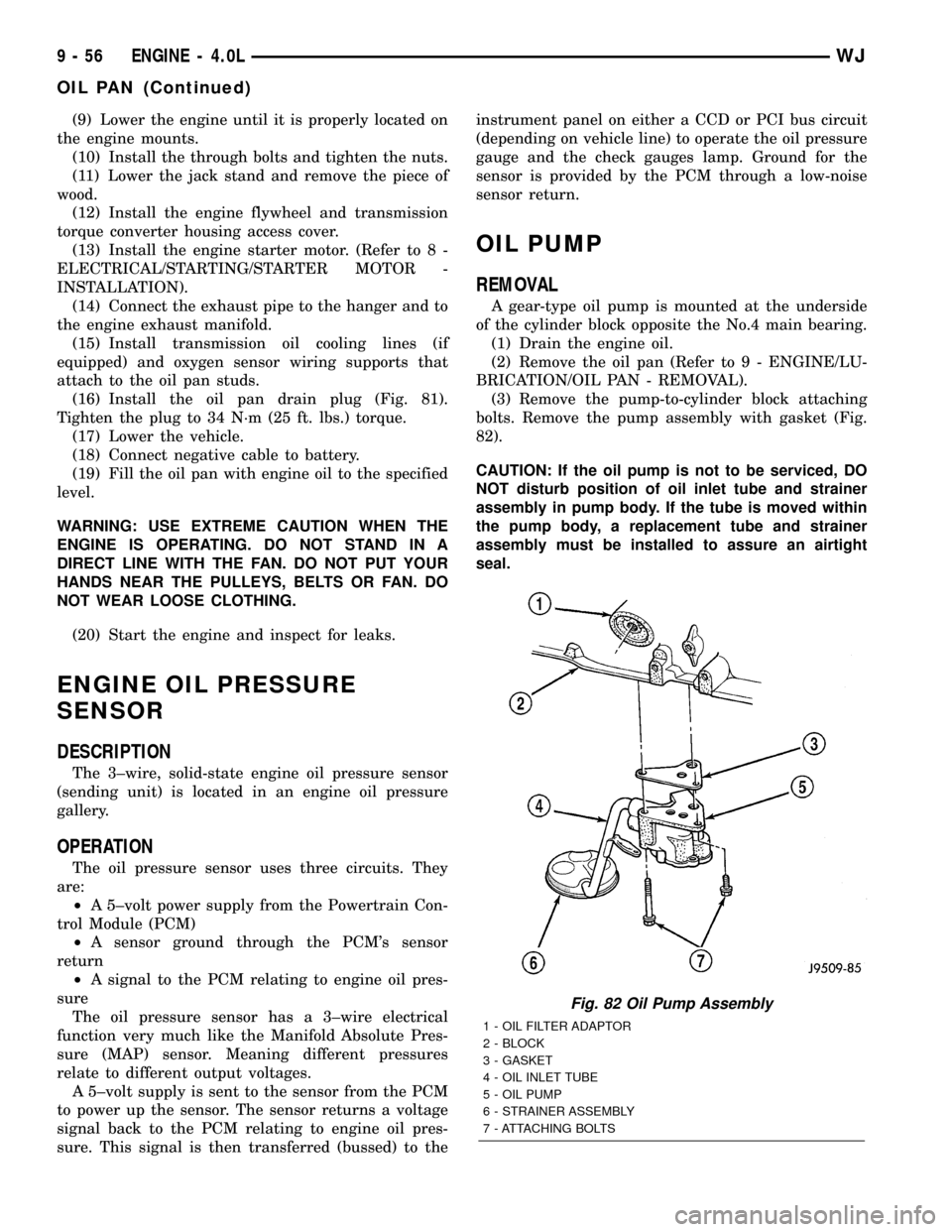
A gear-type oil pump is mounted at the underside
of the cylinder block opposite the No.4 main bearing.
(1) Drain the engine oil.
(2) Remove the oil pan (Refer to 9 - ENGINE/LU-
BRICATION/OIL PAN - REMOVAL).
(3) Remove the pump-to-cylinder block attaching
bolts. Remove the pump assembly with gasket (Fig.
82).
CAUTION: If the oil pump is not to be serviced, DO
NOT disturb position of oil inlet tube and strainer
assembly in pump body. If the tube is moved within
the pump body, a replacement tube and strainer
assembly must be installed to assure an airtight
seal.
Fig. 82 Oil Pump Assembly
1 - OIL FILTER ADAPTOR
2 - BLOCK
3 - GASKET
4 - OIL INLET TUBE
5 - OIL PUMP
6 - STRAINER ASSEMBLY
7 - ATTACHING BOLTS
9 - 56 ENGINE - 4.0LWJ
OIL PAN (Continued)
Page 1314 of 2199
²Abrasive pad or paper to clean cylinder block
and head
²High speed power tool with an abrasive pad or a
wire brush (Fig. 2)
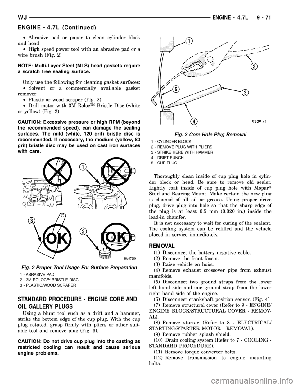
NOTE: Multi-Layer Steel (MLS) head gaskets require
a scratch free sealing surface.
Only use the following for cleaning gasket surfaces:
²Solvent or a commercially available gasket
remover
²Plastic or wood scraper (Fig. 2)
²Drill motor with 3M RolocŸ Bristle Disc (white
or yellow) (Fig. 2)
CAUTION: Excessive pressure or high RPM (beyond
the recommended speed), can damage the sealing
surfaces. The mild (white, 120 grit) bristle disc is
recommended. If necessary, the medium (yellow, 80
grit) bristle disc may be used on cast iron surfaces
with care.
STANDARD PROCEDURE - ENGINE CORE AND
OIL GALLERY PLUGS
Using a blunt tool such as a drift and a hammer,
strike the bottom edge of the cup plug. With the cup
plug rotated, grasp firmly with pliers or other suit-
able tool and remove plug (Fig. 3).
CAUTION: Do not drive cup plug into the casting as
restricted cooling can result and cause serious
engine problems.Thoroughly clean inside of cup plug hole in cylin-
der block or head. Be sure to remove old sealer.
Lightly coat inside of cup plug hole with Mopart
Stud and Bearing Mount. Make certain the new plug
is cleaned of all oil or grease. Using proper drive
plug, drive plug into hole so that the sharp edge of
the plug is at least 0.5 mm (0.020 in.) inside the
lead-in chamfer.
It is not necessary to wait for curing of the sealant.
The cooling system can be refilled and the vehicle
placed in service immediately.
REMOVAL
(1) Disconnect the battery negative cable.
(2) Remove the front fascia.
(3) Raise vehicle on hoist.
(4) Remove exhaust crossover pipe from exhaust
manifolds.
(5) Disconnect two ground straps from the lower
left hand side and one ground strap from the lower
right hand side of the engine.
(6) Disconnect crankshaft position sensor. (Fig. 4)
(7) Remove structural cover (Refer to 9 - ENGINE/
ENGINE BLOCK/STRUCTURAL COVER - REMOV-
AL).
(8) Remove starter. (Refer to 8 - ELECTRICAL/
STARTING/STARTER MOTOR - REMOVAL).
(9) Remove rubber splash shield.
(10) Drain cooling system (Refer to 7 - COOLING -
STANDARD PROCEDURE).
(11) Remove torque converter bolts.
(12) Remove transmission to engine mounting
bolts.
Fig. 2 Proper Tool Usage For Surface Preparation
1 - ABRASIVE PAD
2 - 3M ROLOCŸ BRISTLE DISC
3 - PLASTIC/WOOD SCRAPER
Fig. 3 Core Hole Plug Removal
1 - CYLINDER BLOCK
2 - REMOVE PLUG WITH PLIERS
3 - STRIKE HERE WITH HAMMER
4 - DRIFT PUNCH
5 - CUP PLUG
WJENGINE - 4.7L 9 - 71
ENGINE - 4.7L (Continued)
Page 1323 of 2199
DESCRIPTION N´m Ft. In.
Lbs. Lbs.
Exhaust Manifold Heat
ShieldÐNuts8Ð72
Then loosen 45É
FlexplateÐBolts 60 45 Ð
Engine Mount Bracket to
BlockÐBolts61 45 Ð
Rear Mount to
TransmissionÐBolts46 34 Ð
Generator MountingÐBolts
M10 Bolts 54 40 Ð
M8 Bolts 28 Ð 250
Intake ManifoldÐBolts 12 Ð 105
Refer to Procedure
for
Tightening Sequence
Oil PanÐBolts 15 Ð 130
Oil PanÐDrain Plug 34 25 Ð
Oil PumpÐBolts 28 Ð 250
Oil Pump CoverÐBolts 12 Ð 105
Oil Pickup TubeÐBolt and
Nut28 Ð 250
Oil Dipstick Tube to Engine
BlockÐBolt 15 Ð 130
Oil Fill TubeÐBolts 12 Ð 105
Timing Chain GuideÐBolts 28 Ð 250
Timing Chain Tensioner
ArmÐSpecial
Pin Bolt 17 Ð 150
Hydraulic TensionerÐBolts 28 Ð 250
Timing Chain Primary
TensionerÐBolts28 Ð 250
Timing Drive Idler SprocketÐ
Bolt34 25 Ð
Thermostat HousingÐBolts 13 Ð 115
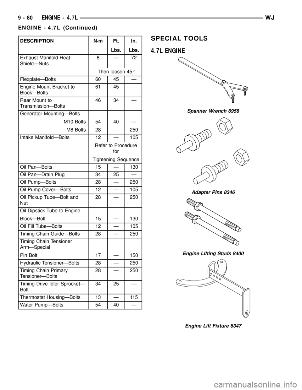
Water PumpÐBolts 54 40 ÐSPECIAL TOOLS
4.7L ENGINE
Spanner Wrench 6958
Adapter Pins 8346
Engine Lifting Studs 8400
Engine Lift Fixture 8347
9 - 80 ENGINE - 4.7LWJ
ENGINE - 4.7L (Continued)
Page 1327 of 2199
AIR CLEANER HOUSING
REMOVAL - 4.7L
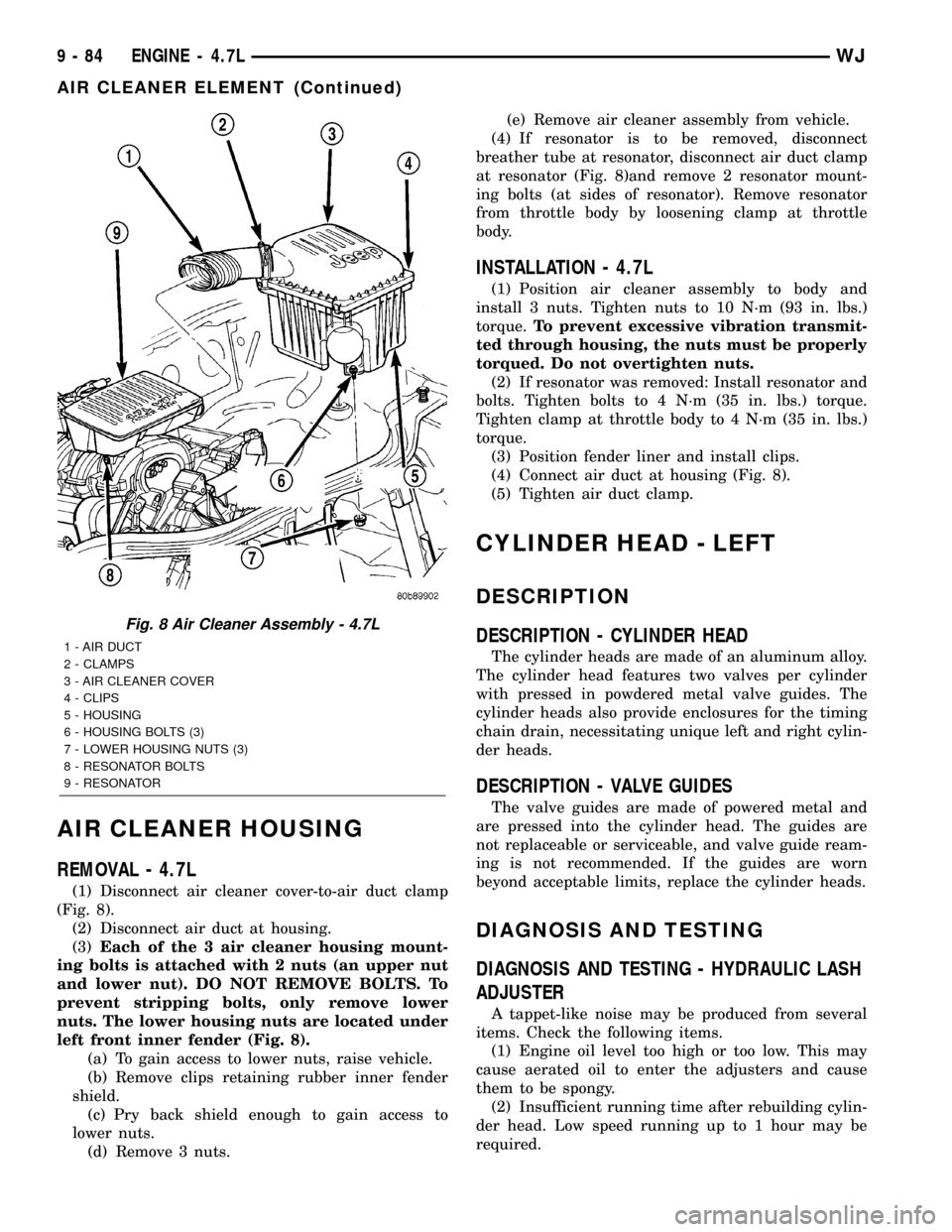
(1) Disconnect air cleaner cover-to-air duct clamp
(Fig. 8).
(2) Disconnect air duct at housing.
(3)Each of the 3 air cleaner housing mount-
ing bolts is attached with 2 nuts (an upper nut
and lower nut). DO NOT REMOVE BOLTS. To
prevent stripping bolts, only remove lower
nuts. The lower housing nuts are located under
left front inner fender (Fig. 8).
(a) To gain access to lower nuts, raise vehicle.
(b) Remove clips retaining rubber inner fender
shield.
(c) Pry back shield enough to gain access to
lower nuts.
(d) Remove 3 nuts.(e) Remove air cleaner assembly from vehicle.
(4) If resonator is to be removed, disconnect
breather tube at resonator, disconnect air duct clamp
at resonator (Fig. 8)and remove 2 resonator mount-
ing bolts (at sides of resonator). Remove resonator
from throttle body by loosening clamp at throttle
body.
INSTALLATION - 4.7L
(1) Position air cleaner assembly to body and
install 3 nuts. Tighten nuts to 10 N´m (93 in. lbs.)
torque.To prevent excessive vibration transmit-
ted through housing, the nuts must be properly
torqued. Do not overtighten nuts.
(2) If resonator was removed: Install resonator and
bolts. Tighten bolts to 4 N´m (35 in. lbs.) torque.
Tighten clamp at throttle body to 4 N´m (35 in. lbs.)
torque.
(3) Position fender liner and install clips.
(4) Connect air duct at housing (Fig. 8).
(5) Tighten air duct clamp.
CYLINDER HEAD - LEFT
DESCRIPTION
DESCRIPTION - CYLINDER HEAD
The cylinder heads are made of an aluminum alloy.
The cylinder head features two valves per cylinder
with pressed in powdered metal valve guides. The
cylinder heads also provide enclosures for the timing
chain drain, necessitating unique left and right cylin-
der heads.
DESCRIPTION - VALVE GUIDES
The valve guides are made of powered metal and
are pressed into the cylinder head. The guides are
not replaceable or serviceable, and valve guide ream-
ing is not recommended. If the guides are worn
beyond acceptable limits, replace the cylinder heads.
DIAGNOSIS AND TESTING
DIAGNOSIS AND TESTING - HYDRAULIC LASH
ADJUSTER
A tappet-like noise may be produced from several
items. Check the following items.
(1) Engine oil level too high or too low. This may
cause aerated oil to enter the adjusters and cause
them to be spongy.
(2) Insufficient running time after rebuilding cylin-
der head. Low speed running up to 1 hour may be
required.
Fig. 8 Air Cleaner Assembly - 4.7L
1 - AIR DUCT
2 - CLAMPS
3 - AIR CLEANER COVER
4 - CLIPS
5 - HOUSING
6 - HOUSING BOLTS (3)
7 - LOWER HOUSING NUTS (3)
8 - RESONATOR BOLTS
9 - RESONATOR
9 - 84 ENGINE - 4.7LWJ
AIR CLEANER ELEMENT (Continued)