2002 JEEP GRAND CHEROKEE Valve cover torque
[x] Cancel search: Valve cover torquePage 1371 of 2199
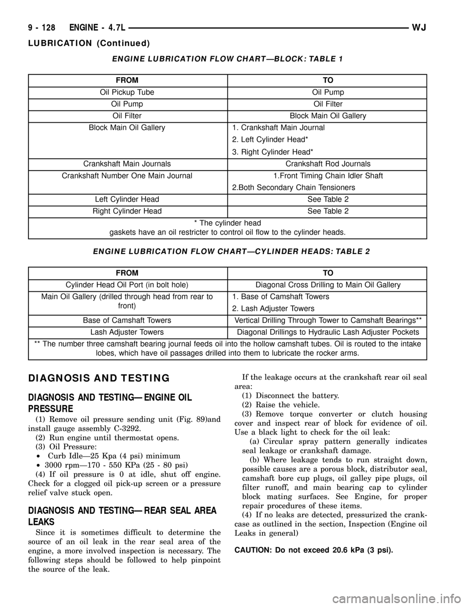
ENGINE LUBRICATION FLOW CHARTÐBLOCK: TABLE 1
FROM TO
Oil Pickup Tube Oil Pump
Oil Pump Oil Filter
Oil Filter Block Main Oil Gallery
Block Main Oil Gallery 1. Crankshaft Main Journal
2. Left Cylinder Head*
3. Right Cylinder Head*
Crankshaft Main Journals Crankshaft Rod Journals
Crankshaft Number One Main Journal 1.Front Timing Chain Idler Shaft
2.Both Secondary Chain Tensioners
Left Cylinder Head See Table 2
Right Cylinder Head See Table 2
* The cylinder head
gaskets have an oil restricter to control oil flow to the cylinder heads.
ENGINE LUBRICATION FLOW CHARTÐCYLINDER HEADS: TABLE 2
FROM TO
Cylinder Head Oil Port (in bolt hole) Diagonal Cross Drilling to Main Oil Gallery
Main Oil Gallery (drilled through head from rear to
front)1. Base of Camshaft Towers
2. Lash Adjuster Towers
Base of Camshaft Towers Vertical Drilling Through Tower to Camshaft Bearings**
Lash Adjuster Towers Diagonal Drillings to Hydraulic Lash Adjuster Pockets
** The number three camshaft bearing journal feeds oil into the hollow camshaft tubes. Oil is routed to the intake
lobes, which have oil passages drilled into them to lubricate the rocker arms.
DIAGNOSIS AND TESTING
DIAGNOSIS AND TESTINGÐENGINE OIL
PRESSURE
(1) Remove oil pressure sending unit (Fig. 89)and
install gauge assembly C-3292.
(2) Run engine until thermostat opens.
(3) Oil Pressure:
²Curb IdleÐ25 Kpa (4 psi) minimum
²3000 rpmÐ170 - 550 KPa (25 - 80 psi)
(4) If oil pressure is 0 at idle, shut off engine.
Check for a clogged oil pick-up screen or a pressure
relief valve stuck open.
DIAGNOSIS AND TESTINGÐREAR SEAL AREA
LEAKS
Since it is sometimes difficult to determine the
source of an oil leak in the rear seal area of the
engine, a more involved inspection is necessary. The
following steps should be followed to help pinpoint
the source of the leak.If the leakage occurs at the crankshaft rear oil seal
area:
(1) Disconnect the battery.
(2) Raise the vehicle.
(3) Remove torque converter or clutch housing
cover and inspect rear of block for evidence of oil.
Use a black light to check for the oil leak:
(a) Circular spray pattern generally indicates
seal leakage or crankshaft damage.
(b) Where leakage tends to run straight down,
possible causes are a porous block, distributor seal,
camshaft bore cup plugs, oil galley pipe plugs, oil
filter runoff, and main bearing cap to cylinder
block mating surfaces. See Engine, for proper
repair procedures of these items.
(4) If no leaks are detected, pressurized the crank-
case as outlined in the section, Inspection (Engine oil
Leaks in general)
CAUTION: Do not exceed 20.6 kPa (3 psi).
9 - 128 ENGINE - 4.7LWJ
LUBRICATION (Continued)
Page 1387 of 2199
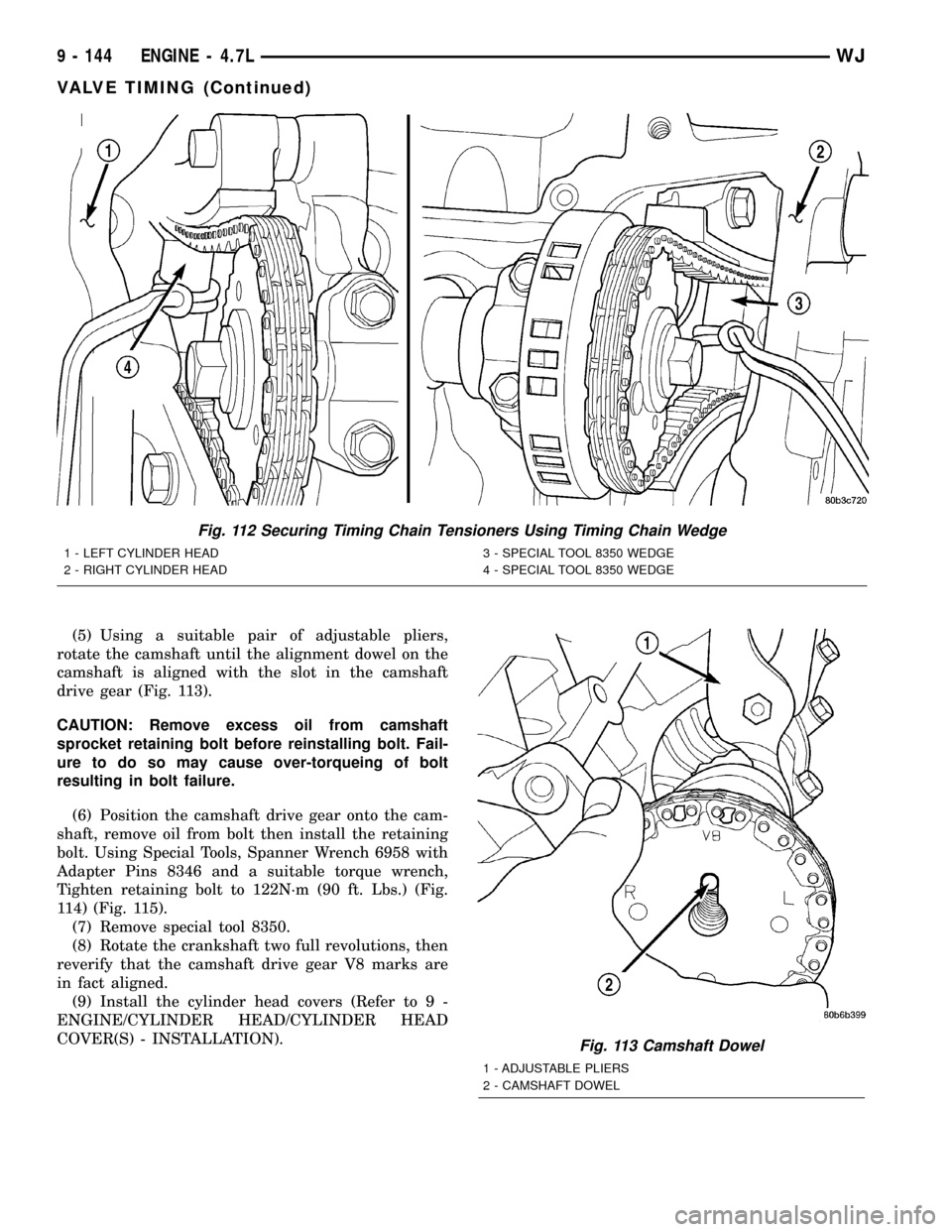
(5) Using a suitable pair of adjustable pliers,
rotate the camshaft until the alignment dowel on the
camshaft is aligned with the slot in the camshaft
drive gear (Fig. 113).
CAUTION: Remove excess oil from camshaft
sprocket retaining bolt before reinstalling bolt. Fail-
ure to do so may cause over-torqueing of bolt
resulting in bolt failure.
(6) Position the camshaft drive gear onto the cam-
shaft, remove oil from bolt then install the retaining
bolt. Using Special Tools, Spanner Wrench 6958 with
Adapter Pins 8346 and a suitable torque wrench,
Tighten retaining bolt to 122N´m (90 ft. Lbs.) (Fig.
114) (Fig. 115).
(7) Remove special tool 8350.
(8) Rotate the crankshaft two full revolutions, then
reverify that the camshaft drive gear V8 marks are
in fact aligned.
(9) Install the cylinder head covers (Refer to 9 -
ENGINE/CYLINDER HEAD/CYLINDER HEAD
COVER(S) - INSTALLATION).
Fig. 112 Securing Timing Chain Tensioners Using Timing Chain Wedge
1 - LEFT CYLINDER HEAD
2 - RIGHT CYLINDER HEAD3 - SPECIAL TOOL 8350 WEDGE
4 - SPECIAL TOOL 8350 WEDGE
Fig. 113 Camshaft Dowel
1 - ADJUSTABLE PLIERS
2 - CAMSHAFT DOWEL
9 - 144 ENGINE - 4.7LWJ
VALVE TIMING (Continued)
Page 1388 of 2199
STANDARD PROCEDUREÐMEASURING
TIMING CHAIN WEAR
NOTE: This procedure must be performed with the
timing chain cover removed.
(1) Remove the timing chain cover. (Refer to 9 -
ENGINE/VALVE TIMING/TIMING BELT / CHAIN
COVER(S) - REMOVAL).
(2) To determine if the secondary timing chains
are worn, rotate the engine clockwise until maximum
tensioner piston extension is obtained. Measure the
distance between the secondary timing chain ten-
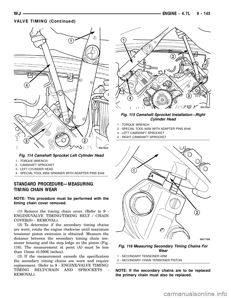
sioner housing and the step ledge on the piston (Fig.
116). The measurement at point (A) must be less
than 15mm (0.5906 inches).
(3) If the measurement exceeds the specification
the secondary timing chains are worn and require
replacement. (Refer to 9 - ENGINE/VALVE TIMING/
TIMING BELT/CHAIN AND SPROCKETS -
REMOVAL).NOTE: If the secondary chains are to be replaced
the primary chain must also be replaced.
Fig. 114 Camshaft Sprocket Left Cylinder Head
1 - TORQUE WRENCH
2 - CAMSHAFT SPROCKET
3 - LEFT CYLINDER HEAD
4 - SPECIAL TOOL 6958 SPANNER WITH ADAPTER PINS 8346
Fig. 115 Camshaft Sprocket InstallationÐRight
Cylinder Head
1 - TORQUE WRENCH
2 - SPECIAL TOOL 6958 WITH ADAPTER PINS 8346
3 - LEFT CAMSHAFT SPROCKET
4 - RIGHT CAMSHAFT SPROCKET
Fig. 116 Measuring Secondary Timing Chains For
Wear
1 - SECONDARY TENSIONER ARM
2 - SECONDARY CHAIN TENSIONER PISTON
WJENGINE - 4.7L 9 - 145
VALVE TIMING (Continued)
Page 1396 of 2199
(22) Install timing chain cover (Refer to 9 -
ENGINE/VALVE TIMING/TIMING BELT / CHAIN
COVER(S) - INSTALLATION) and crankshaft
damper (Refer to 9 - ENGINE/ENGINE BLOCK/VI-
BRATION DAMPER - INSTALLATION).
(23) Install cylinder head covers (Refer to 9 -
ENGINE/CYLINDER HEAD/CYLINDER HEAD
COVER(S) - INSTALLATION).
NOTE: Before installing threaded plug in right cylin-
der head, the plug must be coated with sealant to
prevent leaks.
(24) Coat the large threaded access plug with
MopartThread Sealant with Teflon, then install
into the right cylinder head and tighten to 81 N´m
(60 ft. lbs.) (Fig. 122).
(25) Install the oil fill housing.
(26) Install access plug in left cylinder head (Fig.
122).
(27) Install power steering pump.
(28) Install radiator fan (Refer to 7 - COOLING/
ENGINE/RADIATOR FAN - INSTALLATION).
(29) Fill cooling system (Refer to 7 - COOLING -
STANDARD PROCEDURE).
(30) Connect negative cable to battery.
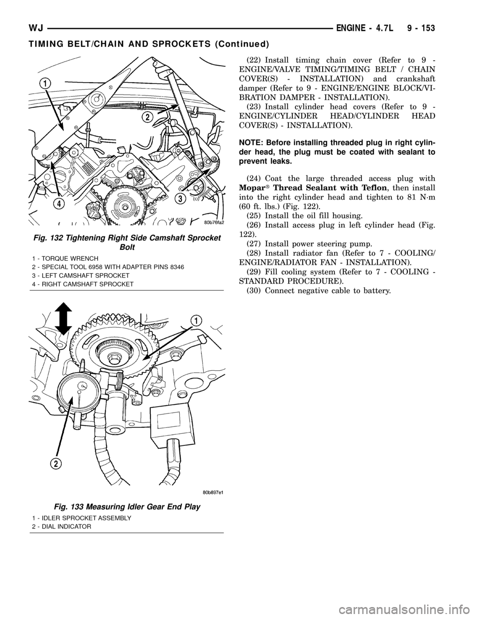
Fig. 132 Tightening Right Side Camshaft Sprocket
Bolt
1 - TORQUE WRENCH
2 - SPECIAL TOOL 6958 WITH ADAPTER PINS 8346
3 - LEFT CAMSHAFT SPROCKET
4 - RIGHT CAMSHAFT SPROCKET
Fig. 133 Measuring Idler Gear End Play
1 - IDLER SPROCKET ASSEMBLY
2 - DIAL INDICATOR
WJENGINE - 4.7L 9 - 153
TIMING BELT/CHAIN AND SPROCKETS (Continued)
Page 1473 of 2199
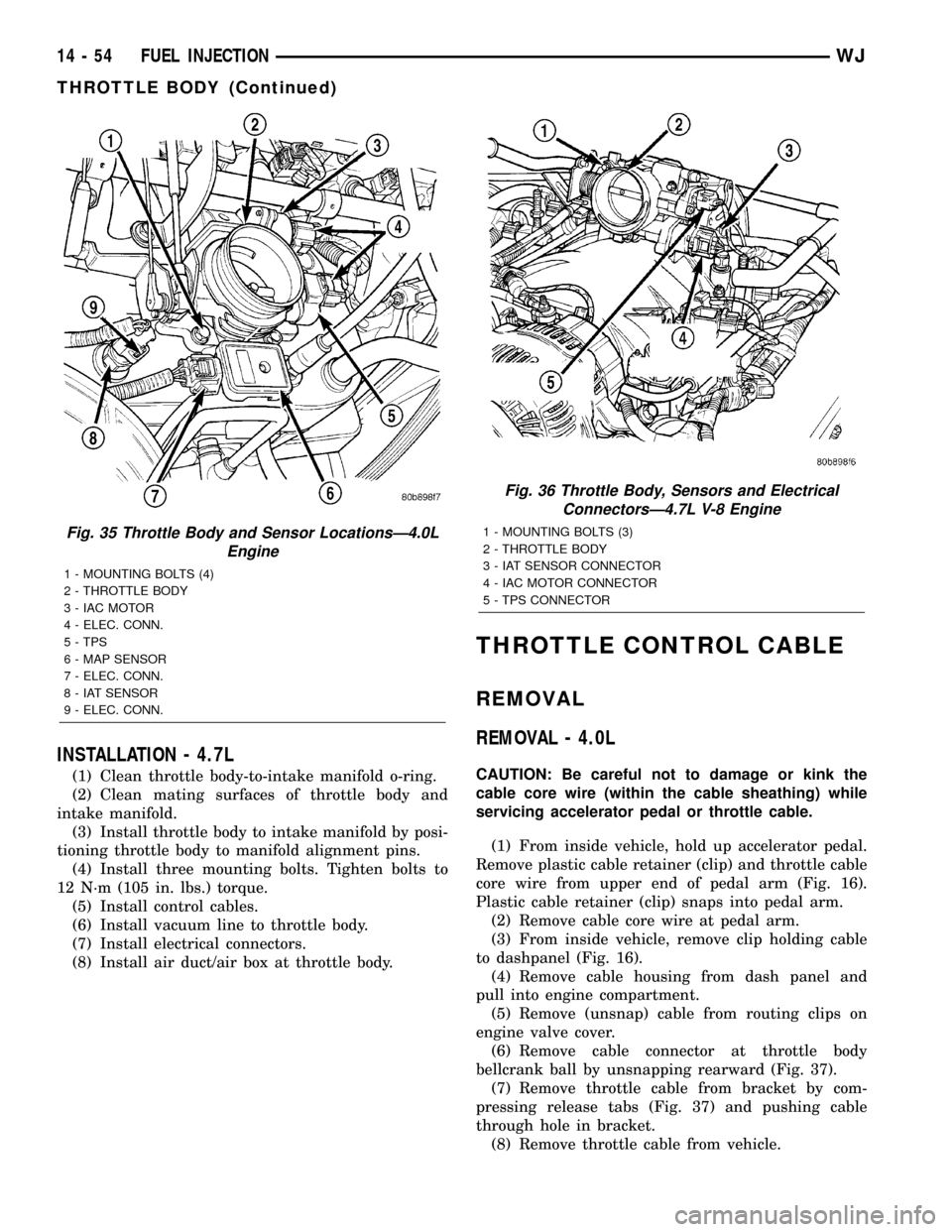
INSTALLATION - 4.7L
(1) Clean throttle body-to-intake manifold o-ring.
(2) Clean mating surfaces of throttle body and
intake manifold.
(3) Install throttle body to intake manifold by posi-
tioning throttle body to manifold alignment pins.
(4) Install three mounting bolts. Tighten bolts to
12 N´m (105 in. lbs.) torque.
(5) Install control cables.
(6) Install vacuum line to throttle body.
(7) Install electrical connectors.
(8) Install air duct/air box at throttle body.
THROTTLE CONTROL CABLE
REMOVAL
REMOVAL - 4.0L
CAUTION: Be careful not to damage or kink the
cable core wire (within the cable sheathing) while
servicing accelerator pedal or throttle cable.
(1) From inside vehicle, hold up accelerator pedal.
Remove plastic cable retainer (clip) and throttle cable
core wire from upper end of pedal arm (Fig. 16).
Plastic cable retainer (clip) snaps into pedal arm.
(2) Remove cable core wire at pedal arm.
(3) From inside vehicle, remove clip holding cable
to dashpanel (Fig. 16).
(4) Remove cable housing from dash panel and
pull into engine compartment.
(5) Remove (unsnap) cable from routing clips on
engine valve cover.
(6) Remove cable connector at throttle body
bellcrank ball by unsnapping rearward (Fig. 37).
(7) Remove throttle cable from bracket by com-
pressing release tabs (Fig. 37) and pushing cable
through hole in bracket.
(8) Remove throttle cable from vehicle.
Fig. 35 Throttle Body and Sensor LocationsÐ4.0L
Engine
1 - MOUNTING BOLTS (4)
2 - THROTTLE BODY
3 - IAC MOTOR
4 - ELEC. CONN.
5 - TPS
6 - MAP SENSOR
7 - ELEC. CONN.
8 - IAT SENSOR
9 - ELEC. CONN.
Fig. 36 Throttle Body, Sensors and Electrical
ConnectorsÐ4.7L V-8 Engine
1 - MOUNTING BOLTS (3)
2 - THROTTLE BODY
3 - IAT SENSOR CONNECTOR
4 - IAC MOTOR CONNECTOR
5 - TPS CONNECTOR
14 - 54 FUEL INJECTIONWJ
THROTTLE BODY (Continued)
Page 1493 of 2199
GEAR
TABLE OF CONTENTS
page page
GEAR
DESCRIPTION.........................16
OPERATION...........................16
REMOVAL.............................16
INSTALLATION.........................16
ADJUSTMENTS
STEERING GEAR.....................18
SPECIFICATIONS
POWER STEERING GEAR..............18
SPECIAL TOOLS
POWER STEERING GEAR..............19
PITMAN SHAFT
REMOVAL.............................20INSTALLATION.........................20
PITMAN SHAFT BEARING
REMOVAL.............................22
INSTALLATION.........................22
PITMAN SHAFT SEAL
REMOVAL.............................22
INSTALLATION.........................23
RACK PISTON/VALVE ASSEMBLY
REMOVAL.............................23
INSTALLATION.........................25
STUB SHAFT HOUSING
REMOVAL.............................25
INSTALLATION.........................25
GEAR
DESCRIPTION
The power steering gear is a recirculating ball type
gear (Fig. 1) .
The following gear components can be serviced:
²Pitman Shaft and Cover
²Pitman Shaft Bearings
²Pitman Shaft Oil Seal/Dust Seal
²Stud Shaft Housing with Seal
²O-Rings and Teflon Rings
NOTE: If rack piston assembly is damaged the gear
must be replaced.
OPERATION
The gear acts as a rolling thread between the
worm shaft and rack piston. The worm shaft is sup-
ported by a thrust bearing at the lower end and a
bearing assembly at the upper end. When the worm
shaft is turned the rack piston moves. The rack pis-
ton teeth mesh with the pitman shaft. Turning the
worm shaft turns the pitman shaft, which turns the
steering linkage.
REMOVAL
(1) Place the front wheels in the straight ahead
position with the steering wheel centered and locked.
(2) Remove the air cleaner housing,(Refer to 9 -
ENGINE/AIR INTAKE SYSTEM/AIR CLEANER
HOUSING - REMOVAL).
(3) Drain or siphon the power steering system.(4) Remove the pressure and return lines (Fig.
2)from the steering gear. Refer to hose removal in
this section.
(5) Remove the column coupler shaft bolt (Fig.
2)and remove the shaft from the gear.
(6) Raise and support the vehicle.
(7) Remove the left front wheel and tire assembly.
(8) Remove the pitman arm from gear with Puller
C-4150A.
(9) Remove the windshield washer reservoir,(Refer
to 8 - ELECTRICAL/WIPERS/WASHERS/WASHER
RESERVOIR - REMOVAL).
(10) Remove the steering gear mounting bolts.
Remove the steering gear out of the engine compart-
ment (Fig. 3).
INSTALLATION
(1) Position the steering gear on the frame rail and
install the bolts. Tighten the bolts to 108 N´m (80 ft.
lbs.) torque.
(2) Install the pitman arm and tighten nut to 251
N´m (185 ft. lbs.).
(3) Install windshield washer reservoir,(Refer to 8 -
ELECTRICAL/WIPERS/WASHERS/WASHER RES-
ERVOIR - INSTALLATION).
(4) Install the wheel and tire assembly.
(5) Remove the support and lower the vehicle.
(6) Install the pressure and return hoses to the
steering gear and tighten to 20-38 N´m (14-28 ft.
lbs.).
(7) Install the column coupler shaft.
(8) Install the air cleaner housing,(Refer to 9 -
ENGINE/AIR INTAKE SYSTEM/AIR CLEANER
HOUSING - INSTALLATION).
19 - 16 GEARWJ
Page 1500 of 2199
(9) Remove pitman shaft oil seal from the housing
with a Puller 7794-A and Slide Hammer C-637 (Fig.
7).
(10) Drop Driver 8277 through the top bearing and
align the driver up with the lower bearing. (Fig. 9).
Install Handle C-4171 into the driver and remove the
lower bearing.
(11) Turn the gear over and remover the upper
bearing with Driver 8277 and Handle C-4171.
INSTALLATION
(1) Install upper pitman shaft bearing, with Driver
8294 and Handle C-4171 (Fig. 10). Drive bearing into
housing until the driver bottoms out.
NOTE: Install upper pitman shaft bearing with the
part number/letters facing the driver.
(2) Install lower pitman shaft bearing with the
other side Driver 8294 and Handle C-4171 (Fig. 11).
Drive bearing into housing until the bearing shoulder
is seated against the housing.
(3) Coat the oil seal and backup washers withspe-
cial greasesupplied with the new seal.
(4) Install the oil seal with Driver 8294 and Han-
dle C-4171.
(5) Install plastic backup washer.
NOTE: The plastic backup washer has a lip on the
inside diameter that faces down towards the oil
seal.
(6) Install metal backup washer.
(7) Install the retainer ring with snap ring pliers.
(8) Coat the dust seal withspecial greasesup-
plied with the new seal.
(9) Install dust seal with Driver 8294 and Handle
C-4171.
(10) Install new pitman shaft cover o-ring.
(11) Install pitman shaft assembly into the hous-
ing.
(12) Install cover bolts and tighten to 62 N´m (46
ft. lbs.).
(13) Perform over-center rotation torque adjust-
ment.
RACK PISTON/VALVE
ASSEMBLY
REMOVAL
(1) Remove the steering gear (Refer to 19 -
STEERING/GEAR - REMOVAL).
(2) Clean exposed end of pitman shaft and housing
with a wire brush.
(3) Rotate the stub shaft with a wrench (Fig.
5)from stop to stop and count the number of turns.(4) Center the stub shaft by rotating it from the
stop 1/2 of the total amount of turns.
NOTE: The pitman shaft will not clear the housing if
it is not centered.
(5) Remove pitman shaft cover bolts and remove
the shaft assembly (Fig. 6).
(6) Remove the pitman shaft cover o-ring.
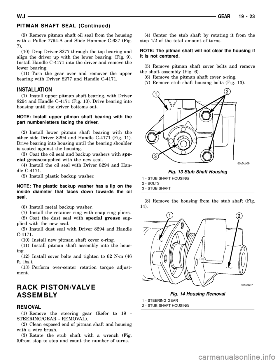
(7) Remove stub shaft housing bolts (Fig. 13).
(8) Remove the housing from the stub shaft (Fig.
14).
Fig. 13 Stub Shaft Housing
1 - STUB SHAFT HOUSING
2 - BOLTS
3 - STUB SHAFT
Fig. 14 Housing Removal
1 - STEERING GEAR
2 - STUB SHAFT HOUSING
WJGEAR 19 - 23
PITMAN SHAFT SEAL (Continued)
Page 1502 of 2199
INSTALLATION
(1) Lubricate new o-ring and teflon rings with
power steering fluid and install on the rack piston/
valve assembly.
(2) Lubricate the rack piston/valve assembly with
power steering fluid.
(3) Slide the assembly into the gear housing.
(4) Install new stub shaft housing o-rings and
install the housing. Tighten the housing bolts to 62
N´m (46 ft. lbs.).
(5) Install new o-ring on the pitman shaft cover.
(6) Install the pitman shaft into the gear housing.
(7) Install the pitman shaft cover bolts and tighten
to 62 N´m (46 ft. lbs.).
(8) Perform over-center rotation torque adjustment
(Refer to 19 - STEERING/GEAR - ADJUSTMENTS)..
(9) Install the steering gear (Refer to 19 - STEER-
ING/GEAR - INSTALLATION).
(10) Fill the power steering pump (Refer to 19 -
STEERING/PUMP - STANDARD PROCEDURE).
STUB SHAFT HOUSING
REMOVAL
NOTE: If stub shaft housing, seal or bearing is dam-
aged the housing must be replaced.
(1) Remove the steering gear (Refer to 19 -
STEERING/GEAR - REMOVAL).
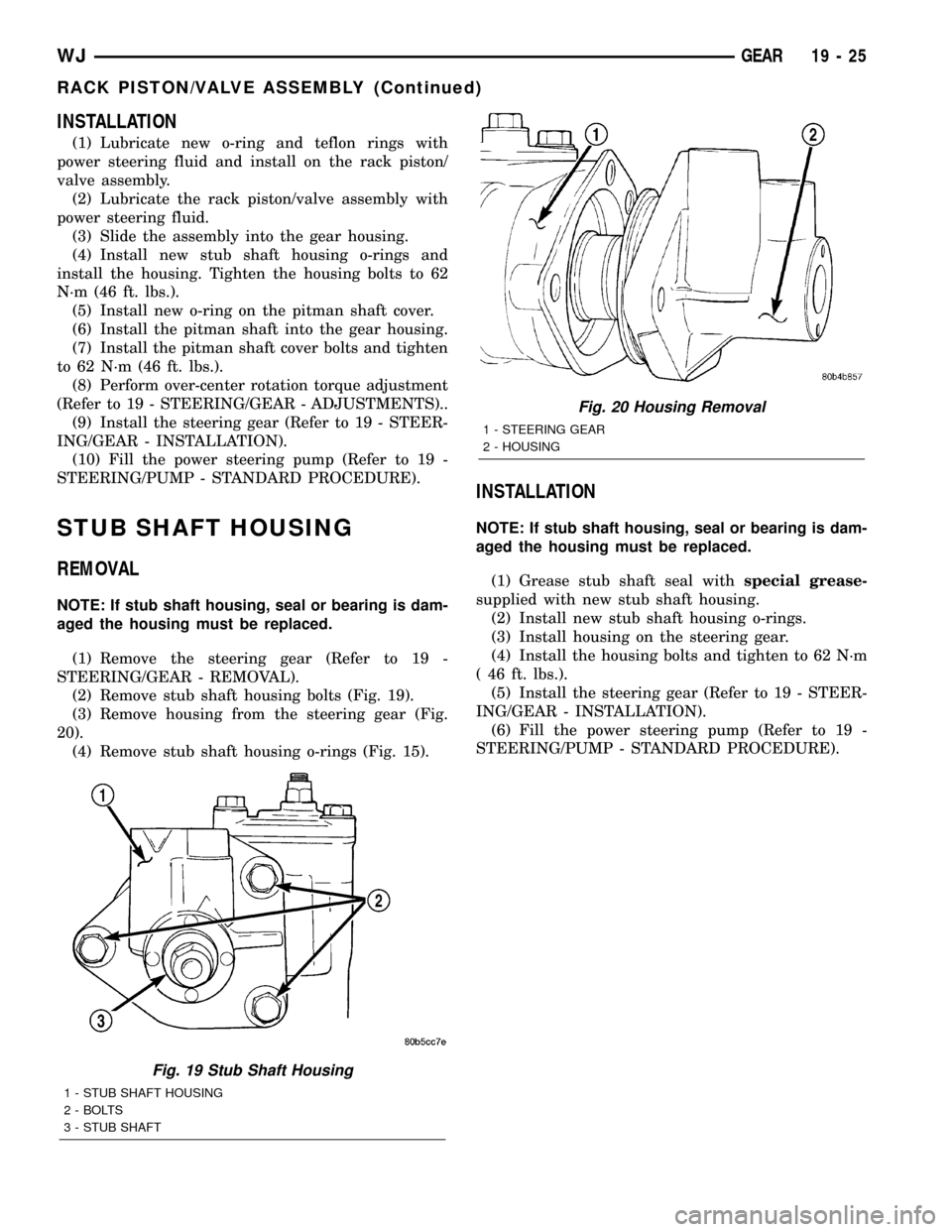
(2) Remove stub shaft housing bolts (Fig. 19).
(3) Remove housing from the steering gear (Fig.
20).
(4) Remove stub shaft housing o-rings (Fig. 15).
INSTALLATION
NOTE: If stub shaft housing, seal or bearing is dam-
aged the housing must be replaced.
(1) Grease stub shaft seal withspecial grease-
supplied with new stub shaft housing.
(2) Install new stub shaft housing o-rings.
(3) Install housing on the steering gear.
(4) Install the housing bolts and tighten to 62 N´m
( 46 ft. lbs.).
(5) Install the steering gear (Refer to 19 - STEER-
ING/GEAR - INSTALLATION).
(6) Fill the power steering pump (Refer to 19 -
STEERING/PUMP - STANDARD PROCEDURE).
Fig. 19 Stub Shaft Housing
1 - STUB SHAFT HOUSING
2 - BOLTS
3 - STUB SHAFT
Fig. 20 Housing Removal
1 - STEERING GEAR
2 - HOUSING
WJGEAR 19 - 25
RACK PISTON/VALVE ASSEMBLY (Continued)