2002 JEEP GRAND CHEROKEE Oil pan installation
[x] Cancel search: Oil pan installationPage 1301 of 2199
(3) Install intake manifold on the cylinder head
dowels.
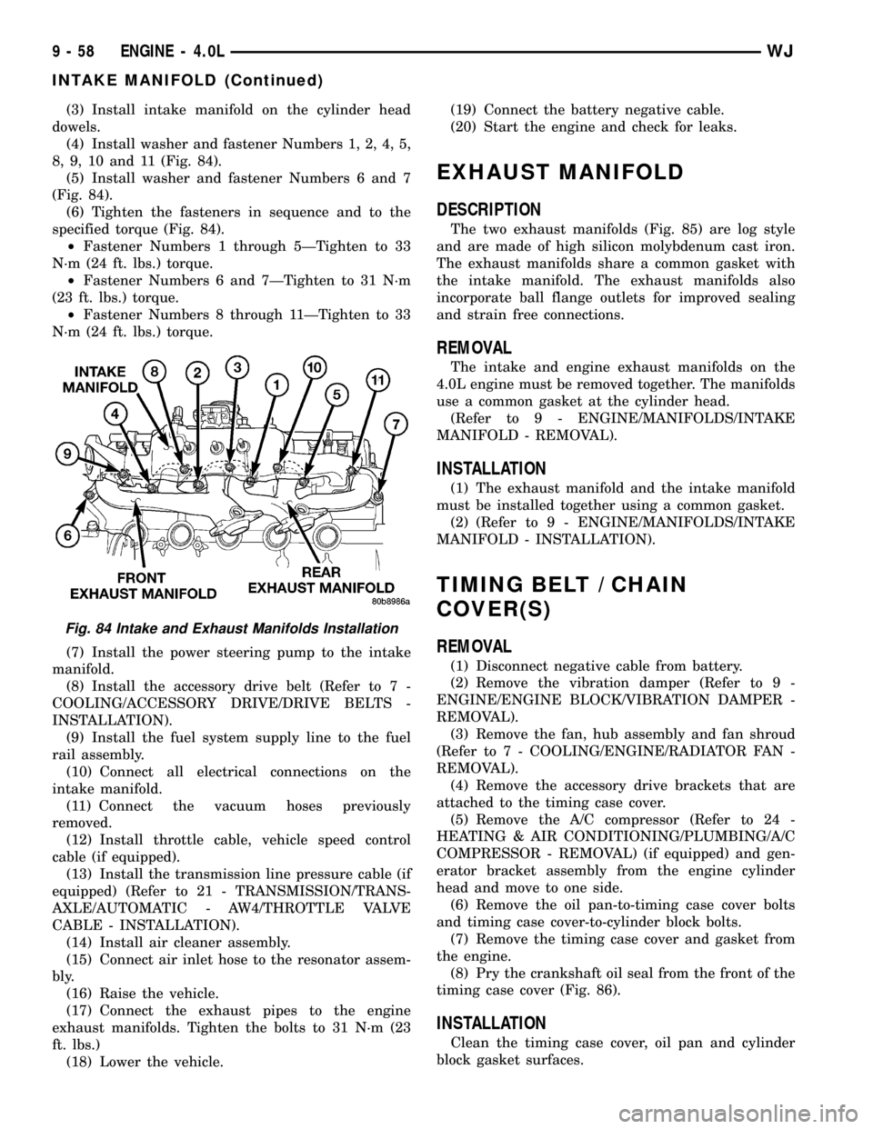
(4) Install washer and fastener Numbers 1, 2, 4, 5,
8, 9, 10 and 11 (Fig. 84).
(5) Install washer and fastener Numbers 6 and 7
(Fig. 84).
(6) Tighten the fasteners in sequence and to the
specified torque (Fig. 84).
²Fastener Numbers 1 through 5ÐTighten to 33
N´m (24 ft. lbs.) torque.
²Fastener Numbers 6 and 7ÐTighten to 31 N´m
(23 ft. lbs.) torque.
²Fastener Numbers 8 through 11ÐTighten to 33
N´m (24 ft. lbs.) torque.
(7) Install the power steering pump to the intake
manifold.
(8) Install the accessory drive belt (Refer to 7 -
COOLING/ACCESSORY DRIVE/DRIVE BELTS -
INSTALLATION).
(9) Install the fuel system supply line to the fuel
rail assembly.
(10) Connect all electrical connections on the
intake manifold.
(11) Connect the vacuum hoses previously
removed.
(12) Install throttle cable, vehicle speed control
cable (if equipped).
(13) Install the transmission line pressure cable (if
equipped) (Refer to 21 - TRANSMISSION/TRANS-
AXLE/AUTOMATIC - AW4/THROTTLE VALVE
CABLE - INSTALLATION).
(14) Install air cleaner assembly.
(15) Connect air inlet hose to the resonator assem-
bly.
(16) Raise the vehicle.
(17) Connect the exhaust pipes to the engine
exhaust manifolds. Tighten the bolts to 31 N´m (23
ft. lbs.)
(18) Lower the vehicle.(19) Connect the battery negative cable.
(20) Start the engine and check for leaks.
EXHAUST MANIFOLD
DESCRIPTION
The two exhaust manifolds (Fig. 85) are log style
and are made of high silicon molybdenum cast iron.
The exhaust manifolds share a common gasket with
the intake manifold. The exhaust manifolds also
incorporate ball flange outlets for improved sealing
and strain free connections.
REMOVAL
The intake and engine exhaust manifolds on the
4.0L engine must be removed together. The manifolds
use a common gasket at the cylinder head.
(Refer to 9 - ENGINE/MANIFOLDS/INTAKE
MANIFOLD - REMOVAL).
INSTALLATION
(1) The exhaust manifold and the intake manifold
must be installed together using a common gasket.
(2) (Refer to 9 - ENGINE/MANIFOLDS/INTAKE
MANIFOLD - INSTALLATION).
TIMING BELT / CHAIN
COVER(S)
REMOVAL
(1) Disconnect negative cable from battery.
(2) Remove the vibration damper (Refer to 9 -
ENGINE/ENGINE BLOCK/VIBRATION DAMPER -
REMOVAL).
(3) Remove the fan, hub assembly and fan shroud
(Refer to 7 - COOLING/ENGINE/RADIATOR FAN -
REMOVAL).
(4) Remove the accessory drive brackets that are
attached to the timing case cover.
(5) Remove the A/C compressor (Refer to 24 -
HEATING & AIR CONDITIONING/PLUMBING/A/C
COMPRESSOR - REMOVAL) (if equipped) and gen-
erator bracket assembly from the engine cylinder
head and move to one side.
(6) Remove the oil pan-to-timing case cover bolts
and timing case cover-to-cylinder block bolts.
(7) Remove the timing case cover and gasket from
the engine.
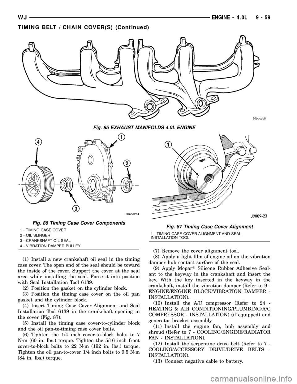
(8) Pry the crankshaft oil seal from the front of the
timing case cover (Fig. 86).
INSTALLATION
Clean the timing case cover, oil pan and cylinder
block gasket surfaces.
Fig. 84 Intake and Exhaust Manifolds Installation
9 - 58 ENGINE - 4.0LWJ
INTAKE MANIFOLD (Continued)
Page 1302 of 2199
(1) Install a new crankshaft oil seal in the timing
case cover. The open end of the seal should be toward
the inside of the cover. Support the cover at the seal
area while installing the seal. Force it into position
with Seal Installation Tool 6139.
(2) Position the gasket on the cylinder block.
(3) Position the timing case cover on the oil pan
gasket and the cylinder block.
(4) Insert Timing Case Cover Alignment and Seal
Installation Tool 6139 in the crankshaft opening in
the cover (Fig. 87).
(5) Install the timing case cover-to-cylinder block
and the oil pan-to-timing case cover bolts.
(6) Tighten the 1/4 inch cover-to-block bolts to 7
N´m (60 in. lbs.) torque. Tighten the 5/16 inch front
cover-to-block bolts to 22 N´m (192 in. lbs.) torque.
Tighten the oil pan-to-cover 1/4 inch bolts to 9.5 N´m
(84 in. lbs.) torque.(7) Remove the cover alignment tool.
(8) Apply a light film of engine oil on the vibration
damper hub contact surface of the seal.
(9) Apply MopartSilicone Rubber Adhesive Seal-
ant to the keyway in the crankshaft and insert the
key. With the key inserted in the keyway in the
crankshaft, install the vibration damper (Refer to 9 -
ENGINE/ENGINE BLOCK/VIBRATION DAMPER -
INSTALLATION).
(10) Install the A/C compressor (Refer to 24 -
HEATING & AIR CONDITIONING/PLUMBING/A/C
COMPRESSOR - INSTALLATION) (if equipped) and
generator bracket assembly.
(11) Install the engine fan, hub assembly and
shroud (Refer to 7 - COOLING/ENGINE/RADIATOR
FAN - INSTALLATION).
(12) Install the serpentine drive belt (Refer to 7 -
COOLING/ACCESSORY DRIVE/DRIVE BELTS -
INSTALLATION).
(13) Connect negative cable to battery.
Fig. 85 EXHAUST MANIFOLDS 4.0L ENGINE
Fig. 86 Timing Case Cover Components
1 - TIMING CASE COVER
2 - OIL SLINGER
3 - CRANKSHAFT OIL SEAL
4 - VIBRATION DAMPER PULLEYFig. 87 Timing Case Cover Alignment
1 - TIMING CASE COVER ALIGNMENT AND SEAL
INSTALLATION TOOL
WJENGINE - 4.0L 9 - 59
TIMING BELT / CHAIN COVER(S) (Continued)
Page 1305 of 2199
ROCKER ARM / ADJUSTER ASSEMBLY
DESCRIPTION........................107
REMOVAL............................107
INSTALLATION........................107
VALVE SPRINGS
DESCRIPTION........................108
VALVE STEM SEALS
DESCRIPTION........................108
ENGINE BLOCK
DESCRIPTION........................108
STANDARD PROCEDUREÐCYLINDER BORE
HONING...........................108
CLEANING...........................109
INSPECTION.........................109
CONNECTING ROD BEARINGS
STANDARD PROCEDURE - CONNECTING
ROD BEARING FITTING...............109
CRANKSHAFT
DESCRIPTION........................111
STANDARD PROCEDURE - MEASURING
CRANKSHAFT END PLAY..............111
REMOVAL............................112
INSPECTION..........................112
INSTALLATION........................112
CRANKSHAFT MAIN BEARINGS
STANDARD PROCEDUREÐCRANKSHAFT
MAIN BEARING - FITTING..............114
INSPECTION..........................115
CRANKSHAFT OIL SEAL - FRONT
REMOVAL............................115
INSTALLATION........................116
CRANKSHAFT OIL SEAL - REAR
REMOVAL............................117
INSTALLATION........................117
FLEX PLATE
REMOVAL............................118
INSTALLATION........................118
PISTON & CONNECTING ROD
DESCRIPTION........................118
STANDARD PROCEDUREÐPISTON FITTING . 118
REMOVAL............................118
CLEANING...........................119
INSPECTION..........................119
INSTALLATION........................120
PISTON RINGS
STANDARD PROCEDURE - PISTON RING
FITTING............................121
VIBRATION DAMPER
REMOVAL............................122
INSTALLATION........................123
STRUCTURAL COVER
DESCRIPTION........................124
OPERATION..........................124
REMOVAL............................124
INSTALLATION........................124
FRONT MOUNT
REMOVAL............................124INSTALLATION........................125
REAR MOUNT
REMOVAL............................125
INSTALLATION........................126
LUBRICATION
DESCRIPTION........................126
OPERATION..........................126
DIAGNOSIS AND TESTING
DIAGNOSIS AND TESTINGÐENGINE OIL
PRESSURE.........................128
DIAGNOSIS AND TESTINGÐREAR SEAL
AREA LEAKS........................128
DIAGNOSIS AND TESTINGÐENGINE OIL
LEAK..............................129
OIL
STANDARD PROCEDURE - ENGINE OIL....130
OIL FILTER
REMOVAL............................131
INSTALLATION........................132
OIL PAN
DESCRIPTION........................132
REMOVAL............................132
CLEANING...........................132
INSPECTION.........................132
INSTALLATION........................132
OIL PRESSURE SENSOR/SWITCH
DESCRIPTION........................133
OPERATION..........................133
REMOVAL............................133
INSTALLATION........................133
OIL PUMP
REMOVAL............................134
DISASSEMBLY........................134
CLEANING...........................134
INSPECTION.........................134
ASSEMBLY...........................135
INSTALLATION........................135
INTAKE MANIFOLD
DESCRIPTION........................136
DIAGNOSIS AND TESTINGÐINTAKE
MANIFOLD LEAKAGE.................136
REMOVAL............................136
CLEANING...........................137
INSPECTION.........................137
INSTALLATION........................137
EXHAUST MANIFOLD - LEFT
DESCRIPTION........................138
REMOVAL............................138
CLEANING...........................138
INSPECTION.........................138
INSTALLATION........................138
EXHAUST MANIFOLD - RIGHT
DESCRIPTION........................139
REMOVAL............................139
CLEANING...........................140
INSPECTION.........................141
INSTALLATION........................141
9 - 62 ENGINE - 4.7LWJ
Page 1334 of 2199
NOTE: When gripping the camshaft, place the pliers
on the tube portion of the camshaft only. Do not
grip the lobes or the sprocket areas.
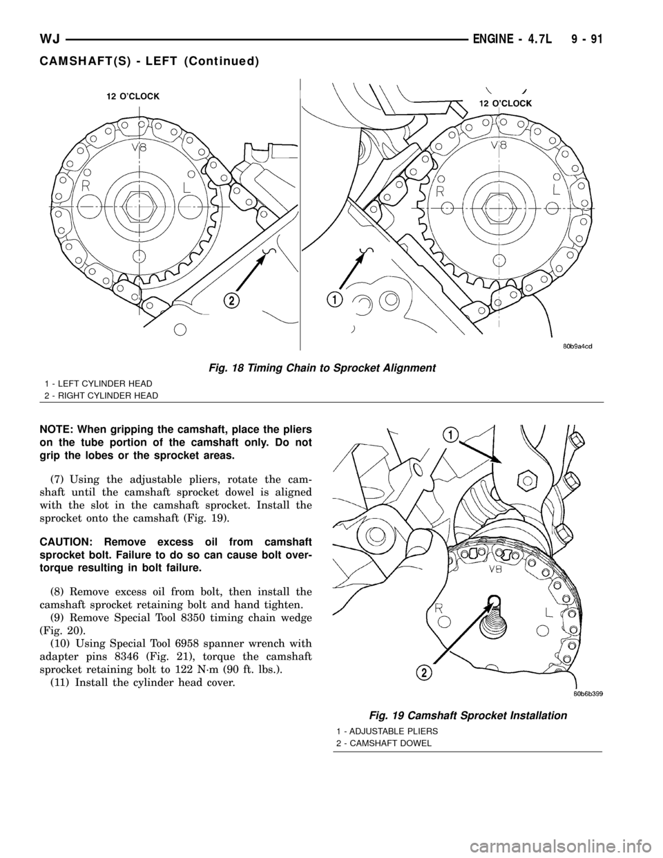
(7) Using the adjustable pliers, rotate the cam-
shaft until the camshaft sprocket dowel is aligned
with the slot in the camshaft sprocket. Install the
sprocket onto the camshaft (Fig. 19).
CAUTION: Remove excess oil from camshaft
sprocket bolt. Failure to do so can cause bolt over-
torque resulting in bolt failure.
(8) Remove excess oil from bolt, then install the
camshaft sprocket retaining bolt and hand tighten.
(9) Remove Special Tool 8350 timing chain wedge
(Fig. 20).
(10) Using Special Tool 6958 spanner wrench with
adapter pins 8346 (Fig. 21), torque the camshaft
sprocket retaining bolt to 122 N´m (90 ft. lbs.).
(11) Install the cylinder head cover.
Fig. 18 Timing Chain to Sprocket Alignment
1 - LEFT CYLINDER HEAD
2 - RIGHT CYLINDER HEAD
Fig. 19 Camshaft Sprocket Installation
1 - ADJUSTABLE PLIERS
2 - CAMSHAFT DOWEL
WJENGINE - 4.7L 9 - 91
CAMSHAFT(S) - LEFT (Continued)
Page 1345 of 2199
INSTALLATION
(1) Lubricate camshaft journals with clean engine
oil.
NOTE: Position the right side camshaft so that the
camshaft sprocket dowel is near the 10 o'clock
position, This will place the camshaft at the neutral
position easing the installation of the camshaft
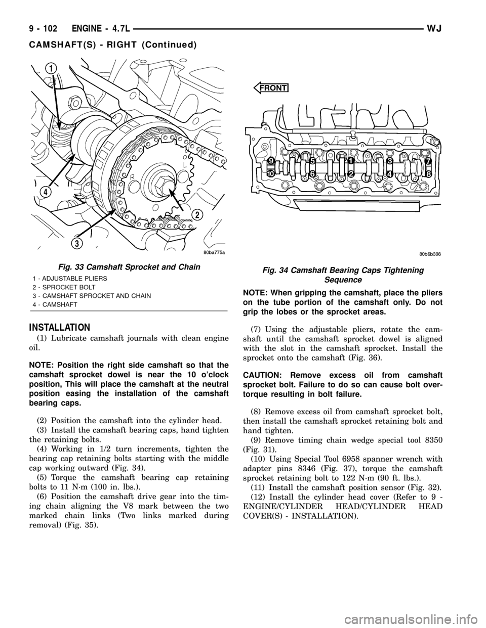
bearing caps.
(2) Position the camshaft into the cylinder head.
(3) Install the camshaft bearing caps, hand tighten
the retaining bolts.
(4) Working in 1/2 turn increments, tighten the
bearing cap retaining bolts starting with the middle
cap working outward (Fig. 34).
(5) Torque the camshaft bearing cap retaining
bolts to 11 N´m (100 in. lbs.).
(6) Position the camshaft drive gear into the tim-
ing chain aligning the V8 mark between the two
marked chain links (Two links marked during
removal) (Fig. 35).NOTE: When gripping the camshaft, place the pliers
on the tube portion of the camshaft only. Do not
grip the lobes or the sprocket areas.
(7) Using the adjustable pliers, rotate the cam-
shaft until the camshaft sprocket dowel is aligned
with the slot in the camshaft sprocket. Install the
sprocket onto the camshaft (Fig. 36).
CAUTION: Remove excess oil from camshaft
sprocket bolt. Failure to do so can cause bolt over-
torque resulting in bolt failure.
(8) Remove excess oil from camshaft sprocket bolt,
then install the camshaft sprocket retaining bolt and
hand tighten.
(9) Remove timing chain wedge special tool 8350
(Fig. 31).
(10) Using Special Tool 6958 spanner wrench with
adapter pins 8346 (Fig. 37), torque the camshaft
sprocket retaining bolt to 122 N´m (90 ft. lbs.).
(11) Install the camshaft position sensor (Fig. 32).
(12) Install the cylinder head cover (Refer to 9 -
ENGINE/CYLINDER HEAD/CYLINDER HEAD
COVER(S) - INSTALLATION).
Fig. 33 Camshaft Sprocket and Chain
1 - ADJUSTABLE PLIERS
2 - SPROCKET BOLT
3 - CAMSHAFT SPROCKET AND CHAIN
4 - CAMSHAFTFig. 34 Camshaft Bearing Caps Tightening
Sequence
9 - 102 ENGINE - 4.7LWJ
CAMSHAFT(S) - RIGHT (Continued)
Page 1355 of 2199
REMOVAL
NOTE: To remove the crankshaft from the engine,
the engine must be removed from the vehicle.
(1) Remove the engine. (Refer to 9 - ENGINE -
REMOVAL).
(2) Remove the engine oil pump.(Refer to 9 -
ENGINE/LUBRICATION/OIL PUMP - REMOVAL).
CAUTION: DO NOT pry on the oil pan gasket when
removing the oil pan, The oil pan gasket is mounted
to the cylinder block in three locations and will
remain attached to block when removing oil pan.
Gasket can not be removed with oil pan.
(3) Remove oil pan. (Refer to 9 - ENGINE/LUBRI-
CATION/OIL PAN - REMOVAL).
(4) Remove the oil pump pickup tube and oil pan
gasket /windage tray.
(5) Remove the bedplate mounting bolts. Note the
location of the three stud bolts for installation.
(6) Remove the connecting rods from the crank-
shaft.
CAUTION: The bedplate to cylinder block mating
surface is a critical sealing surface. Do not pry on
or damage this surface in anyway.
NOTE: The bedplate contains the lower main bear-
ing halves. Use care when handling bedplate as not
to drop or damage bearing halves. Installing main
bearing halves in the wrong position will cause
sever damage to the crankshaft.
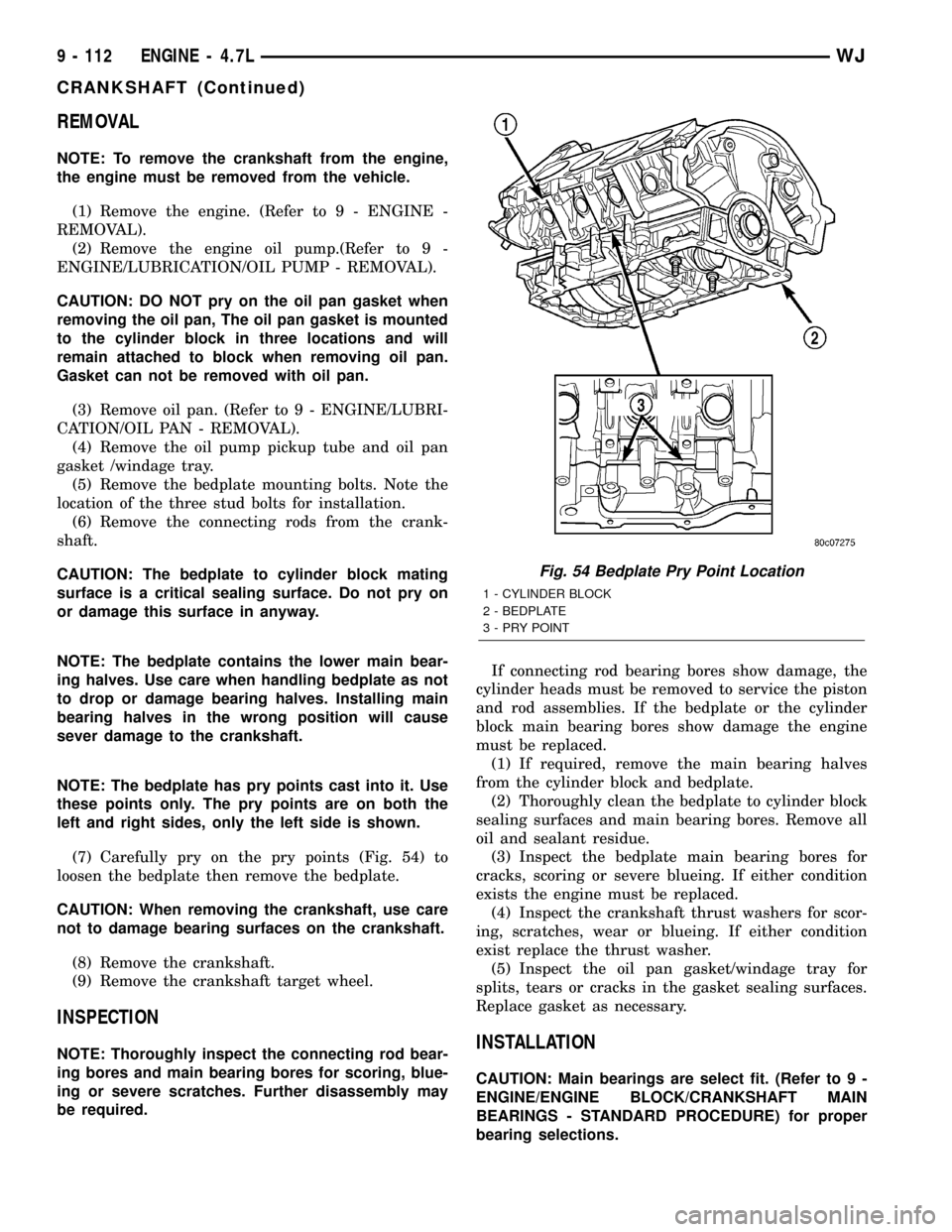
NOTE: The bedplate has pry points cast into it. Use
these points only. The pry points are on both the
left and right sides, only the left side is shown.
(7) Carefully pry on the pry points (Fig. 54) to
loosen the bedplate then remove the bedplate.
CAUTION: When removing the crankshaft, use care
not to damage bearing surfaces on the crankshaft.
(8) Remove the crankshaft.
(9) Remove the crankshaft target wheel.
INSPECTION
NOTE: Thoroughly inspect the connecting rod bear-
ing bores and main bearing bores for scoring, blue-
ing or severe scratches. Further disassembly may
be required.If connecting rod bearing bores show damage, the
cylinder heads must be removed to service the piston
and rod assemblies. If the bedplate or the cylinder
block main bearing bores show damage the engine
must be replaced.
(1) If required, remove the main bearing halves
from the cylinder block and bedplate.
(2) Thoroughly clean the bedplate to cylinder block
sealing surfaces and main bearing bores. Remove all
oil and sealant residue.
(3) Inspect the bedplate main bearing bores for
cracks, scoring or severe blueing. If either condition
exists the engine must be replaced.
(4) Inspect the crankshaft thrust washers for scor-
ing, scratches, wear or blueing. If either condition
exist replace the thrust washer.
(5) Inspect the oil pan gasket/windage tray for
splits, tears or cracks in the gasket sealing surfaces.
Replace gasket as necessary.INSTALLATION
CAUTION: Main bearings are select fit. (Refer to 9 -
ENGINE/ENGINE BLOCK/CRANKSHAFT MAIN
BEARINGS - STANDARD PROCEDURE) for proper
bearing selections.
Fig. 54 Bedplate Pry Point Location
1 - CYLINDER BLOCK
2 - BEDPLATE
3 - PRY POINT
9 - 112 ENGINE - 4.7LWJ
CRANKSHAFT (Continued)
Page 1357 of 2199
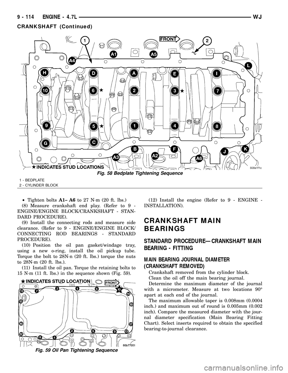
²Tighten boltsA1± A6to 27 N´m (20 ft. lbs.)
(8) Measure crankshaft end play. (Refer to 9 -
ENGINE/ENGINE BLOCK/CRANKSHAFT - STAN-
DARD PROCEDURE).
(9) Install the connecting rods and measure side
clearance. (Refer to 9 - ENGINE/ENGINE BLOCK/
CONNECTING ROD BEARINGS - STANDARD
PROCEDURE).
(10) Position the oil pan gasket/windage tray,
using a new o-ring, install the oil pickup tube.
Torque the bolt to 28N´n (20 ft. lbs.) torque the nuts
to 28N´m (20 ft. lbs.).
(11)
Install the oil pan. Torque the retaining bolts to
15 N´m (11 ft. lbs.) in the sequence shown (Fig. 59).
(12) Install the engine (Refer to 9 - ENGINE -
INSTALLATION).
CRANKSHAFT MAIN
BEARINGS
STANDARD PROCEDUREÐCRANKSHAFT MAIN
BEARING - FITTING
MAIN BEARING JOURNAL DIAMETER
(CRANKSHAFT REMOVED)
Crankshaft removed from the cylinder block.
Clean the oil off the main bearing journal.
Determine the maximum diameter of the journal
with a micrometer. Measure at two locations 90É
apart at each end of the journal.
The maximum allowable taper is 0.008mm (0.0004
inch.) and maximum out of round is 0.005mm (0.002
inch). Compare the measured diameter with the jour-
nal diameter specification (Main Bearing Fitting
Chart). Select inserts required to obtain the specified
bearing-to-journal clearance.
Fig. 58 Bedplate Tightening Sequence
1 - BEDPLATE
2 - CYLINDER BLOCK
Fig. 59 Oil Pan Tightening Sequence
9 - 114 ENGINE - 4.7LWJ
CRANKSHAFT (Continued)
Page 1361 of 2199
FLEX PLATE
REMOVAL
(1) Remove the transmission.
(2) Remove the bolts and flexplate.
INSTALLATION
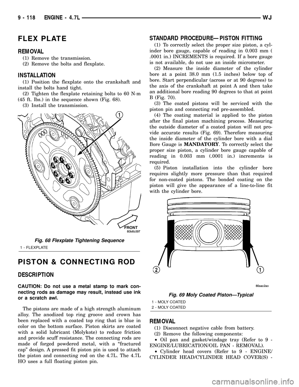
(1) Position the flexplate onto the crankshaft and
install the bolts hand tight.
(2) Tighten the flexplate retaining bolts to 60 N´m
(45 ft. lbs.) in the sequence shown (Fig. 68).
(3) Install the transmission.
PISTON & CONNECTING ROD
DESCRIPTION
CAUTION: Do not use a metal stamp to mark con-
necting rods as damage may result, instead use ink
or a scratch awl.
The pistons are made of a high strength aluminum
alloy. The anodized top ring groove and crown has
been replaced with a coated top ring that is blue in
color on the bottom surface. Piston skirts are coated
with a solid lubricant (Molykote) to reduce friction
and provide scuff resistance. The connecting rods are
made of forged powdered metal, with a ªfractured
capº design. A pressed fit piston pin is used to attach
the piston and connecting rod on the 4.7L. The 4.7L
HO uses a full floating piston pin.
STANDARD PROCEDUREÐPISTON FITTING
(1) To correctly select the proper size piston, a cyl-
inder bore gauge, capable of reading in 0.003 mm (
.0001 in.) INCREMENTS is required. If a bore gauge
is not available, do not use an inside micrometer.
(2) Measure the inside diameter of the cylinder
bore at a point 38.0 mm (1.5 inches) below top of
bore. Start perpendicular (across or at 90 degrees) to
the axis of the crankshaft at point A and then take
an additional bore reading 90 degrees to that at point
B (Fig. 70).
(3) The coated pistons will be serviced with the
piston pin and connecting rod pre-assembled.
(4) The coating material is applied to the piston
after the final piston machining process. Measuring
the outside diameter of a coated piston will not pro-
vide accurate results (Fig. 69). Therefore measuring
the inside diameter of the cylinder bore with a dial
Bore Gauge isMANDATORY. To correctly select the
proper size piston, a cylinder bore gauge capable of
reading in 0.003 mm (.0001 in.) increments is
required.
(5) Piston installation into the cylinder bore
requires slightly more pressure than that required
for non-coated pistons. The bonded coating on the
piston will give the appearance of a line-to-line fit
with the cylinder bore.
REMOVAL
(1) Disconnect negative cable from battery.
(2) Remove the following components:
²Oil pan and gasket/windage tray (Refer to 9 -
ENGINE/LUBRICATION/OIL PAN - REMOVAL).
²Cylinder head covers (Refer to 9 - ENGINE/
CYLINDER HEAD/CYLINDER HEAD COVER(S) -
Fig. 68 Flexplate Tightening Sequence
1 - FLEXPLATE
Fig. 69 Moly Coated PistonÐTypical
1 - MOLY COATED
2 - MOLY COATED
9 - 118 ENGINE - 4.7LWJ