2002 JEEP GRAND CHEROKEE HAZARD
[x] Cancel search: HAZARDPage 556 of 2199

OPERATION
The multistage driver airbag is deployed by electri-
cal signals generated by the Airbag Control Module
(ACM) through the driver airbag squib 1 and squib 2
circuits to the two initiators in the airbag inflator. By
using two initiators, the airbag can be deployed at
multiple levels of force. The force level is controlled
by the ACM to suit the monitored impact conditions
by providing one of four delay intervals between the
electrical signals provided to the two initiators. The
longer the delay between these signals, the less force-
fully the airbag will deploy. When the ACM sends the
proper electrical signals to each initiator, the electri-
cal energy generates enough heat to initiate a small
pyrotechnic charge which, in turn ignites chemical
pellets within the inflator. Once ignited, these chem-
ical pellets burn rapidly and produce a large quantity
of nitrogen gas. The inflator is sealed to the back of
the airbag housing and a diffuser in the inflator
directs all of the nitrogen gas into the airbag cush-
ion, causing the cushion to inflate. As the cushion
inflates, the driver airbag trim cover will split at pre-
determined breakout lines, then fold back out of the
way along with the horn switch and tray unit. Fol-
lowing an airbag deployment, the airbag cushion
quickly deflates by venting the nitrogen gas towards
the instrument panel through vent holes within the
fabric used to construct the back (steering wheel
side) panel of the airbag cushion.
Some of the chemicals used to create the nitrogen
gas may be considered hazardous while in their solid
state before they are burned, but they are securely
sealed within the airbag inflator. Typically, both ini-
tiators are used and all potentially hazardous chem-
icals are burned during an airbag deployment event.
However, it is possible for only one initiator to be
used during a deployment due to an airbag system
fault; therefore, it is necessary to always confirm
that both initiators have been used in order to avoid
the improper disposal of potentially live pyrotechnic
or hazardous materials. (Refer to 8 - ELECTRICAL/
RESTRAINTS - STANDARD PROCEDURE - SER-
VICE AFTER A SUPPLEMENTAL RESTRAINT
DEPLOYMENT). The nitrogen gas that is produced
when the chemicals are burned is harmless. How-
ever, a small amount of residue from the burned
chemicals may cause some temporary discomfort if it
contacts the skin, eyes, or breathing passages. If skin
or eye irritation is noted, rinse the affected area with
plenty of cool, clean water. If breathing passages are
irritated, move to another area where there is plenty
of clean, fresh air to breath. If the irritation is not
alleviated by these actions, contact a physician.
REMOVAL
The following procedure is for replacement of a
faulty or damaged driver airbag. If the airbag is
faulty or damaged, but not deployed, review the rec-
ommended procedures for handling non-deployed
supplemental restraints. (Refer to 8 - ELECTRICAL/
RESTRAINTS - STANDARD PROCEDURE - HAN-
DLING NON-DEPLOYED SUPPLEMENTAL
RESTRAINTS). If the driver airbag has been
deployed, review the recommended procedures for
service after a supplemental restraint deployment
before removing the airbag from the vehicle. (Refer to
8 - ELECTRICAL/RESTRAINTS - STANDARD PRO-
CEDURE - SERVICE AFTER A SUPPLEMENTAL
RESTRAINT DEPLOYMENT).
WARNING: ON VEHICLES EQUIPPED WITH AIR-
BAGS, DISABLE THE SUPPLEMENTAL RESTRAINT
SYSTEM BEFORE ATTEMPTING ANY STEERING
WHEEL, STEERING COLUMN, DRIVER AIRBAG,
PASSENGER AIRBAG, FRONT IMPACT SENSOR,
SIDE IMPACT SENSOR, SIDE CURTAIN AIRBAG, OR
INSTRUMENT PANEL COMPONENT DIAGNOSIS OR
SERVICE. DISCONNECT AND ISOLATE THE BAT-
TERY NEGATIVE (GROUND) CABLE, THEN WAIT
TWO MINUTES FOR THE SYSTEM CAPACITOR TO
DISCHARGE BEFORE PERFORMING FURTHER
DIAGNOSIS OR SERVICE. THIS IS THE ONLY SURE
WAY TO DISABLE THE SUPPLEMENTAL
RESTRAINT SYSTEM. FAILURE TO TAKE THE
PROPER PRECAUTIONS COULD RESULT IN ACCI-
DENTAL AIRBAG DEPLOYMENT AND POSSIBLE
PERSONAL INJURY.
WARNING: WHEN REMOVING A DEPLOYED AIR-
BAG, RUBBER GLOVES, EYE PROTECTION, AND A
LONG-SLEEVED SHIRT SHOULD BE WORN. THERE
MAY BE DEPOSITS ON THE AIRBAG CUSHION AND
OTHER INTERIOR SURFACES. IN LARGE DOSES,
THESE DEPOSITS MAY CAUSE IRRITATION TO THE
SKIN AND EYES.
(1) Disconnect and isolate the battery negative
cable. Wait two minutes for the system capacitor to
discharge before further service.
(2) From the underside of the steering wheel,
remove the two screws that secure the driver airbag
to the steering wheel armature (Fig. 19).
(3) Pull the driver airbag away from the steering
wheel far enough to access the three electrical con-
nections on the back of the airbag housing.
(4) Disconnect the steering wheel wire harness
connector for the horn switch from the horn switch
feed pigtail wire connector, which is located on the
back of the driver airbag housing.
WJRESTRAINTS 8O - 19
DRIVER AIRBAG (Continued)
Page 632 of 2199

switch mounting housing. Tighten the screws to 2.5
N´m (22 in. lbs.).
(3) Reconnect the instrument panel wire harness
connector for the right multi-function switch to the
switch connector receptacle.
(4) Position the lower tilting steering column
shroud to the underside of the steering column (Fig.
18).
(5) Install and tighten the screw that secures the
lower tilting steering column shroud to the multi-
function switch mounting housing. Tighten the screw
to 1.9 N´m (17 in. lbs.).
(6) Position the upper tilting column shroud over
the steering column with the hazard warning switch
button inserted through the hole in the upper surface
of the shroud. Align the upper tilting steering column
shroud to the lower shroud and snap the two shroud
halves together.
(7) Reconnect the battery negative cable.
WASHER FLUID LEVEL
SWITCH
DESCRIPTION
The washer fluid level switch is a single pole, sin-
gle throw reed-type switch mounted near the front of
the washer reservoir, forward of the two washer
pump/motors (Fig. 20). Only the molded plastic
switch mounting flange and connector receptacle are
visible when the switch is installed in the reservoir.A short nipple formation extends from the inner sur-
face of the switch mounting flange, and a barb on the
nipple near the switch mounting flange is press-fit
into a rubber grommet seal installed in the mounting
hole of the reservoir. A small plastic float pivots on
the end of a bracket that extends from the switch
nipple formation. Within the float is a small magnet,
which actuates the reed switch. The washer fluid
level switch cannot be adjusted or repaired. If faulty
or damaged, the switch must be replaced.
OPERATION
The washer fluid level switch uses a pivoting,
oblong float to monitor the level of the washer fluid
in the washer reservoir. The float contains a small
magnet. When the float pivots, the changing proxim-
ity of its magnetic field will cause the contacts of the
small, stationary reed switch to open or close. When
the fluid level in the washer reservoir is at or above
the float level, the float moves to a vertical position
and the switch contacts open. When the fluid level in
the washer reservoir falls below the pivoting float,
the float moves to a horizontal position and the
switch contacts close. The switch is connected to the
vehicle electrical system through a dedicated take
out and connector of the left headlamp and dash wire
harness. The switch receives a five volt reference sig-
nal from the Body Control Module (BCM) through
the washer fluid switch output circuit. The switch is
grounded at all times through another take out of
the left headlamp and dash wire harness with a sin-
gle eyelet terminal connector that is secured under a
ground screw near the top of the left front fender
inner shield in the engine compartment.
When the switch closes, the BCM senses the volt-
age change on the circuit. The BCM is programmed
to send low washer fluid messages to the Electronic
Vehicle Information Center (EVIC) over the Program-
mable Communications Interface (PCI) data bus. The
EVIC is programmed to respond to this message by
displaying the Washer Fluid Low warning and send-
ing a chime request message back to the BCM over
the PCI data bus. Then the BCM generates an audi-
ble chime tone warning. A resistor within the washer
fluid level switch allows the BCM to monitor and
diagnose this circuit. The BCM will store a Diagnos-
tic Trouble Code (DTC) for any fault that it detects.
For retrieval of this fault information and further
diagnosis of the washer fluid level switch, the BCM,
the EVIC, the PCI data bus, the BCM message out-
puts to the EVIC that control the Low Washer Fluid
indicator, or the EVIC message outputs to the BCM
that control chime service, a DRBIIItscan tool and
the appropriate diagnostic information are required.
Fig. 20 Washer Fluid Level Switch (Viewed from
Bottom of Reservoir)
1 - REAR WASHER PUMP/MOTOR
2 - FRONT WASHER PUMP/MOTOR
3 - WASHER FLUID LEVEL SWITCH
WJFRONT WIPERS/WASHERS 8R - 25
RIGHT MULTI-FUNCTION SWITCH (Continued)
Page 1133 of 2199

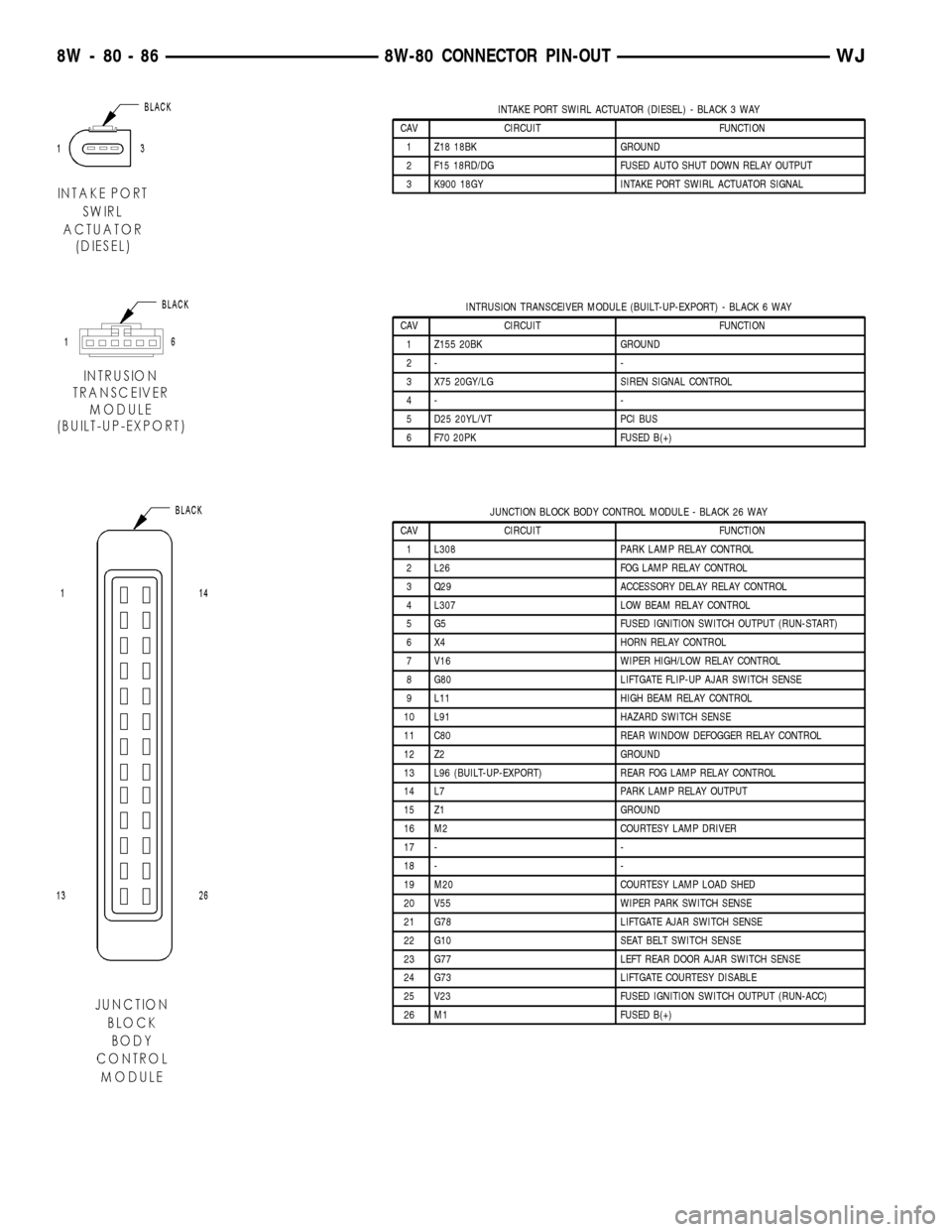
INTAKE PORT SWIRL ACTUATOR (DIESEL) - BLACK 3 WAY
CAV CIRCUIT FUNCTION
1 Z18 18BK GROUND
2 F15 18RD/DG FUSED AUTO SHUT DOWN RELAY OUTPUT
3 K900 18GY INTAKE PORT SWIRL ACTUATOR SIGNAL
INTRUSION TRANSCEIVER MODULE (BUILT-UP-EXPORT) - BLACK 6 WAY
CAV CIRCUIT FUNCTION
1 Z155 20BK GROUND
2- -
3 X75 20GY/LG SIREN SIGNAL CONTROL
4- -
5 D25 20YL/VT PCI BUS
6 F70 20PK FUSED B(+)
JUNCTION BLOCK BODY CONTROL MODULE - BLACK 26 WAY
CAV CIRCUIT FUNCTION
1 L308 PARK LAMP RELAY CONTROL
2 L26 FOG LAMP RELAY CONTROL
3 Q29 ACCESSORY DELAY RELAY CONTROL
4 L307 LOW BEAM RELAY CONTROL
5 G5 FUSED IGNITION SWITCH OUTPUT (RUN-START)
6 X4 HORN RELAY CONTROL
7 V16 WIPER HIGH/LOW RELAY CONTROL
8 G80 LIFTGATE FLIP-UP AJAR SWITCH SENSE
9 L11 HIGH BEAM RELAY CONTROL
10 L91 HAZARD SWITCH SENSE
11 C80 REAR WINDOW DEFOGGER RELAY CONTROL
12 Z2 GROUND
13 L96 (BUILT-UP-EXPORT) REAR FOG LAMP RELAY CONTROL
14 L7 PARK LAMP RELAY OUTPUT
15 Z1 GROUND
16 M2 COURTESY LAMP DRIVER
17 - -
18 - -
19 M20 COURTESY LAMP LOAD SHED
20 V55 WIPER PARK SWITCH SENSE
21 G78 LIFTGATE AJAR SWITCH SENSE
22 G10 SEAT BELT SWITCH SENSE
23 G77 LEFT REAR DOOR AJAR SWITCH SENSE
24 G73 LIFTGATE COURTESY DISABLE
25 V23 FUSED IGNITION SWITCH OUTPUT (RUN-ACC)
26 M1 FUSED B(+)
8W - 80 - 86 8W-80 CONNECTOR PIN-OUTWJ
Page 1137 of 2199

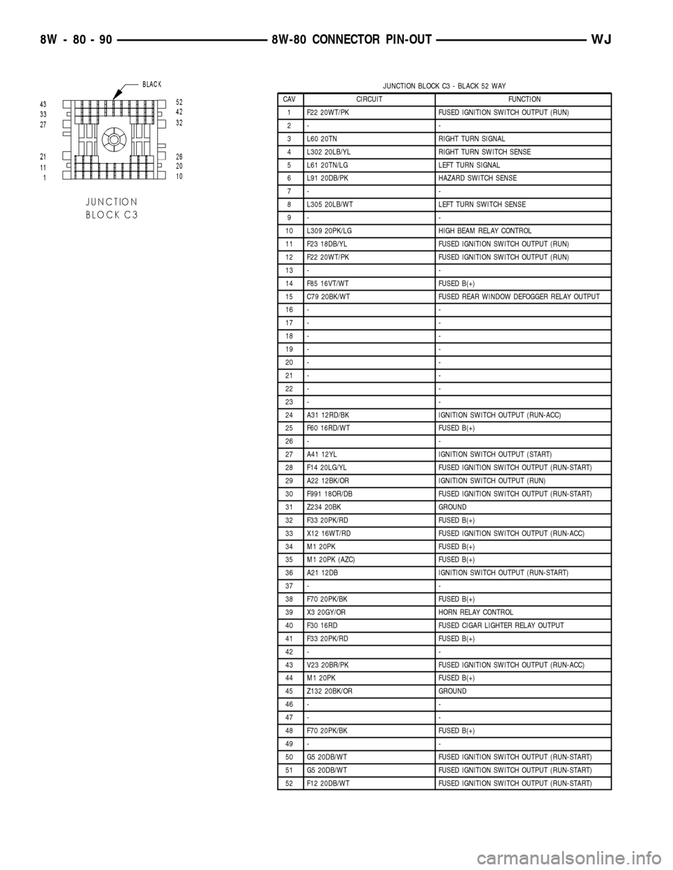
JUNCTION BLOCK C3 - BLACK 52 WAY
CAV CIRCUIT FUNCTION
1 F22 20WT/PK FUSED IGNITION SWITCH OUTPUT (RUN)
2- -
3 L60 20TN RIGHT TURN SIGNAL
4 L302 20LB/YL RIGHT TURN SWITCH SENSE
5 L61 20TN/LG LEFT TURN SIGNAL
6 L91 20DB/PK HAZARD SWITCH SENSE
7- -
8 L305 20LB/WT LEFT TURN SWITCH SENSE
9- -
10 L309 20PK/LG HIGH BEAM RELAY CONTROL
11 F23 18DB/YL FUSED IGNITION SWITCH OUTPUT (RUN)
12 F22 20WT/PK FUSED IGNITION SWITCH OUTPUT (RUN)
13 - -
14 F85 16VT/WT FUSED B(+)
15 C79 20BK/WT FUSED REAR WINDOW DEFOGGER RELAY OUTPUT
16 - -
17 - -
18 - -
19 - -
20 - -
21 - -
22 - -
23 - -
24 A31 12RD/BK IGNITION SWITCH OUTPUT (RUN-ACC)
25 F60 16RD/WT FUSED B(+)
26 - -
27 A41 12YL IGNITION SWITCH OUTPUT (START)
28 F14 20LG/YL FUSED IGNITION SWITCH OUTPUT (RUN-START)
29 A22 12BK/OR IGNITION SWITCH OUTPUT (RUN)
30 F991 18OR/DB FUSED IGNITION SWITCH OUTPUT (RUN-START)
31 Z234 20BK GROUND
32 F33 20PK/RD FUSED B(+)
33 X12 16WT/RD FUSED IGNITION SWITCH OUTPUT (RUN-ACC)
34 M1 20PK FUSED B(+)
35 M1 20PK (AZC) FUSED B(+)
36 A21 12DB IGNITION SWITCH OUTPUT (RUN-START)
37 - -
38 F70 20PK/BK FUSED B(+)
39 X3 20GY/OR HORN RELAY CONTROL
40 F30 16RD FUSED CIGAR LIGHTER RELAY OUTPUT
41 F33 20PK/RD FUSED B(+)
42 - -
43 V23 20BR/PK FUSED IGNITION SWITCH OUTPUT (RUN-ACC)
44 M1 20PK FUSED B(+)
45 Z132 20BK/OR GROUND
46 - -
47 - -
48 F70 20PK/BK FUSED B(+)
49 - -
50 G5 20DB/WT FUSED IGNITION SWITCH OUTPUT (RUN-START)
51 G5 20DB/WT FUSED IGNITION SWITCH OUTPUT (RUN-START)
52 F12 20DB/WT FUSED IGNITION SWITCH OUTPUT (RUN-START)
8W - 80 - 90 8W-80 CONNECTOR PIN-OUTWJ
Page 1142 of 2199

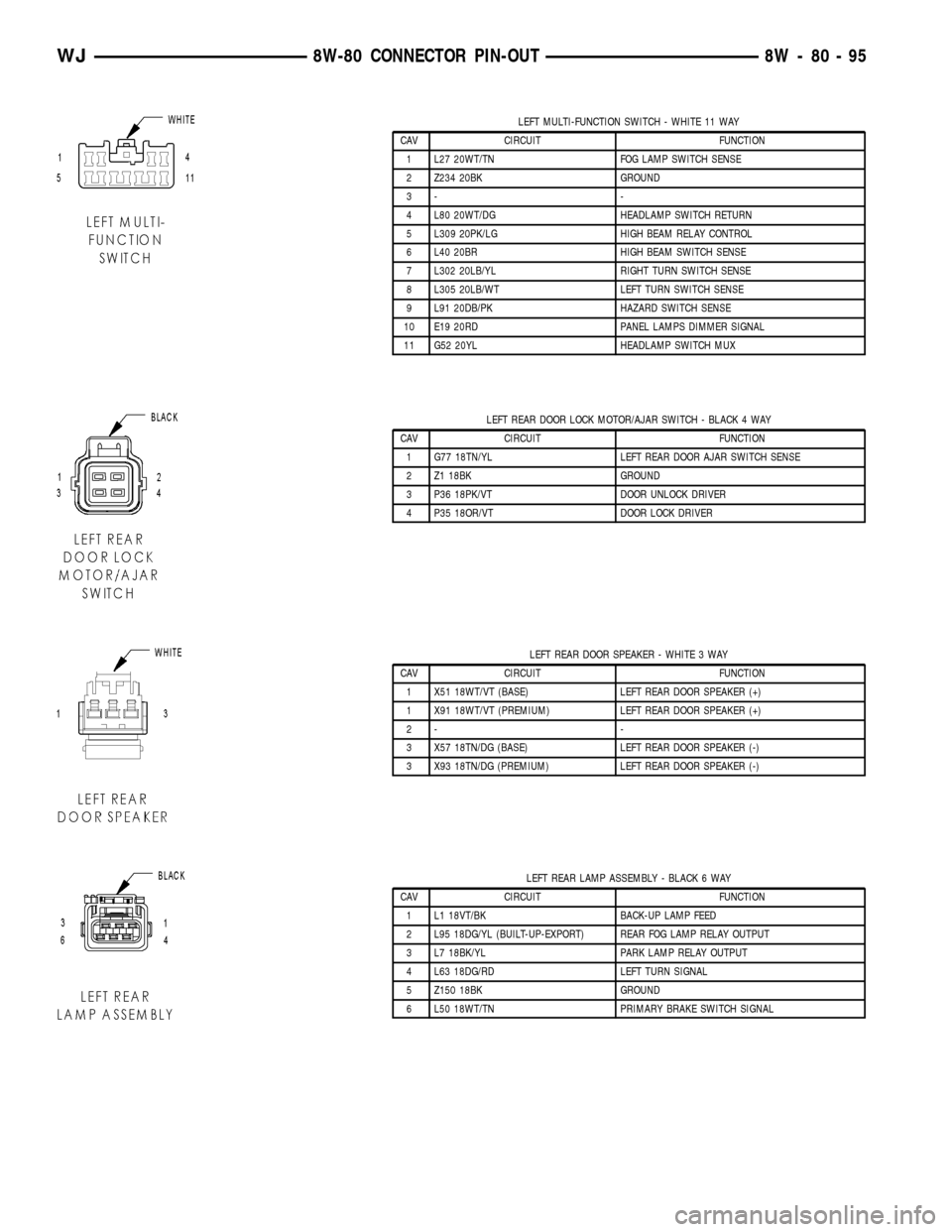
LEFT MULTI-FUNCTION SWITCH - WHITE 11 WAY
CAV CIRCUIT FUNCTION
1 L27 20WT/TN FOG LAMP SWITCH SENSE
2 Z234 20BK GROUND
3- -
4 L80 20WT/DG HEADLAMP SWITCH RETURN
5 L309 20PK/LG HIGH BEAM RELAY CONTROL
6 L40 20BR HIGH BEAM SWITCH SENSE
7 L302 20LB/YL RIGHT TURN SWITCH SENSE
8 L305 20LB/WT LEFT TURN SWITCH SENSE
9 L91 20DB/PK HAZARD SWITCH SENSE
10 E19 20RD PANEL LAMPS DIMMER SIGNAL
11 G52 20YL HEADLAMP SWITCH MUX
LEFT REAR DOOR LOCK MOTOR/AJAR SWITCH - BLACK 4 WAY
CAV CIRCUIT FUNCTION
1 G77 18TN/YL LEFT REAR DOOR AJAR SWITCH SENSE
2 Z1 18BK GROUND
3 P36 18PK/VT DOOR UNLOCK DRIVER
4 P35 18OR/VT DOOR LOCK DRIVER
LEFT REAR DOOR SPEAKER - WHITE 3 WAY
CAV CIRCUIT FUNCTION
1 X51 18WT/VT (BASE) LEFT REAR DOOR SPEAKER (+)
1 X91 18WT/VT (PREMIUM) LEFT REAR DOOR SPEAKER (+)
2- -
3 X57 18TN/DG (BASE) LEFT REAR DOOR SPEAKER (-)
3 X93 18TN/DG (PREMIUM) LEFT REAR DOOR SPEAKER (-)
LEFT REAR LAMP ASSEMBLY - BLACK 6 WAY
CAV CIRCUIT FUNCTION
1 L1 18VT/BK BACK-UP LAMP FEED
2 L95 18DG/YL (BUILT-UP-EXPORT) REAR FOG LAMP RELAY OUTPUT
3 L7 18BK/YL PARK LAMP RELAY OUTPUT
4 L63 18DG/RD LEFT TURN SIGNAL
5 Z150 18BK GROUND
6 L50 18WT/TN PRIMARY BRAKE SWITCH SIGNAL
WJ8W-80 CONNECTOR PIN-OUT 8W - 80 - 95
Page 1373 of 2199

If the leakage occurs at the crankshaft rear oil seal
area:
(1) Disconnect the battery.
(2) Raise the vehicle.
(3) Remove torque converter or clutch housing
cover and inspect rear of block for evidence of oil.
Use a black light to check for the oil leak:
(a) Circular spray pattern generally indicates
seal leakage or crankshaft damage.
(b) Where leakage tends to run straight down,
possible causes are a porous block, distributor seal,
camshaft bore cup plugs oil galley pipe plugs, oil
filter runoff, and main bearing cap to cylinder
block mating surfaces.
(4) If no leaks are detected, pressurize the crank-
case as outlined in the, Inspection (Engine oil Leaks
in general)
CAUTION: Do not exceed 20.6 kPa (3 psi).
(5) If the leak is not detected, very slowly turn the
crankshaft and watch for leakage. If a leak is
detected between the crankshaft and seal while
slowly turning the crankshaft, it is possible the
crankshaft seal surface is damaged. The seal area on
the crankshaft could have minor nicks or scratches
that can be polished out with emery cloth.
CAUTION: Use extreme caution when crankshaft
polishing is necessary to remove minor nicks and
scratches. The crankshaft seal flange is especially
machined to complement the function of the rear oil
seal.
(6) For bubbles that remain steady with shaft
rotation, no further inspection can be done until dis-
assembled.
OIL
STANDARD PROCEDURE - ENGINE OIL
WARNING: NEW OR USED ENGINE OIL CAN BE
IRRITATING TO THE SKIN. AVOID PROLONGED OR
REPEATED SKIN CONTACT WITH ENGINE OIL.
CONTAMINANTS IN USED ENGINE OIL, CAUSED BY
INTERNAL COMBUSTION, CAN BE HAZARDOUS TO
YOUR HEALTH. THOROUGHLY WASH EXPOSED
SKIN WITH SOAP AND WATER. DO NOT WASH
SKIN WITH GASOLINE, DIESEL FUEL, THINNER, OR
SOLVENTS, HEALTH PROBLEMS CAN RESULT. DO
NOT POLLUTE, DISPOSE OF USED ENGINE OIL
PROPERLY.
ENGINE OIL SPECIFICATION
CAUTION: Do not use non-detergent or straight
mineral oil when adding or changing crankcase
lubricant. Engine failure can result.
API SERVICE GRADE CERTIFIED
Use an engine oil that is API Service Grade Certi-
fied. MOPARtprovides engine oils that conform to
this service grade.
SAE VISCOSITY
An SAE viscosity grade is used to specify the vis-
cosity of engine oil. Use only engine oils with multi-
ple viscosities such as 5W-30 or 10W-30 in the 4.7L
engines.The 4.7L H.O. uses 10W-30 oil only.These
are specified with a dual SAE viscosity grade which
indicates the cold-to-hot temperature viscosity range.
Select an engine oil that is best suited to your par-
ticular temperature range and variation (Fig. 90).
ENERGY CONSERVING OIL
An Energy Conserving type oil is recommended for
gasoline engines. The designation of ENERGY CON-
SERVING is located on the label of an engine oil con-
tainer.
CONTAINER IDENTIFICATION
Standard engine oil identification notations have
been adopted to aid in the proper selection of engine
oil. The identifying notations are located on the label
of engine oil plastic bottles and the top of engine oil
cans (Fig. 91).
OIL LEVEL INDICATOR (DIPSTICK)
The engine oil level indicator is located on the
right side of the the 4.7L engine. (Fig. 92).
Fig. 90 Temperature/Engine Oil Viscosity - 4.7L
Engine
9 - 130 ENGINE - 4.7LWJ
LUBRICATION (Continued)
Page 1876 of 2199

(2) Apply silicone lubricant to a cloth and wipe it
on door seals to avoid over-spray that can soil pas-
senger's clothing.
(3) Before applying lubricant, the component
should be wiped clean. After lubrication, any excess
lubricant should be removed.
(4) The hood latch, latch release mechanism, latch
striker, and safety latch should be lubricated period-
ically.
(5) The door lock cylinders should be lubricated
twice each year (preferably autumn and spring).
(a) Spray a small amount of lock cylinder lubri-
cant directly into the lock cylinder.
(b) Apply a small amount to the key and insert
it into the lock cylinder.
(c) Rotate it to the locked position and then back
to the unlocked position several times.(d) Remove the key. Wipe the lubricant from it
with a clean cloth to avoid soiling of clothing.
STANDARD PROCEDURE - DRILLING AND
WELDING
When holes must be drilled or punched in an inner
body panel, verify depth of space to the outer body
panel, electrical wiring, or other components. Dam-
age to vehicle can result.
Do not weld exterior panels unless combustible
material on the interior of vehicle is removed from
the repair area. Fire or hazardous conditions, can
result.
Always have a fire extinguisher ready for use when
welding.
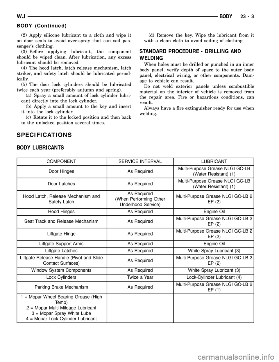
SPECIFICATIONS
BODY LUBRICANTS
COMPONENT SERVICE INTERVAL LUBRICANT
Door Hinges As RequiredMulti-Purpose Grease NLGI GC-LB
(Water Resistant) (1)
Door Latches As RequiredMulti-Purpose Grease NLGI GC-LB
(Water Resistant) (1)
Hood Latch, Release Mechanism and
Safety LatchAs Required
(When Performing Other
Underhood Service)Multi-Purpose Grease NLGI GC-LB 2
EP (2)
Hood Hinges As Required Engine Oil
Seat Track and Release Mechanism As RequiredMulti-Purpose Grease NLGI GC-LB 2
EP (2)
Liftgate Hinge As RequiredMulti-Purpose Grease NLGI GC-LB 2
EP (2)
Liftgate Support Arms As Required Engine Oil
Liftgate Latches As Required White Spray Lubricant (3)
Liftgate Release Handle (Pivot and Slide
Contact Surfaces)As RequiredMulti-Purpose Grease NLGI GC-LB 2
EP (2)
Window System Components As Required White Spray Lubricant (3)
Lock Cylinders Twice a Year Lock-Cylinder Lubricant (4)
Parking Brake Mechanism As RequiredMulti-Purpose Grease NLGI GC-LB 2
EP (1)
1 = Mopar Wheel Bearing Grease (High
Temp)
2 = Mopar Multi-Mileage Lubricant
3 = Mopar Spray White Lube
4 = Mopar Lock Cylinder Lubricant
WJBODY 23 - 3
BODY (Continued)