2002 JEEP GRAND CHEROKEE Bus
[x] Cancel search: BusPage 2096 of 2199

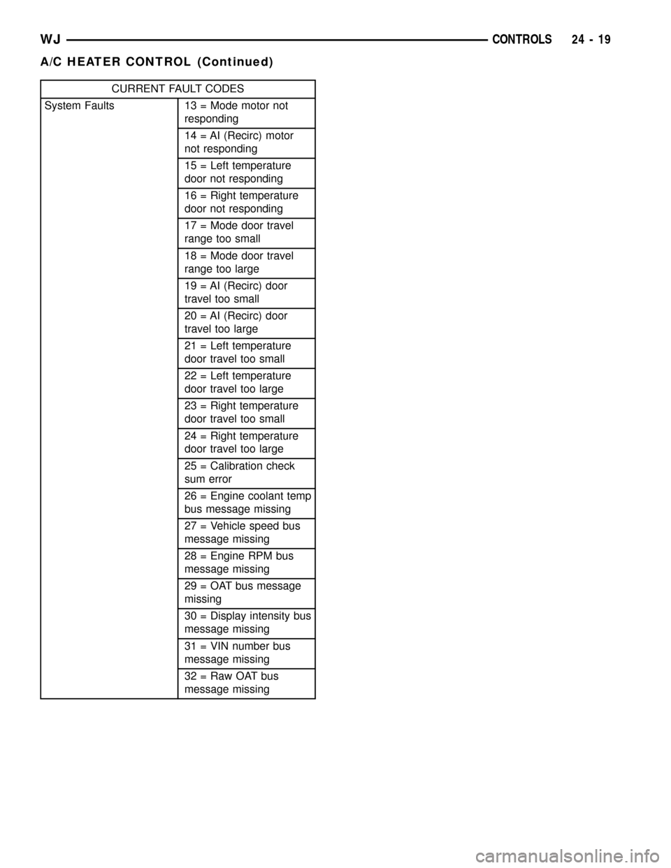
CURRENT FAULT CODES
System Faults 13 = Mode motor not
responding
14 = AI (Recirc) motor
not responding
15 = Left temperature
door not responding
16 = Right temperature
door not responding
17 = Mode door travel
range too small
18 = Mode door travel
range too large
19 = AI (Recirc) door
travel too small
20 = AI (Recirc) door
travel too large
21 = Left temperature
door travel too small
22 = Left temperature
door travel too large
23 = Right temperature
door travel too small
24 = Right temperature
door travel too large
25 = Calibration check
sum error
26 = Engine coolant temp
bus message missing
27 = Vehicle speed bus
message missing
28 = Engine RPM bus
message missing
29 = OAT bus message
missing
30 = Display intensity bus
message missing
31 = VIN number bus
message missing
32 = Raw OAT bus
message missing
WJCONTROLS 24 - 19
A/C HEATER CONTROL (Continued)
Page 2097 of 2199

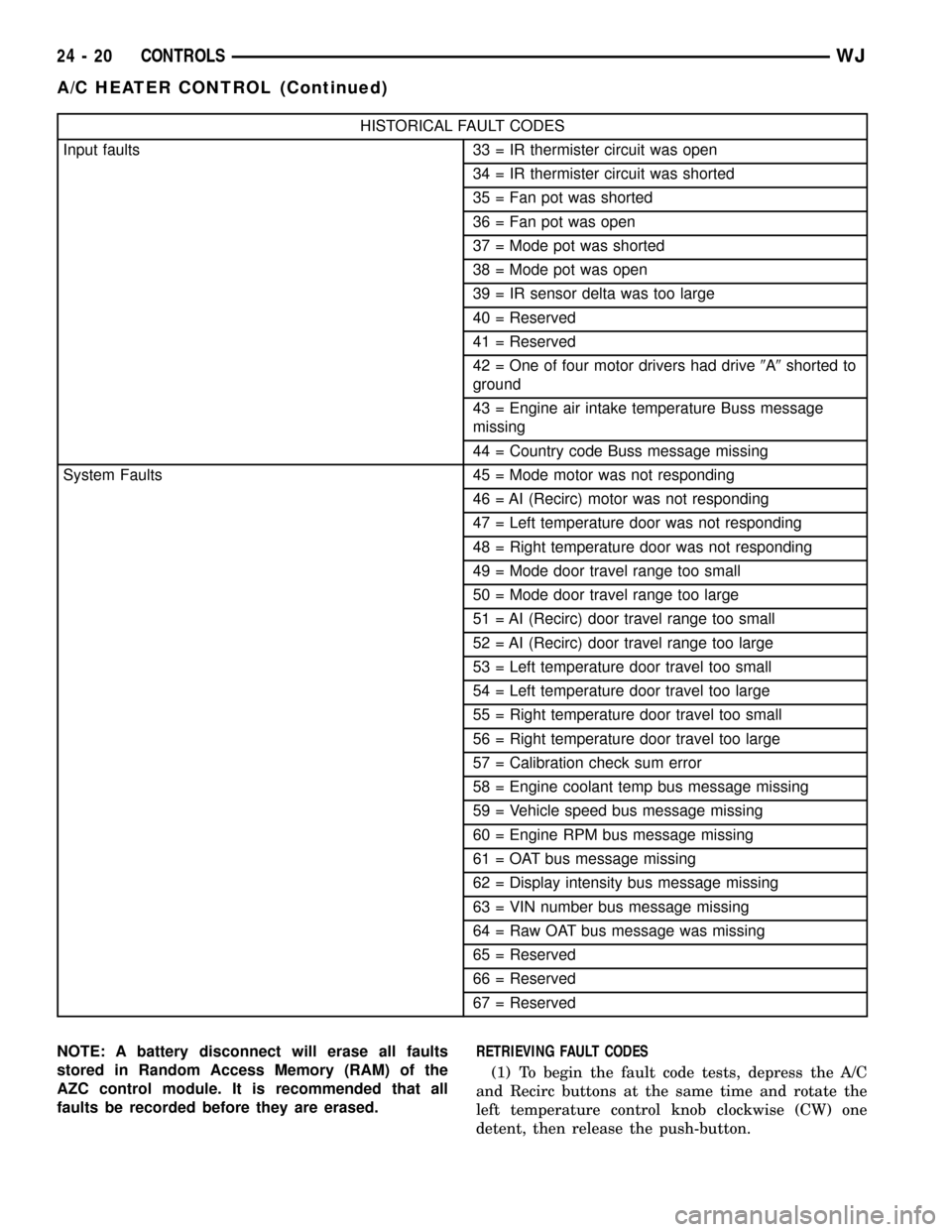
HISTORICAL FAULT CODES
Input faults 33 = IR thermister circuit was open
34 = IR thermister circuit was shorted
35 = Fan pot was shorted
36 = Fan pot was open
37 = Mode pot was shorted
38 = Mode pot was open
39 = IR sensor delta was too large
40 = Reserved
41 = Reserved
42 = One of four motor drivers had drive9A9shorted to
ground
43 = Engine air intake temperature Buss message
missing
44 = Country code Buss message missing
System Faults 45 = Mode motor was not responding
46 = AI (Recirc) motor was not responding
47 = Left temperature door was not responding
48 = Right temperature door was not responding
49 = Mode door travel range too small
50 = Mode door travel range too large
51 = AI (Recirc) door travel range too small
52 = AI (Recirc) door travel range too large
53 = Left temperature door travel too small
54 = Left temperature door travel too large
55 = Right temperature door travel too small
56 = Right temperature door travel too large
57 = Calibration check sum error
58 = Engine coolant temp bus message missing
59 = Vehicle speed bus message missing
60 = Engine RPM bus message missing
61 = OAT bus message missing
62 = Display intensity bus message missing
63 = VIN number bus message missing
64 = Raw OAT bus message was missing
65 = Reserved
66 = Reserved
67 = Reserved
NOTE: A battery disconnect will erase all faults
stored in Random Access Memory (RAM) of the
AZC control module. It is recommended that all
faults be recorded before they are erased.RETRIEVING FAULT CODES
(1) To begin the fault code tests, depress the A/C
and Recirc buttons at the same time and rotate the
left temperature control knob clockwise (CW) one
detent, then release the push-button.
24 - 20 CONTROLSWJ
A/C HEATER CONTROL (Continued)
Page 2122 of 2199

NOTE: The blend door sub-assembly is attached to
the housing with 2 screws, and may be removed for
service (Fig. 19).
ASSEMBLY
(1) Place the top half of the HVAC housing on the
bottom half. Be certain that each of the door pivot
pins align with the pivot holes in the HVAC housing.
(2) Install the 10 screws that secure the two hous-
ing halves to each other. Tighten the HVAC housing
screws to 2.2 N´m (20 in. lbs.).
(3) Attach the wire harness electrical connector(s)
to the mounts on the lower case at the blower motor
end of the unit.
(4) Install the 5 clips that secure the two housing
halves to each other. Check doors for binding after
replacement, and after assembly of housing.
(5) Install the screw with plastic washer holding
the lever assembly to the upper case section.
(6) Install the mode door actuator on the left side
of the housing.
INSTALLATION
WARNING: REVIEW THE WARNINGS AND CAU-
TIONS IN PLUMBING BEFORE PERFORMING THE
FOLLOWING OPERATION. (Refer to 24 - HEATING &
AIR CONDITIONING/PLUMBING - WARNING) (Refer
to 24 - HEATING & AIR CONDITIONING/PLUMBING -
CAUTION)Any kinks or sharp bends in the refrigerant plumb-
ing will reduce the capacity of the entire air condi-
tioning system. Kinks and sharp bends reduce the
flow of refrigerant in the system. A good rule for the
flexible hose refrigerant lines is to keep the radius of
all bends at least ten times the diameter of the hose.
In addition, the flexible hose refrigerant lines should
be routed so they are at least 80 millimeters (3
inches) from the exhaust manifold.
High pressures are produced in the refrigerant sys-
tem when the air conditioning compressor is operat-
ing. Extreme care must be exercised to make sure
that each of the refrigerant system connections is
pressure-tight and leak free. It is a good practice to
inspect all flexible hose refrigerant lines at least once
a year to make sure they are in good condition and
properly routed.
(1) Position the HVAC housing to the dash panel.
Be certain that the evaporator condensate drain tube
and the housing mounting studs are inserted into
their correct mounting holes.
(2) Install the HVAC housing mounting nuts to the
studs on the passenger compartment side of the dash
panel. Tighten the nuts to 4.5 N´m (40 in. lbs.).
(3) Connect the HVAC housing wire harness con-
nectors.
(4) Reinstall the rear floor heat ducts to the center
floor heat duct outlets.
(5) Install and tighten the nuts onto the HVAC
housing mounting studs on the engine compartment
side of the dash panel. Tighten the nuts to 7 N´m (60
in. lbs.).
(6) Reinstall the PCM to the passenger side dash
panel in the engine compartment. Refer to Electronic
Control Modules for the procedures.
(7) Reinstall the coolant reserve/overflow bottle to
the passenger side inner fender shield. Refer to Cool-
ing for the procedures.
(8) If the vehicle is equipped with the manual tem-
perature control system, connect the HVAC system
vacuum supply line connector to the tee fitting near
the heater core tubes.
(9) Unclamp/unplug the heater core hoses and
tubes. Connect the heater hoses to the heater core
tubes and fill the engine cooling system. Refer to
Cooling for the procedures.
(10) Unplug or remove the tape from the suction
line and the evaporator outlet tube fittings. Connect
the suction line to the evaporator outlet tube.
Tighten retaining nut to 28 N´m (250 in. lbs.).
(11) Unplug or remove the tape from the liquid
line and the evaporator inlet tube fittings. Connect
the liquid line to the evaporator inlet tube. Tighten
retaining nut to 28 N´m (250 in. lbs.).
(12) Evacuate the refrigerant system. (Refer to 24
- HEATING & AIR CONDITIONING/PLUMBING -
Fig. 19 BLEND DOOR SUB-ASSEMBLY (AZC)
1 - PASSENGER SIDE BLEND DOOR
2 - BLEND DOOR SUB-ASSEMBLY
3 - DOOR PIVOT SHAFT BUSHING
4 - DOOR SHAFT LEVER
5 - DRIVER SIDE BLEND DOOR
WJDISTRIBUTION 24 - 45
HVAC HOUSING (Continued)
Page 2123 of 2199

STANDARD PROCEDURE - REFRIGERANT SYS-
TEM EVACUATE)
(13) Charge the refrigerant system. (Refer to 24 -
HEATING & AIR CONDITIONING/PLUMBING -
STANDARD PROCEDURE - REFRIGERANT SYS-
TEM CHARGE)
(14) Install the instrument panel in the vehicle(Re-
fer to 23 - BODY/INSTRUMENT PANEL - INSTAL-
LATION).
(15) Connect the battery negative cable.
(16) Start the engine and check for proper opera-
tion of the heating and air conditioning systems.
BLEND DOOR
REMOVAL
WARNING: ON VEHICLES EQUIPPED WITH AIR-
BAGS, DISABLE THE AIRBAG SYSTEM BEFORE
ATTEMPTING ANY STEERING WHEEL, STEERING
COLUMN, OR INSTRUMENT PANEL COMPONENT
DIAGNOSIS OR SERVICE. DISCONNECT AND ISO-
LATE THE BATTERY NEGATIVE (GROUND) CABLE,
THEN WAIT TWO MINUTES FOR THE AIRBAG SYS-
TEM CAPACITOR TO DISCHARGE BEFORE PER-
FORMING FURTHER DIAGNOSIS OR SERVICE. THIS
IS THE ONLY SURE WAY TO DISABLE THE AIRBAG
SYSTEM. FAILURE TO TAKE THE PROPER PRE-
CAUTIONS COULD RESULT IN AN ACCIDENTAL
AIRBAG DEPLOYMENT AND POSSIBLE PERSONAL
INJURY.
(1) Remove and disassemble the HVAC housing.
(Refer to 24 - HEATING & AIR CONDITIONING/
DISTRIBUTION/HVAC HOUSING - REMOVAL)
(Refer to 24 - HEATING & AIR CONDITIONING/
DISTRIBUTION/HVAC HOUSING - DISASSEMBLY)
(2) Remove evaporator from lower case to ease
access to plastic door shaft bushing.
(3) Pinch the retention tabs holding the blend door
pivot shaft to the case. The 3 plastic tabs, located on
the inside of the case, are part of the shaft retainer.
(4) Remove door(s).
INSTALLATION
(1) Install the blend door(s) by snapping the pivot
shaft into the HVAC case.
(2) Install the evaporator in the lower case.
(3) Reassemble the HVAC housing and install in
the vehicle. (Refer to 24 - HEATING & AIR CONDI-
TIONING/DISTRIBUTION/HVAC HOUSING -
ASSEMBLY) (Refer to 24 - HEATING & AIR CON-
DITIONING/DISTRIBUTION/HVAC HOUSING -
INSTALLATION)NOTE: The blend door sub-assembly is attached to
the housing with 2 screws, and may be removed for
service (Fig. 20).
MODE DOOR
REMOVAL
REMOVAL - PANEL OUTLET DOOR
WARNING: ON VEHICLES EQUIPPED WITH AIR-
BAGS, DISABLE THE AIRBAG SYSTEM BEFORE
ATTEMPTING ANY STEERING WHEEL, STEERING
COLUMN, OR INSTRUMENT PANEL COMPONENT
DIAGNOSIS OR SERVICE. DISCONNECT AND ISO-
LATE THE BATTERY NEGATIVE (GROUND) CABLE,
THEN WAIT TWO MINUTES FOR THE AIRBAG SYS-
TEM CAPACITOR TO DISCHARGE BEFORE PER-
FORMING FURTHER DIAGNOSIS OR SERVICE. THIS
IS THE ONLY SURE WAY TO DISABLE THE AIRBAG
SYSTEM. FAILURE TO TAKE THE PROPER PRE-
CAUTIONS COULD RESULT IN AN ACCIDENTAL
AIRBAG DEPLOYMENT AND POSSIBLE PERSONAL
INJURY.
(1) Remove and disassemble the HVAC housing.
(Refer to 24 - HEATING & AIR CONDITIONING/
DISTRIBUTION/HVAC HOUSING - REMOVAL)
(Refer to 24 - HEATING & AIR CONDITIONING/
DISTRIBUTION/HVAC HOUSING - DISASSEMBLY)
Fig. 20 BLEND DOOR SUB-ASSEMBLY
1 - PASSENGER SIDE BLEND DOOR
2 - BLEND DOOR SUB-ASSEMBLY
3 - DOOR PIVOT SHAFT BUSHING
4 - DOOR SHAFT LEVER
5 - DRIVER SIDE BLEND DOOR
24 - 46 DISTRIBUTIONWJ
HVAC HOUSING (Continued)
Page 2129 of 2199

VISCOUS HEATER
DESCRIPTION
DESCRIPTION........................76
DESCRIPTION - VISCOUS HEATER
CLUTCH............................76
OPERATION
OPERATION - VISCOUS HEATER.........76
OPERATION - VISCOUS HEATER CLUTCH . . 76REMOVAL
REMOVAL - VISCOUS HEATER...........76
REMOVAL - VISCOUS HEATER CLUTCH . . . 76
INSTALLATION
INSTALLATION.......................78
INSTALLATION - VISCOUS HEATER
CLUTCH............................78
PLUMBING
DESCRIPTION - REFRIGERANT LINE
The refrigerant lines and hoses are used to carry
the refrigerant between the various air conditioning
system components. A barrier hose design with a
nylon tube, which is sandwiched between rubber lay-
ers, is used for the R-134a air conditioning system on
this vehicle. This nylon tube helps to further contain
the R-134a refrigerant, which has a smaller molecu-
lar structure than R-12 refrigerant. The ends of the
refrigerant hoses are made from lightweight alumi-
num or steel, and commonly use braze-less fittings.
Any kinks or sharp bends in the refrigerant plumb-
ing will reduce the capacity of the entire air condi-
tioning system. Kinks and sharp bends reduce the
flow of refrigerant in the system. A good rule for the
flexible hose refrigerant lines is to keep the radius of
all bends at least ten times the diameter of the hose.
In addition, the flexible hose refrigerant lines should
be routed so they are at least 80 millimeters (3
inches) from the exhaust manifold.
OPERATION - REFRIGERANT LINE
High pressures are produced in the refrigerant sys-
tem when the air conditioning compressor is operat-
ing. Extreme care must be exercised to make sure
that each of the refrigerant system connections is
pressure-tight and leak free. It is a good practice to
inspect all flexible hose refrigerant lines at least once
a year to make sure they are in good condition and
properly routed.
The refrigerant lines and hoses cannot be repaired
and, if faulty or damaged, they must be replaced.
WARNING
WARNING: THE AIR CONDITIONING SYSTEM CON-
TAINS REFRIGERANT UNDER HIGH PRESSURE.
SEVERE PERSONAL INJURY MAY RESULT FROM
IMPROPER SERVICE PROCEDURES. REPAIRS
SHOULD ONLY BE PERFORMED BY QUALIFIED
SERVICE PERSONNEL.
AVOID BREATHING THE REFRIGERANT AND
REFRIGERANT OIL VAPOR OR MIST. EXPOSURE
MAY IRRITATE THE EYES, NOSE, AND/OR THROAT.
WEAR EYE PROTECTION WHEN SERVICING THE
AIR CONDITIONING REFRIGERANT SYSTEM. SERI-
OUS EYE INJURY CAN RESULT FROM DIRECT
CONTACT WITH THE REFRIGERANT. IF EYE CON-
TACT OCCURS, SEEK MEDICAL ATTENTION IMME-
DIATELY.
DO NOT EXPOSE THE REFRIGERANT TO OPEN
FLAME. POISONOUS GAS IS CREATED WHEN
REFRIGERANT IS BURNED. AN ELECTRONIC LEAK
DETECTOR IS RECOMMENDED.
IF ACCIDENTAL SYSTEM DISCHARGE OCCURS,
VENTILATE THE WORK AREA BEFORE RESUMING
SERVICE. LARGE AMOUNTS OF REFRIGERANT
RELEASED IN A CLOSED WORK AREA WILL DIS-
PLACE THE OXYGEN AND CAUSE SUFFOCATION.
THE EVAPORATION RATE OF R-134a REFRIGER-
ANT AT AVERAGE TEMPERATURE AND ALTITUDE
IS EXTREMELY HIGH. AS A RESULT, ANYTHING
THAT COMES IN CONTACT WITH THE REFRIGER-
ANT WILL FREEZE. ALWAYS PROTECT THE SKIN
OR DELICATE OBJECTS FROM DIRECT CONTACT
WITH THE REFRIGERANT.
THE R-134a SERVICE EQUIPMENT OR THE VEHI-
CLE REFRIGERANT SYSTEM SHOULD NOT BE
PRESSURE TESTED OR LEAK TESTED WITH COM-
PRESSED AIR. SOME MIXTURES OF AIR AND
R-134a HAVE BEEN SHOWN TO BE COMBUSTIBLE
AT ELEVATED PRESSURES. THESE MIXTURES ARE
POTENTIALLY DANGEROUS, AND MAY RESULT IN
FIRE OR EXPLOSION CAUSING INJURY OR PROP-
ERTY DAMAGE.
24 - 52 PLUMBINGWJ
Page 2169 of 2199

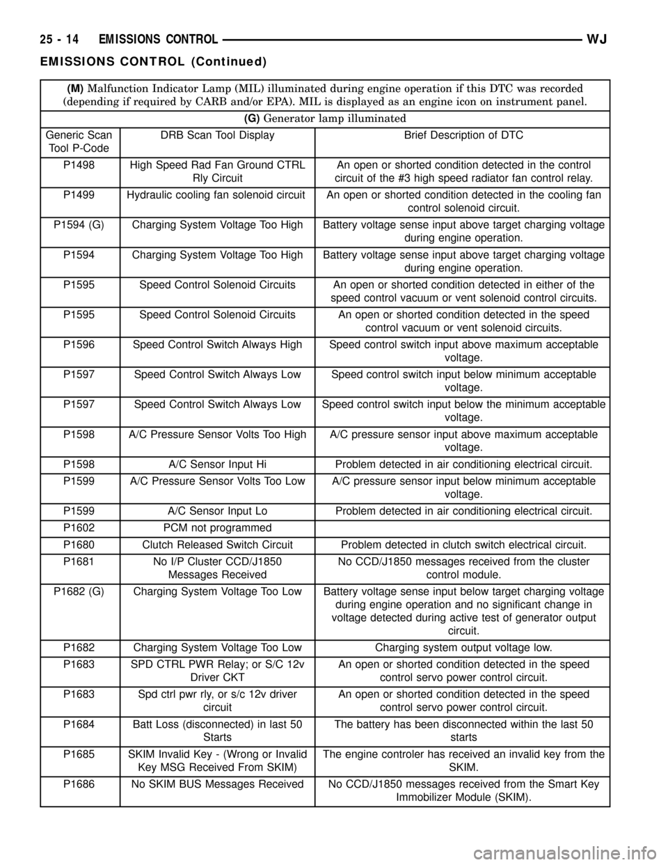
(M)Malfunction Indicator Lamp (MIL) illuminated during engine operation if this DTC was recorded
(depending if required by CARB and/or EPA). MIL is displayed as an engine icon on instrument panel.
(G)Generator lamp illuminated
Generic Scan
Tool P-CodeDRB Scan Tool Display Brief Description of DTC
P1498 High Speed Rad Fan Ground CTRL
Rly CircuitAn open or shorted condition detected in the control
circuit of the #3 high speed radiator fan control relay.
P1499 Hydraulic cooling fan solenoid circuit An open or shorted condition detected in the cooling fan
control solenoid circuit.
P1594 (G) Charging System Voltage Too High Battery voltage sense input above target charging voltage
during engine operation.
P1594 Charging System Voltage Too High Battery voltage sense input above target charging voltage
during engine operation.
P1595 Speed Control Solenoid Circuits An open or shorted condition detected in either of the
speed control vacuum or vent solenoid control circuits.
P1595 Speed Control Solenoid Circuits An open or shorted condition detected in the speed
control vacuum or vent solenoid circuits.
P1596 Speed Control Switch Always High Speed control switch input above maximum acceptable
voltage.
P1597 Speed Control Switch Always Low Speed control switch input below minimum acceptable
voltage.
P1597 Speed Control Switch Always Low Speed control switch input below the minimum acceptable
voltage.
P1598 A/C Pressure Sensor Volts Too High A/C pressure sensor input above maximum acceptable
voltage.
P1598 A/C Sensor Input Hi Problem detected in air conditioning electrical circuit.
P1599 A/C Pressure Sensor Volts Too Low A/C pressure sensor input below minimum acceptable
voltage.
P1599 A/C Sensor Input Lo Problem detected in air conditioning electrical circuit.
P1602 PCM not programmed
P1680 Clutch Released Switch Circuit Problem detected in clutch switch electrical circuit.
P1681 No I/P Cluster CCD/J1850
Messages ReceivedNo CCD/J1850 messages received from the cluster
control module.
P1682 (G) Charging System Voltage Too Low Battery voltage sense input below target charging voltage
during engine operation and no significant change in
voltage detected during active test of generator output
circuit.
P1682 Charging System Voltage Too Low Charging system output voltage low.
P1683 SPD CTRL PWR Relay; or S/C 12v
Driver CKTAn open or shorted condition detected in the speed
control servo power control circuit.
P1683 Spd ctrl pwr rly, or s/c 12v driver
circuitAn open or shorted condition detected in the speed
control servo power control circuit.
P1684 Batt Loss (disconnected) in last 50
StartsThe battery has been disconnected within the last 50
starts
P1685 SKIM Invalid Key - (Wrong or Invalid
Key MSG Received From SKIM)The engine controler has received an invalid key from the
SKIM.
P1686 No SKIM BUS Messages Received No CCD/J1850 messages received from the Smart Key
Immobilizer Module (SKIM).
25 - 14 EMISSIONS CONTROLWJ
EMISSIONS CONTROL (Continued)
Page 2170 of 2199

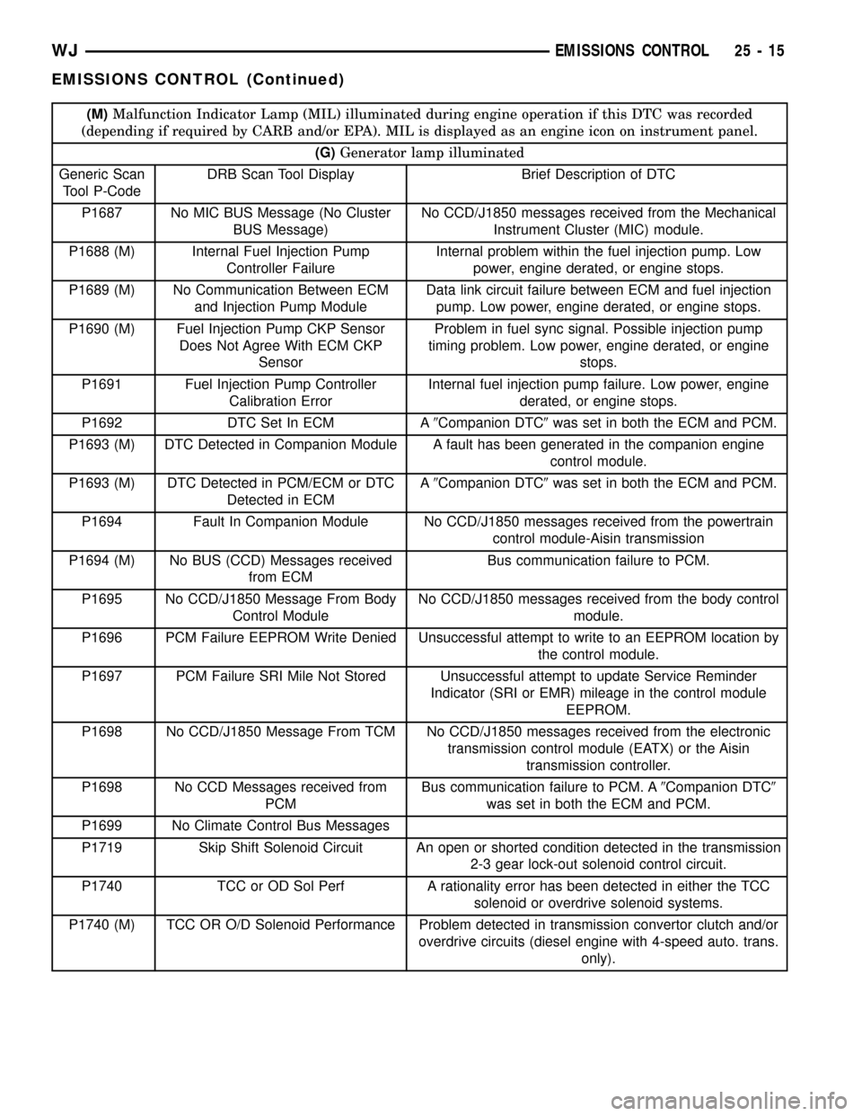
(M)Malfunction Indicator Lamp (MIL) illuminated during engine operation if this DTC was recorded
(depending if required by CARB and/or EPA). MIL is displayed as an engine icon on instrument panel.
(G)Generator lamp illuminated
Generic Scan
Tool P-CodeDRB Scan Tool Display Brief Description of DTC
P1687 No MIC BUS Message (No Cluster
BUS Message)No CCD/J1850 messages received from the Mechanical
Instrument Cluster (MIC) module.
P1688 (M) Internal Fuel Injection Pump
Controller FailureInternal problem within the fuel injection pump. Low
power, engine derated, or engine stops.
P1689 (M) No Communication Between ECM
and Injection Pump ModuleData link circuit failure between ECM and fuel injection
pump. Low power, engine derated, or engine stops.
P1690 (M) Fuel Injection Pump CKP Sensor
Does Not Agree With ECM CKP
SensorProblem in fuel sync signal. Possible injection pump
timing problem. Low power, engine derated, or engine
stops.
P1691 Fuel Injection Pump Controller
Calibration ErrorInternal fuel injection pump failure. Low power, engine
derated, or engine stops.
P1692 DTC Set In ECM A9Companion DTC9was set in both the ECM and PCM.
P1693 (M) DTC Detected in Companion Module A fault has been generated in the companion engine
control module.
P1693 (M) DTC Detected in PCM/ECM or DTC
Detected in ECMA9Companion DTC9was set in both the ECM and PCM.
P1694 Fault In Companion Module No CCD/J1850 messages received from the powertrain
control module-Aisin transmission
P1694 (M) No BUS (CCD) Messages received
from ECMBus communication failure to PCM.
P1695 No CCD/J1850 Message From Body
Control ModuleNo CCD/J1850 messages received from the body control
module.
P1696 PCM Failure EEPROM Write Denied Unsuccessful attempt to write to an EEPROM location by
the control module.
P1697 PCM Failure SRI Mile Not Stored Unsuccessful attempt to update Service Reminder
Indicator (SRI or EMR) mileage in the control module
EEPROM.
P1698 No CCD/J1850 Message From TCM No CCD/J1850 messages received from the electronic
transmission control module (EATX) or the Aisin
transmission controller.
P1698 No CCD Messages received from
PCMBus communication failure to PCM. A9Companion DTC9
was set in both the ECM and PCM.
P1699 No Climate Control Bus Messages
P1719 Skip Shift Solenoid Circuit An open or shorted condition detected in the transmission
2-3 gear lock-out solenoid control circuit.
P1740 TCC or OD Sol Perf A rationality error has been detected in either the TCC
solenoid or overdrive solenoid systems.
P1740 (M) TCC OR O/D Solenoid Performance Problem detected in transmission convertor clutch and/or
overdrive circuits (diesel engine with 4-speed auto. trans.
only).
WJEMISSIONS CONTROL 25 - 15
EMISSIONS CONTROL (Continued)
Page 2179 of 2199

EVAPORATIVE EMISSIONS
TABLE OF CONTENTS
page page
EVAPORATIVE EMISSIONS
DESCRIPTION
DESCRIPTION - EVAPORATION CONTROL
SYSTEM............................24
DESCRIPTION - CCV SYSTEM...........25
DESCRIPTION - PCV SYSTEM...........25
OPERATION
OPERATION - 4.0L CCV SYSTEM.........26
OPERATION - 4.7L PCV SYSTEM.........26
SPECIFICATIONS
TORQUE - EVAPORATION SYSTEM.......27
CCV HOSE
DIAGNOSIS AND TESTING - CCV SYSTEM -
4.0L................................28
REMOVAL - FIXED ORIFICE FITTING........28
INSTALLATION - FIXED ORIFICE FITTING....29
EVAP/PURGE SOLENOID
DESCRIPTION.........................29
OPERATION...........................29
REMOVAL.............................29
INSTALLATION.........................29
FUEL FILLER CAP
DESCRIPTION.........................29
OPERATION...........................29REMOVAL.............................29
LEAK DETECTION PUMP
DESCRIPTION.........................30
OPERATION...........................31
DIAGNOSIS AND TESTING - ENABLING
CONDITIONS TO RUN EVAP LEAK
DETECTION TEST.....................32
REMOVAL.............................35
INSTALLATION.........................35
ORVR
DESCRIPTION.........................37
OPERATION...........................37
P C V VA LV E
DIAGNOSIS AND TESTING - PCV VALVE/PCV
SYSTEM - 4.7L.......................37
REMOVAL - PCV VALVE - 4.7L.............39
INSTALLATION - PCV VALVE - 4.7L.........39
VACUUM LINES
DESCRIPTION.........................39
VAPOR CANISTER
DESCRIPTION.........................39
OPERATION...........................39
REMOVAL.............................40
INSTALLATION.........................40
EVAPORATIVE EMISSIONS
DESCRIPTION
DESCRIPTION - EVAPORATION CONTROL
SYSTEM
The evaporation control system prevents the emis-
sion of fuel tank vapors into the atmosphere. When
fuel evaporates in the fuel tank, the vapors pass
through the control valve, through the fuel manage-
ment valve, and through vent hoses and tubes to a
charcoal filled evaporative canister. The canister tem-
porarily holds the vapors. The Powertrain Control
Module (PCM) allows intake manifold vacuum todraw vapors into the combustion chambers during
certain operating conditions.
Gas powered engines use a duty cycle purge sys-
tem. The PCM controls vapor flow by operating the
duty cycle EVAP purge solenoid. Refer to Duty Cycle
EVAP Canister Purge Solenoid.
When equipped with certain emissions packages, a
Leak Detection Pump (LDP) will be used as part of
the evaporative system for OBD II requirements.
Also refer to Leak Detection Pump.
Vehicles powered with gasoline engines are also
equipped with ORVR (On-Board Refueling Vapor
Recovery). Refer to ORVR for additional information.
25 - 24 EVAPORATIVE EMISSIONSWJ