2002 JEEP GRAND CHEROKEE rings
[x] Cancel search: ringsPage 1844 of 2199
INPUT AND LOW RANGE GEARS
Inspect the low range gear pinions and pinion pins.
Replace the low range gear if any of the pins or pin-
ions are worn or damaged.
Inspect the thrust washers, retainer, and snap-
ring. Replace the snap-ring if bent, or distorted.
Replace the thrust washers and retainer if worn,
cracked or damaged in any way.
Examine the input gear carefully. Be sure the gear
teeth and bearing surfaces are in good condition.
Replace the gear if wear or damage is evident.
Check the input gear pilot bearing. Rotate the
bearing and check for roughness or noise. Also check
bearing position in the bore. The bearing should be
recessed approximately 2.5 mm (0.100 in.) below the
top edge of the bore. The bearing should not be
seated at the bottom of the bore. Replace the bearing
if worn, or roughness is evident. Replace both the
gear and bearing if the bearing is a loose fit in the
bore.
GEAR CASE AND RETAINERS
Examine both case halves and retainers carefully.
Replace any retainer or case half if wear, cracks, or
other damage is evident.
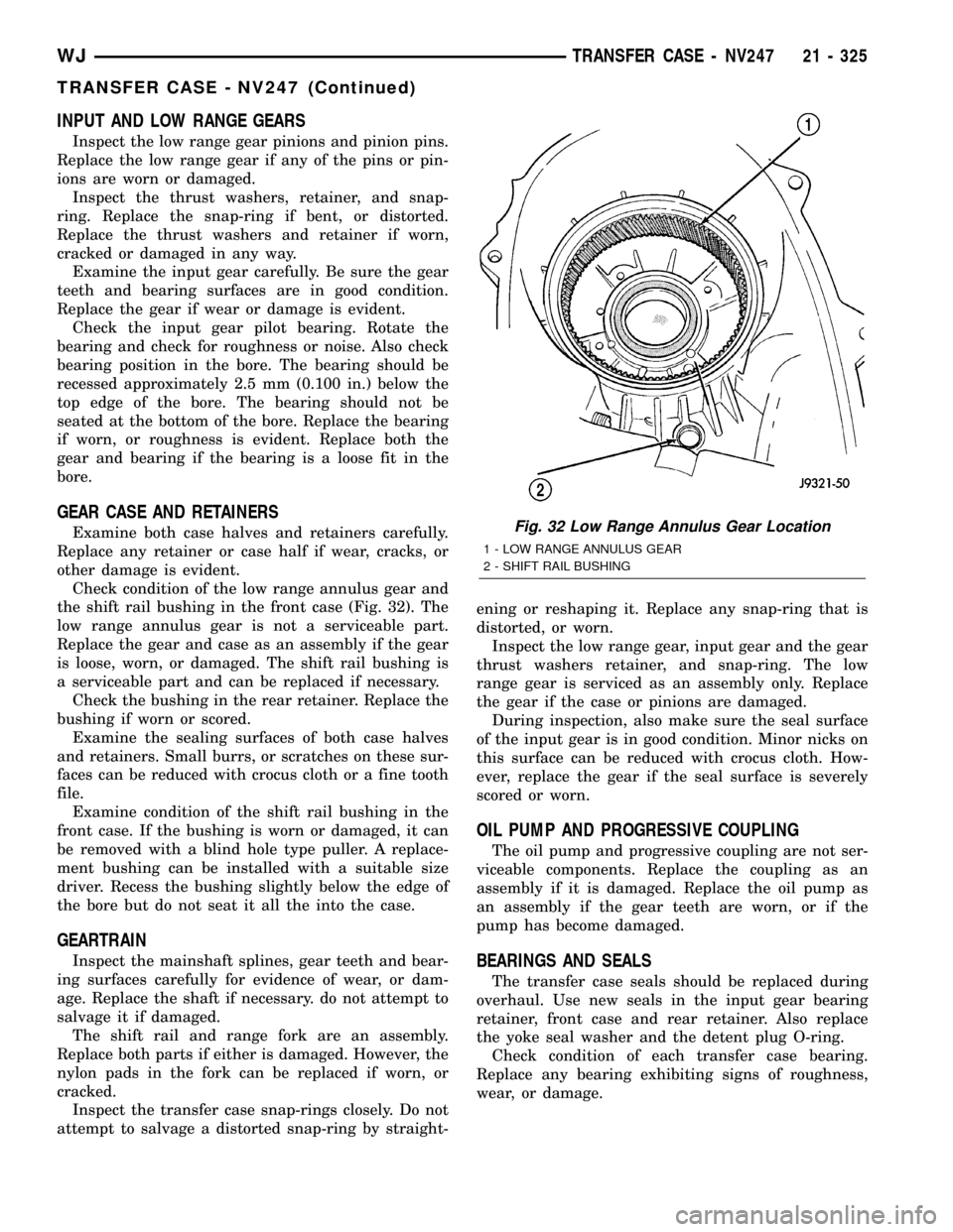
Check condition of the low range annulus gear and
the shift rail bushing in the front case (Fig. 32). The
low range annulus gear is not a serviceable part.
Replace the gear and case as an assembly if the gear
is loose, worn, or damaged. The shift rail bushing is
a serviceable part and can be replaced if necessary.
Check the bushing in the rear retainer. Replace the
bushing if worn or scored.
Examine the sealing surfaces of both case halves
and retainers. Small burrs, or scratches on these sur-
faces can be reduced with crocus cloth or a fine tooth
file.
Examine condition of the shift rail bushing in the
front case. If the bushing is worn or damaged, it can
be removed with a blind hole type puller. A replace-
ment bushing can be installed with a suitable size
driver. Recess the bushing slightly below the edge of
the bore but do not seat it all the into the case.
GEARTRAIN
Inspect the mainshaft splines, gear teeth and bear-
ing surfaces carefully for evidence of wear, or dam-
age. Replace the shaft if necessary. do not attempt to
salvage it if damaged.
The shift rail and range fork are an assembly.
Replace both parts if either is damaged. However, the
nylon pads in the fork can be replaced if worn, or
cracked.
Inspect the transfer case snap-rings closely. Do not
attempt to salvage a distorted snap-ring by straight-ening or reshaping it. Replace any snap-ring that is
distorted, or worn.
Inspect the low range gear, input gear and the gear
thrust washers retainer, and snap-ring. The low
range gear is serviced as an assembly only. Replace
the gear if the case or pinions are damaged.
During inspection, also make sure the seal surface
of the input gear is in good condition. Minor nicks on
this surface can be reduced with crocus cloth. How-
ever, replace the gear if the seal surface is severely
scored or worn.
OIL PUMP AND PROGRESSIVE COUPLING
The oil pump and progressive coupling are not ser-
viceable components. Replace the coupling as an
assembly if it is damaged. Replace the oil pump as
an assembly if the gear teeth are worn, or if the
pump has become damaged.
BEARINGS AND SEALS
The transfer case seals should be replaced during
overhaul. Use new seals in the input gear bearing
retainer, front case and rear retainer. Also replace
the yoke seal washer and the detent plug O-ring.
Check condition of each transfer case bearing.
Replace any bearing exhibiting signs of roughness,
wear, or damage.
Fig. 32 Low Range Annulus Gear Location
1 - LOW RANGE ANNULUS GEAR
2 - SHIFT RAIL BUSHING
WJTRANSFER CASE - NV247 21 - 325
TRANSFER CASE - NV247 (Continued)
Page 1845 of 2199
ASSEMBLY
Lubricate transfer case components with Mopart
Transfer Case Lubricant or petroleum jelly (where
indicated) during assembly.
CAUTION: The bearing bores in various transfer
case components contain oil feed holes. Make sure
replacement bearings do not block the holes.
BEARINGS AND SEALS
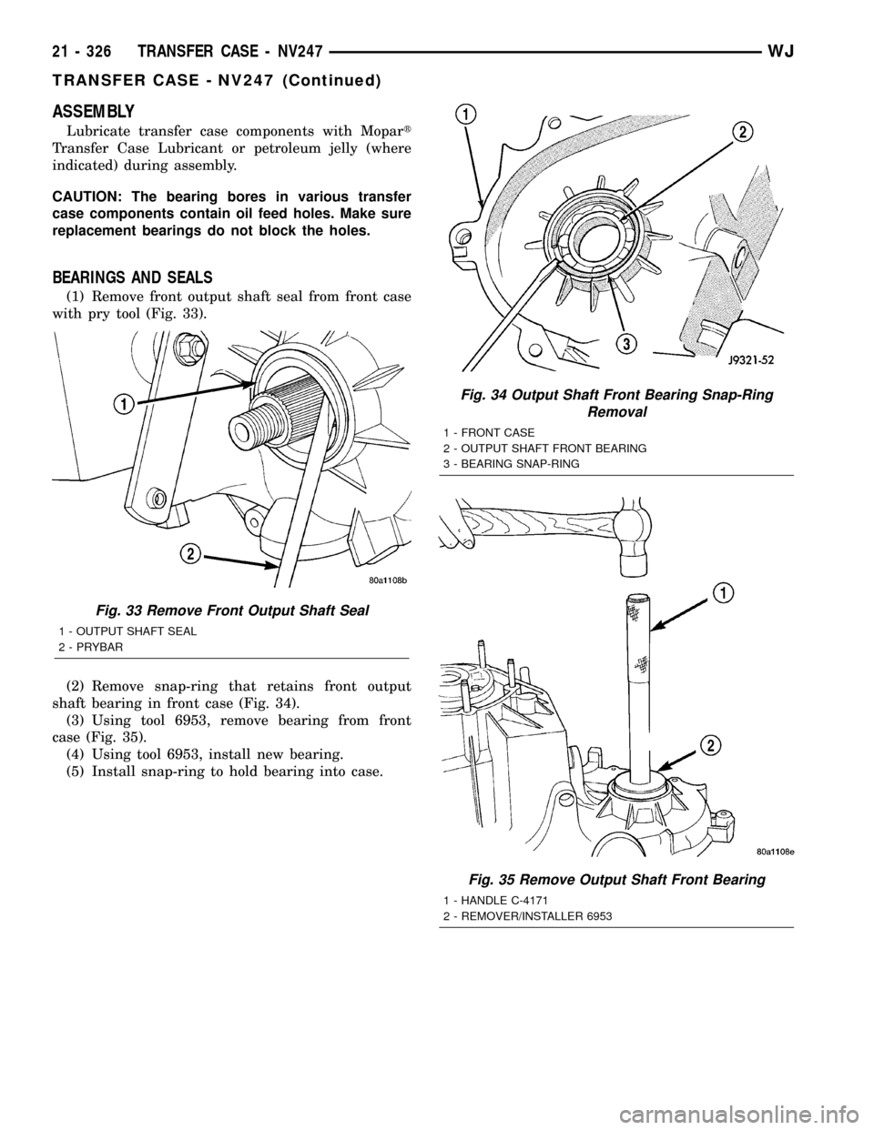
(1) Remove front output shaft seal from front case
with pry tool (Fig. 33).
(2) Remove snap-ring that retains front output
shaft bearing in front case (Fig. 34).
(3) Using tool 6953, remove bearing from front
case (Fig. 35).
(4) Using tool 6953, install new bearing.
(5) Install snap-ring to hold bearing into case.
Fig. 33 Remove Front Output Shaft Seal
1 - OUTPUT SHAFT SEAL
2 - PRYBAR
Fig. 34 Output Shaft Front Bearing Snap-Ring
Removal
1 - FRONT CASE
2 - OUTPUT SHAFT FRONT BEARING
3 - BEARING SNAP-RING
Fig. 35 Remove Output Shaft Front Bearing
1 - HANDLE C-4171
2 - REMOVER/INSTALLER 6953
21 - 326 TRANSFER CASE - NV247WJ
TRANSFER CASE - NV247 (Continued)
Page 1849 of 2199
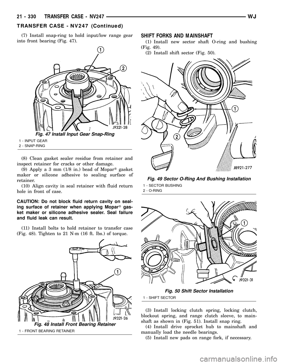
(7) Install snap-ring to hold input/low range gear
into front bearing (Fig. 47).
(8) Clean gasket sealer residue from retainer and
inspect retainer for cracks or other damage.
(9) Applya3mm(1/8 in.) bead of Mopartgasket
maker or silicone adhesive to sealing surface of
retainer.
(10) Align cavity in seal retainer with fluid return
hole in front of case.
CAUTION: Do not block fluid return cavity on seal-
ing surface of retainer when applying MoparTgas-
ket maker or silicone adhesive sealer. Seal failure
and fluid leak can result.
(11) Install bolts to hold retainer to transfer case
(Fig. 48). Tighten to 21 N´m (16 ft. lbs.) of torque.SHIFT FORKS AND MAINSHAFT
(1) Install new sector shaft O-ring and bushing
(Fig. 49).
(2) Install shift sector (Fig. 50).
(3) Install locking clutch spring, locking clutch,
blockout spring, and range clutch sleeve, to main-
shaft as shown in (Fig. 51). Install snap ring.
(4) Install drive sprocket hub to mainshaft and
manually load the needle bearings.
(5) Install new pads on range fork, if necessary.
Fig. 47 Install Input Gear Snap-Ring
1 - INPUT GEAR
2 - SNAP-RING
Fig. 48 Install Front Bearing Retainer
1 - FRONT BEARING RETAINER
Fig. 49 Sector O-Ring And Bushing Installation
1 - SECTOR BUSHING
2 - O-RING
Fig. 50 Shift Sector Installation
1 - SHIFT SECTOR
21 - 330 TRANSFER CASE - NV247WJ
TRANSFER CASE - NV247 (Continued)
Page 1851 of 2199
(6) Install roller bearings if removed.
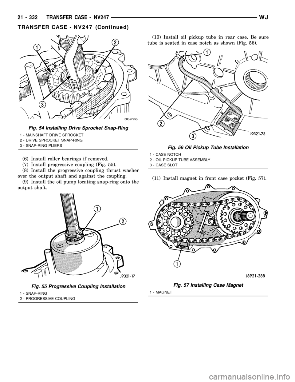
(7) Install progressive coupling (Fig. 55).
(8) Install the progressive coupling thrust washer
over the output shaft and against the coupling.
(9) Install the oil pump locating snap-ring onto the
output shaft.(10) Install oil pickup tube in rear case. Be sure
tube is seated in case notch as shown (Fig. 56).
(11) Install magnet in front case pocket (Fig. 57).
Fig. 54 Installing Drive Sprocket Snap-Ring
1 - MAINSHAFT DRIVE SPROCKET
2 - DRIVE SPROCKET SNAP-RING
3 - SNAP-RING PLIERS
Fig. 55 Progressive Coupling Installation
1 - SNAP-RING
2 - PROGRESSIVE COUPLING
Fig. 56 Oil Pickup Tube Installation
1 - CASE NOTCH
2 - OIL PICKUP TUBE ASSEMBLY
3 - CASE SLOT
Fig. 57 Installing Case Magnet
1 - MAGNET
21 - 332 TRANSFER CASE - NV247WJ
TRANSFER CASE - NV247 (Continued)
Page 1860 of 2199
TIRES/WHEELS
TABLE OF CONTENTS
page page
TIRES/WHEELS
DIAGNOSIS AND TESTING - TIRE AND
WHEEL RUNOUT......................1
STANDARD PROCEDURE
STANDARD PROCEDURE - TIRE AND
WHEEL BALANCE......................2
STANDARD PROCEDURE - MATCH
MOUNTING...........................4
STANDARD PROCEDURE - TIRE ROTATION . 5
STANDARD PROCEDURE - WHEEL
INSTALLATION........................5
TIRES
DESCRIPTION
DESCRIPTION - TIRES..................6
DESCRIPTION - RADIAL±PLY TIRES.......6
DESCRIPTION - TIRE INFLATION
PRESSURES..........................6
DESCRIPTION - TIRE PRESSURE FOR
HIGH SPEED..........................7
DESCRIPTION - REPLACEMENT TIRES.....7
DIAGNOSIS AND TESTING
DIAGNOSIS AND TESTING - PRESSURE
GAUGES.............................8
DIAGNOSIS AND TESTING - TREAD WEAR
INDICATORS..........................8
DIAGNOSIS AND TESTING - TIRE WEAR
PATTERNS...........................8
DIAGNOSIS AND TESTING - TIRE NOISE
OR VIBRATION........................8STANDARD PROCEDURE - REPAIRING
LEAKS...............................8
CLEANING.............................9
SPECIFICATIONS
TIRES...............................9
SPECIFICATIONS -.....................9
SPARE TIRE
DESCRIPTION - SPARE / TEMPORARY TIRE . . 10
WHEELS
DESCRIPTION.........................10
DIAGNOSIS AND TESTING - WHEEL
INSPECTION.........................10
STANDARD PROCEDURE - WHEEL
REPLACEMENT.......................10
SPECIFICATIONS
TORQUE CHART......................11
STUDS
REMOVAL.............................11
INSTALLATION.........................11
TIRE PRESSURE MONITORING
DESCRIPTION.........................12
OPERATION...........................12
DIAGNOSIS AND TESTING - TIRE PRESSURE
MONITORING SYSTEM.................12
SENSOR
REMOVAL - TIRE PRESSURE SENSOR/
TRANSMITTER.......................12
INSTALLATION - TIRE PRESSURE SENSOR/
TRANSMITTER.......................13
TIRES/WHEELS
DIAGNOSIS AND TESTING - TIRE AND WHEEL
RUNOUT
Radial runout is the difference between the high
and low points on the tire or wheel (Fig. 1).
Lateral runout is thewobbleof the tire or wheel.
Radial runout of more than 1.5 mm (.060 inch)
measured at the center line of the tread may cause
the vehicle to shake.
Lateral runout of more than 2.0 mm (.080 inch)
measured near the shoulder of the tire may cause the
vehicle to shake.
Sometimes radial runout can be reduced. Relocate
the wheel and tire assembly on the mounting studs
(See Method 1). If this does not reduce runout to an
acceptable level, the tire can be rotated on the wheel.
(See Method 2).
METHOD 1 (RELOCATE WHEEL ON HUB)
(1) Drive vehicle a short distance to eliminate tire
flat spotting from a parked position.
(2) Check wheel bearings and adjust if adjustable
or replace if necessary.
(3) Check the wheel mounting surface.
(4) Relocate wheel on the mounting, two studs
over from the original position.
(5) Tighten wheel nuts until all are properly
torqued, to eliminate brake distortion.
(6) Check radial runout. If still excessive, mark
tire sidewall, wheel, and stud at point of maximum
runout and proceed to Method 2.
METHOD 2 (RELOCATE TIRE ON WHEEL)
NOTE: Rotating the tire on wheel is particularly
effective when there is runout in both tire and
wheel.
WJTIRES/WHEELS 22 - 1
Page 1957 of 2199
FRONT HEADREST SLEEVE
REMOVAL
(1) Remove head restraint (Refer to 23 - BODY/
SEATS/FRONT HEADREST - REMOVAL).
(2) Remove seat back cover (Refer to 23 - BODY/
SEATS/FRONT SEAT BACK COVER - REMOVAL).
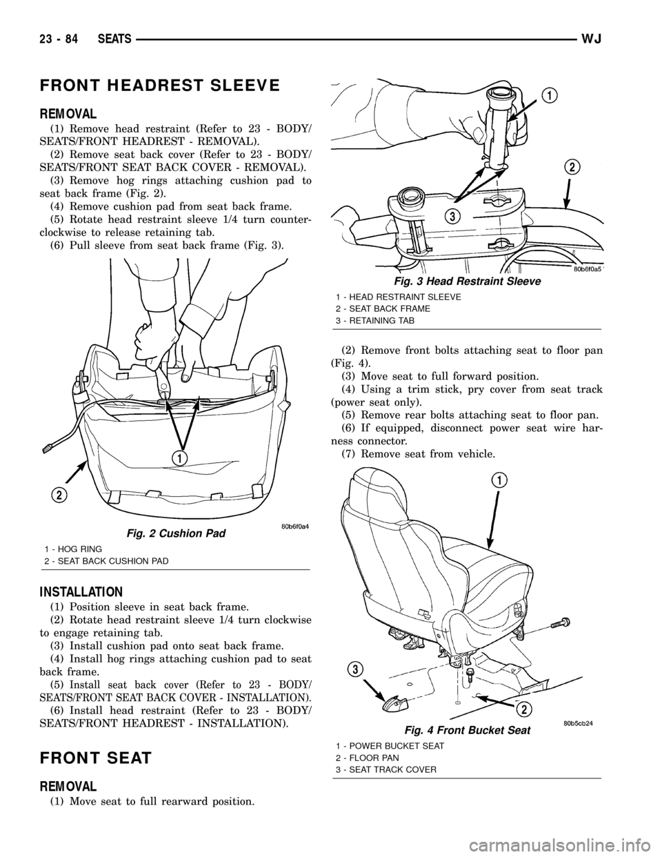
(3) Remove hog rings attaching cushion pad to
seat back frame (Fig. 2).
(4) Remove cushion pad from seat back frame.
(5) Rotate head restraint sleeve 1/4 turn counter-
clockwise to release retaining tab.
(6) Pull sleeve from seat back frame (Fig. 3).
INSTALLATION
(1) Position sleeve in seat back frame.
(2) Rotate head restraint sleeve 1/4 turn clockwise
to engage retaining tab.
(3) Install cushion pad onto seat back frame.
(4) Install hog rings attaching cushion pad to seat
back frame.
(5)
Install seat back cover (Refer to 23 - BODY/
SEATS/FRONT SEAT BACK COVER - INSTALLATION).
(6) Install head restraint (Refer to 23 - BODY/
SEATS/FRONT HEADREST - INSTALLATION).
FRONT SEAT
REMOVAL
(1) Move seat to full rearward position.(2) Remove front bolts attaching seat to floor pan
(Fig. 4).
(3) Move seat to full forward position.
(4) Using a trim stick, pry cover from seat track
(power seat only).
(5) Remove rear bolts attaching seat to floor pan.
(6) If equipped, disconnect power seat wire har-
ness connector.
(7) Remove seat from vehicle.
Fig. 2 Cushion Pad
1 - HOG RING
2 - SEAT BACK CUSHION PAD
Fig. 3 Head Restraint Sleeve
1 - HEAD RESTRAINT SLEEVE
2 - SEAT BACK FRAME
3 - RETAINING TAB
Fig. 4 Front Bucket Seat
1 - POWER BUCKET SEAT
2 - FLOOR PAN
3 - SEAT TRACK COVER
23 - 84 SEATSWJ
Page 1958 of 2199
INSTALLATION
(1) Position seat on floor pan.
(2) If equipped, connect power seat wire harness
connector.
(3) Install rear bolts attaching seat to floor pan.
Tighten bolts to 40 N´m (30 ft. lbs.) torque.
(4) If equipped, install cover on seat track.
(5) Move seat to full rearward position.
(6) Install front bolts attaching seat to floor pan.
Tighten bolts to 40 N´m (30 ft. lbs.) torque.
FRONT SEAT BACK
REMOVAL
(1) Move seat to full rearward position.
(2) Remove inboard bolt attaching seat back frame
to seat cushion frame.
(3) Move seat to full forward position.
(4) Move seat back to full recline position.
(5) Remove screws attaching seat side shield to
seat frame.
(6) Disconnect wire harness connector from
recliner motor, if equipped.
(7) From the underside of the seat, disconnect the
wire harness connector for the power lumber and/or
heated seat, if equipped.
(8) Remove outboard bolts attaching recliner to
seat cushion frame.
(9) Route the power lumber and/or heated seat
harness through the seat cushion cover, if equipped.
(10) Separate seat back from seat cushion.
INSTALLATION
(1) Position seat back on seat cushion.
(2) Route the power lumber and heater harness
through the seat cushion cover, if equipped.
(3) Install recliner bolts attaching seat back frame
to seat cushion frame. Tighten bolts to 28 N´m (20 ft.
lbs.) torque.
(4) Install the inboard bolt attaching seat back
frame to seat cushion frame. Tighten bolt to 47N´m
(35 ft.lbs.).
(5) Connect wire harness connector to recliner
motor and/or heated seat, if equipped.
(6) From the underside of the seat, connect the
power lumber and/or heated seat wire harness con-
nector to the seat harness, if equipped.
(7) Install screws attaching seat side shield to seat
frame.
FRONT SEAT BACK COVER
REMOVAL
(1) Remove head restraint (Refer to 23 - BODY/
SEATS/FRONT HEADREST - REMOVAL).
(2) Using a trim stick, carefully pry head restraint
release button caps from the top of seat back.
(3) Remove seat back (Refer to 23 - BODY/SEATS/
FRONT SEAT BACK - REMOVAL).
(4) Disengage J-strap at base of seat back.
(5) Slide hand between the face of the seat back
pad and the cushion cover and carefully separate
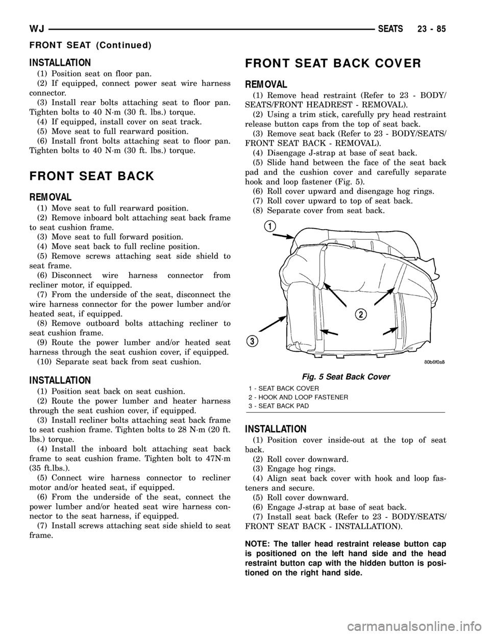
hook and loop fastener (Fig. 5).
(6) Roll cover upward and disengage hog rings.
(7) Roll cover upward to top of seat back.
(8) Separate cover from seat back.
INSTALLATION
(1) Position cover inside-out at the top of seat
back.
(2) Roll cover downward.
(3) Engage hog rings.
(4) Align seat back cover with hook and loop fas-
teners and secure.
(5) Roll cover downward.
(6) Engage J-strap at base of seat back.
(7) Install seat back (Refer to 23 - BODY/SEATS/
FRONT SEAT BACK - INSTALLATION).
NOTE: The taller head restraint release button cap
is positioned on the left hand side and the head
restraint button cap with the hidden button is posi-
tioned on the right hand side.
Fig. 5 Seat Back Cover
1 - SEAT BACK COVER
2 - HOOK AND LOOP FASTENER
3 - SEAT BACK PAD
WJSEATS 23 - 85
FRONT SEAT (Continued)
Page 1959 of 2199
(8) Position head restraint release button caps on
head restraint sleeves and press to secure.
(9) Install head restraint (Refer to 23 - BODY/
SEATS/FRONT HEADREST - INSTALLATION).
FRONT SEAT CUSHION/COVER
REMOVAL
(1) Remove seat from vehicle (Refer to 23 - BODY/
SEATS/FRONT SEAT - REMOVAL).
(2) Remove seat back (Refer to 23 - BODY/SEATS/
FRONT SEAT BACK - REMOVAL).
(3) Disengage J-straps attaching cushion cover to
seat cushion frame.
(4) Disengage hog rings attaching cushion cover to
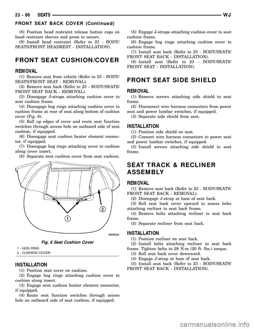
cushion frame at rear of seat along bottom of cushion
cover (Fig. 6).
(5) Roll up edges of cover and route seat function
switches through access hole on outboard side of seat
cushion, if equipped.
(6) Disengage seat cushion heater element connec-
tor, if equipped.
(7) Disengage hog rings attaching cover to cushion
along cover insert.
(8) Separate seat cushion cover from seat cushion.
INSTALLATION
(1) Position seat cover on cushion.
(2) Engage hog rings attaching cushion cover to
cushion along insert.
(3) Engage seat cushion heater element connector,
if equipped.
(4) Route seat function switches through access
hole on outboard side of seat cushion, if equipped.(5) Engage J-straps attaching cushion cover to seat
cushion frame.
(6) Engage hog rings attaching cushion cover to
cushion frame.
(7) Install seat back (Refer to 23 - BODY/SEATS/
FRONT SEAT BACK - INSTALLATION).
(8) Install seat (Refer to 23 - BODY/SEATS/
FRONT SEAT - INSTALLATION).
FRONT SEAT SIDE SHIELD
REMOVAL
(1) Remove screws attaching side shield to seat
frame.
(2) Disconnect wire harness connectors from power
seat and power lumbar switches, if equipped.
(3) Separate side shield from seat.
INSTALLATION
(1) Position side shield on seat.
(2) Connect wire harness connectors to power seat
and power lumbar switches, if equipped.
(3) Install screws attaching side shield to seat
frame.
SEAT TRACK & RECLINER
ASSEMBLY
REMOVAL
(1) Remove seat back (Refer to 23 - BODY/SEATS/
FRONT SEAT BACK - REMOVAL).
(2) Disengage J-strap at base of seat back.
(3) Roll seat back cover upward to access bolts
attaching recliner to seat back frame.
(4) Remove bolts attaching recliner to seat back
frame.
(5) Separate recliner from seat back.
INSTALLATION
(1) Position recliner on seat back.
(2) Install bolts attaching recliner to seat back
frame. Tighten bolts to 28 N´m (20 ft. lbs.) torque.
(3) Roll seat back cover downward.
(4) Engage J-strap at base of seat back.
(5) Install seat back (Refer to 23 - BODY/SEATS/
FRONT SEAT BACK - INSTALLATION).Fig. 6 Seat Cushion Cover
1 - HOG RING
2 - CUSHION COVER
23 - 86 SEATSWJ
FRONT SEAT BACK COVER (Continued)