2002 JEEP GRAND CHEROKEE weight
[x] Cancel search: weightPage 141 of 2199
(3) Remove the wheels and tires.
(4) Remove brake calipers and rotors.
(5) Disconnect parking brake cables from brackets
and lever.
(6) Remove wheel speed sensors.
(7) Remove brake hose at the axle junction block.
Do not disconnect the brake hydraulic lines at the
calipers.
(8) Disconnect the vent hose from the axle shaft
tube.
(9) Mark propeller shaft and yokes for installation
reference.
(10) Remove propeller shaft.
(11) Disconnect stabilizer bar links.
(12) Remove upper suspension arm rear axle ball
joint nut.
(13) Separate rear axle ball joint from the upper
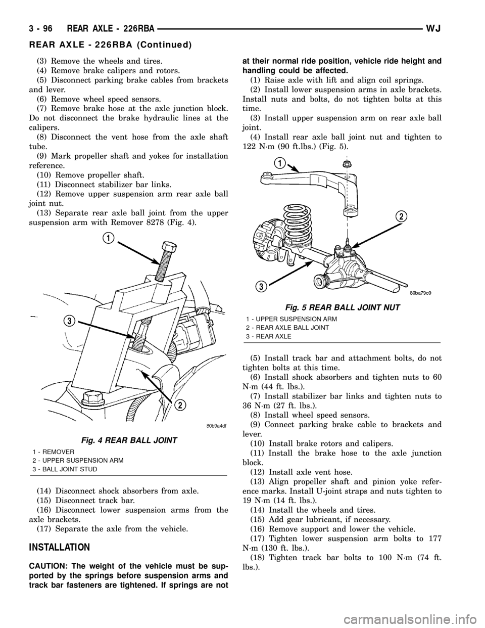
suspension arm with Remover 8278 (Fig. 4).
(14) Disconnect shock absorbers from axle.
(15) Disconnect track bar.
(16) Disconnect lower suspension arms from the
axle brackets.
(17) Separate the axle from the vehicle.
INSTALLATION
CAUTION: The weight of the vehicle must be sup-
ported by the springs before suspension arms and
track bar fasteners are tightened. If springs are notat their normal ride position, vehicle ride height and
handling could be affected.
(1) Raise axle with lift and align coil springs.
(2) Install lower suspension arms in axle brackets.
Install nuts and bolts, do not tighten bolts at this
time.
(3) Install upper suspension arm on rear axle ball
joint.
(4) Install rear axle ball joint nut and tighten to
122 N´m (90 ft.lbs.) (Fig. 5).
(5) Install track bar and attachment bolts, do not
tighten bolts at this time.
(6) Install shock absorbers and tighten nuts to 60
N´m (44 ft. lbs.).
(7) Install stabilizer bar links and tighten nuts to
36 N´m (27 ft. lbs.).
(8) Install wheel speed sensors.
(9) Connect parking brake cable to brackets and
lever.
(10) Install brake rotors and calipers.
(11) Install the brake hose to the axle junction
block.
(12) Install axle vent hose.
(13) Align propeller shaft and pinion yoke refer-
ence marks. Install U-joint straps and nuts tighten to
19 N´m (14 ft. lbs.).
(14) Install the wheels and tires.
(15) Add gear lubricant, if necessary.
(16) Remove support and lower the vehicle.
(17) Tighten lower suspension arm bolts to 177
N´m (130 ft. lbs.).
(18) Tighten track bar bolts to 100 N´m (74 ft.
lbs.).
Fig. 4 REAR BALL JOINT
1 - REMOVER
2 - UPPER SUSPENSION ARM
3 - BALL JOINT STUD
Fig. 5 REAR BALL JOINT NUT
1 - UPPER SUSPENSION ARM
2 - REAR AXLE BALL JOINT
3 - REAR AXLE
3 - 96 REAR AXLE - 226RBAWJ
REAR AXLE - 226RBA (Continued)
Page 187 of 2199
(8) Secure caliper to nearby suspension part with
wire.Do not allow brake hose to support caliper
weight.
(9) Remove the inboard brake shoe from the cali-
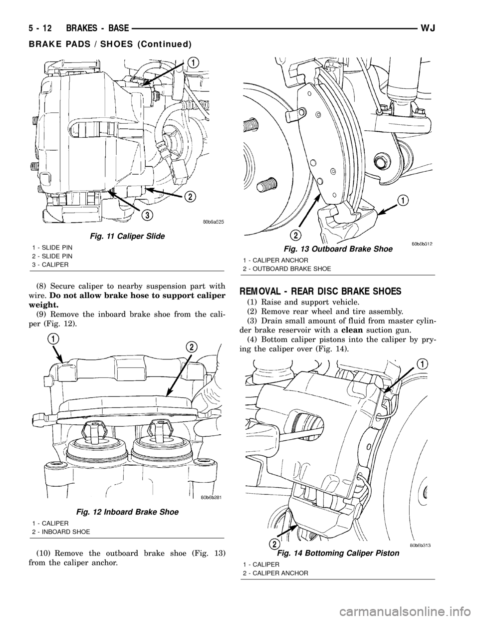
per (Fig. 12).
(10) Remove the outboard brake shoe (Fig. 13)
from the caliper anchor.REMOVAL - REAR DISC BRAKE SHOES
(1) Raise and support vehicle.
(2) Remove rear wheel and tire assembly.
(3) Drain small amount of fluid from master cylin-
der brake reservoir with acleansuction gun.
(4) Bottom caliper pistons into the caliper by pry-
ing the caliper over (Fig. 14).
Fig. 11 Caliper Slide
1 - SLIDE PIN
2 - SLIDE PIN
3 - CALIPER
Fig. 12 Inboard Brake Shoe
1 - CALIPER
2 - INBOARD SHOE
Fig. 13 Outboard Brake Shoe
1 - CALIPER ANCHOR
2 - OUTBOARD BRAKE SHOE
Fig. 14 Bottoming Caliper Piston
1 - CALIPER
2 - CALIPER ANCHOR
5 - 12 BRAKES - BASEWJ
BRAKE PADS / SHOES (Continued)
Page 188 of 2199
(5) Remove the caliper support spring by prying
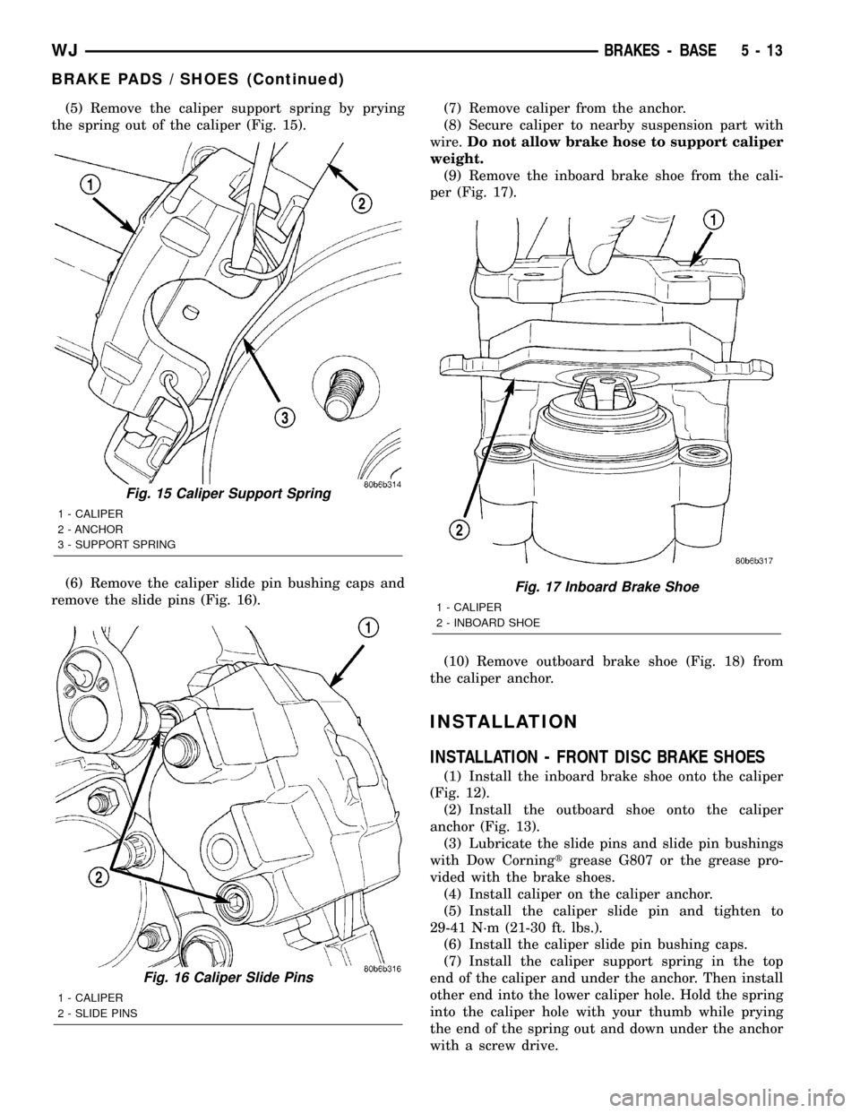
the spring out of the caliper (Fig. 15).
(6) Remove the caliper slide pin bushing caps and
remove the slide pins (Fig. 16).(7) Remove caliper from the anchor.
(8) Secure caliper to nearby suspension part with
wire.Do not allow brake hose to support caliper
weight.
(9) Remove the inboard brake shoe from the cali-
per (Fig. 17).
(10) Remove outboard brake shoe (Fig. 18) from
the caliper anchor.
INSTALLATION
INSTALLATION - FRONT DISC BRAKE SHOES
(1) Install the inboard brake shoe onto the caliper
(Fig. 12).
(2) Install the outboard shoe onto the caliper
anchor (Fig. 13).
(3) Lubricate the slide pins and slide pin bushings
with Dow Corningtgrease G807 or the grease pro-
vided with the brake shoes.
(4) Install caliper on the caliper anchor.
(5) Install the caliper slide pin and tighten to
29-41 N´m (21-30 ft. lbs.).
(6) Install the caliper slide pin bushing caps.
(7) Install the caliper support spring in the top
end of the caliper and under the anchor. Then install
other end into the lower caliper hole. Hold the spring
into the caliper hole with your thumb while prying
the end of the spring out and down under the anchor
with a screw drive.
Fig. 15 Caliper Support Spring
1 - CALIPER
2 - ANCHOR
3 - SUPPORT SPRING
Fig. 16 Caliper Slide Pins
1 - CALIPER
2 - SLIDE PINS
Fig. 17 Inboard Brake Shoe
1 - CALIPER
2 - INBOARD SHOE
WJBRAKES - BASE 5 - 13
BRAKE PADS / SHOES (Continued)
Page 208 of 2199
STANDARD PROCEDURE - DISC ROTOR
MACHINING
CAUTION: For vehicles equipped with the Quadra-
Drive System, consisting of the NV-247 transfer case
and a Vari-Lok differential in the front and rear axles,
the following steps must be done prior to the use of a
hub mounted on-vehicle brake lathe. Disconnect the
driveshaft (Refer to 3 - DIFFERENTIAL & DRIVELINE/
PROPELLER SHAFT/PROPELLER SHAFT - REMOVAL)
from the respective axle on which the brake rotors are
being machined. Temporarily remove both brake cali-
pers (Refer to 5 - BRAKES/HYDRAULIC/MECHANICAL/
DISC BRAKE CALIPERS - REMOVAL) from the axle
while disc rotor machining is in process. Both steps
will prevent unnecessary loads to the hub mounted
on-vehicle lathe and speed machining times. Install a
thread lock material to the driveshaft attaching bolts
when reinstalling (Refer to 3 - DIFFERENTIAL & DRIV-
ELINE/PROPELLER SHAFT/PROPELLER SHAFT -
INSTALLATION).
NOTE: A hub mounted on-vehicle lathe is recom-
mended. This type of lathe trues the rotor to the vehi-
cles hub/bearing.
The disc brake rotor can be machined if scored or
worn. The lathe must machine both sides of the rotor
simultaneously with dual cutter heads. The rotor
mounting surface must be clean before placing on the
lathe. Equipment capable of machining only one side at
a time may produce a tapered rotor.
CAUTION: Brake rotors that do not meet minimum
thickness specifications before or after machining
must be replaced.
REMOVAL
REMOVAL - FRONT DISC BRAKE ROTOR
NOTE: Front rotors and hub/bearings are matched
mounted for minimum lateral runout. Before removing
the rotor, mark the rotor and hub/bearing to maintain
original orientation.
(1) Raise and support the vehicle.
(2) Remove wheel and tire assembly.
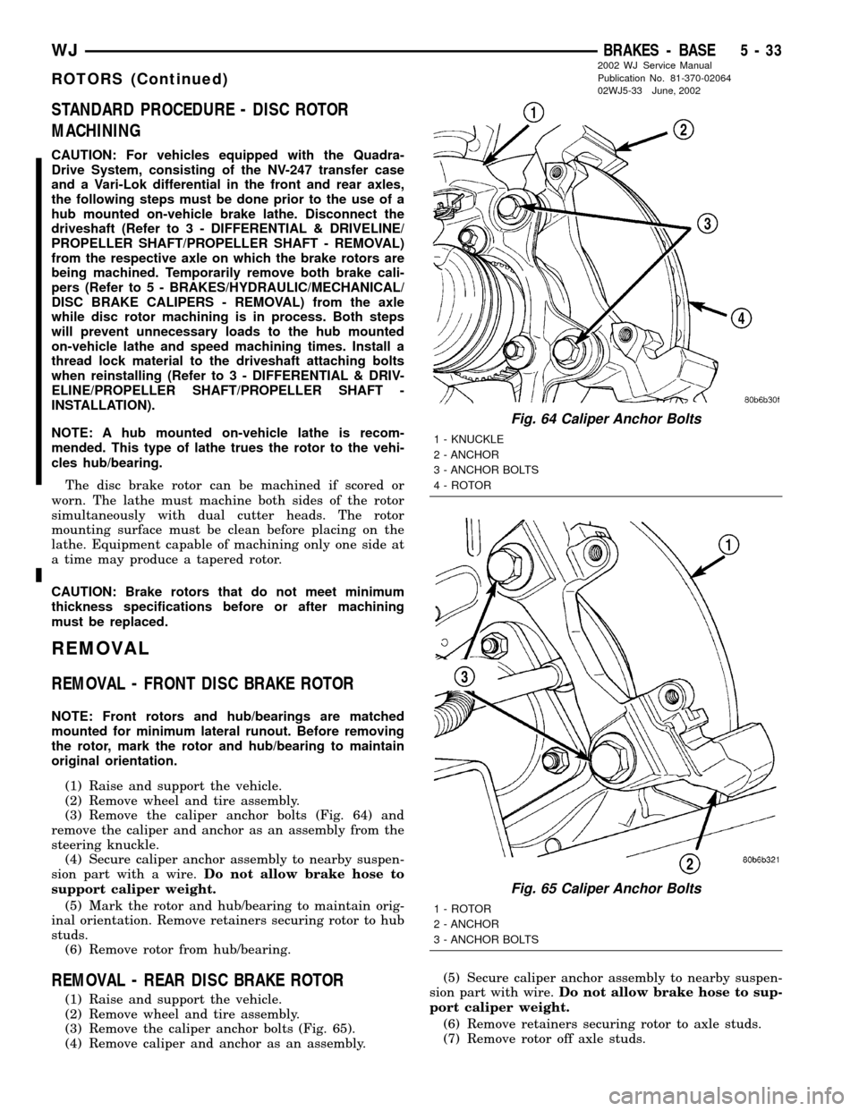
(3) Remove the caliper anchor bolts (Fig. 64) and
remove the caliper and anchor as an assembly from the
steering knuckle.
(4) Secure caliper anchor assembly to nearby suspen-
sion part with a wire.Do not allow brake hose to
support caliper weight.
(5) Mark the rotor and hub/bearing to maintain orig-
inal orientation. Remove retainers securing rotor to hub
studs.
(6) Remove rotor from hub/bearing.
REMOVAL - REAR DISC BRAKE ROTOR
(1) Raise and support the vehicle.
(2) Remove wheel and tire assembly.
(3) Remove the caliper anchor bolts (Fig. 65).
(4) Remove caliper and anchor as an assembly.(5) Secure caliper anchor assembly to nearby suspen-
sion part with wire.Do not allow brake hose to sup-
port caliper weight.
(6) Remove retainers securing rotor to axle studs.
(7) Remove rotor off axle studs.
Fig. 64 Caliper Anchor Bolts
1 - KNUCKLE
2 - ANCHOR
3 - ANCHOR BOLTS
4 - ROTOR
Fig. 65 Caliper Anchor Bolts
1 - ROTOR
2 - ANCHOR
3 - ANCHOR BOLTS
WJBRAKES - BASE 5 - 33
ROTORS (Continued)
2002 WJ Service Manual
Publication No. 81-370-02064
02WJ5-33 June, 2002
Page 366 of 2199

SPECIFICATIONS
TORQUE - STARTER
DESCRIPTION N-m Ft. Lbs. In. Lbs.
Stater Motor (B+) Terminal
(Diesel)27 20
Stater Motor (B+) Terminal
(Except Diesel)11.3 100
Starter Motor Retaining Bolts
(Diesel)27 20
Starter Motor Retaining Bolt
(Forward Facing 4.0L)41 30
Starter Motor Retaining Bolt
(Forward Facing 4.7L)54 40
Starter Motor Retaining Bolt
(Rearward Facing 4.7L)54 40
STARTER MOTOR - GAS POWERED
Starter Motor and Solenoid
Manufacturer Mitsubishi
Engine Application 4.0L/4.7L
Power Rating 1.4 Kilowatt (1.9 Horsepower)
Voltage12 Volts
Number of Fields 4
Number of Poles 4
Number of Brushes 4
Drive Type Planetary Gear Reduction
Free Running Test Voltage 11.2 Volts
Free Running Test Maximum Amperage Draw 90 Amperes
Free Running Test Minimum Speed 2400 rpm
Solenoid Closing Maximum Voltage Required 7.8 Volts
*Cranking Amperage Draw Test 160 Amperes
*Test at operating temperature. Cold engine, tight (new) engine, or heavy oil will increase starter amperage draw.
STARTER MOTOR
DESCRIPTION
The starter motors used for both the 4.0L and the
4.7L engines available in this model are very similar,
but are not interchangeable. Both starter motors are
mounted with two screws to the automatic transmis-
sion torque converter housing and are located on the
right side of the engine.
Each of these starter motors incorporates several
of the same features to create a reliable, efficient,compact, lightweight and powerful unit. The electric
motors of both starters feature four electromagnetic
field coils wound around four pole shoes, and four
brushes contact the motor commutator. Both starter
motors are rated at 1.4 kilowatts (about 1.9 horse-
power) output at 12 volts.
Both of these starter motors are serviced only as a
unit with their starter solenoids, and cannot be
repaired. If either component is faulty or damaged,
the entire starter motor and starter solenoid unit
must be replaced.
WJSTARTING 8F - 35
STARTING (Continued)
Page 467 of 2199

ness connector for the multi-function switch and the
instrument panel wire harness connector for the
BCM. There should be continuity. If OK, go to Step 3.
If not OK, repair the open headlamp switch mux cir-
cuit.
(3) Check for continuity between the headlamp
switch return circuit of the instrument panel wire
harness connector for the multi-function switch and a
good ground. There should be no continuity. If OK, go
to Step 4. If not OK, repair the shorted headlamp
switch return circuit.
(4) Check for continuity between the headlamp
switch return circuit of the instrument panel wire
harness connector for the multi-function switch and
the instrument panel wire harness connector for the
BCM. There should be continuity. If OK, use a
DRBIIItscan tool and the proper Diagnostic Proce-
dures manual to test the BCM. If not OK, repair the
open headlamp switch return circuit.
HEADLAMP UNIT
REMOVAL
(1) Remove the jack screw attaching the top of
headlamp to the headlamp mounting module (Fig.
14).
(2) Grasp upper inboard and lower outboard cor-
ners of headlamp (Fig. 15) and pull headlamp out-
ward.
(3) Remove all of the bulb sockets from headlamp
module.
(4) Separate the headlamp from vehicle.
INSTALLATION
CAUTION: Do not touch the bulb glass with fingers
or other oily surfaces. Reduced bulb life will result.
(1) Install all of the bulb sockets in headlamp mod-
ule.
(2) Position the headlamp on the vehicle and align
the ball studs with the sockets.
(3) Push the headlamp inward to secure the ball
studs with the sockets.
(4) Install the jack screw attaching the top of
headlamp to the headlamp mounting module.
ADJUSTMENTS
VEHICLE PREPARATION FOR LAMP ALIGNMENT
(1) Verify headlamp dimmer switch and high beam
indicator operation.
(2) Correct defective components that could hinder
proper lamp alignment.
(3) Verify proper tire inflation.
(4) Clean lamp lenses.
(5) Verify that luggage area is not heavily loaded.
(6) Fuel tank should be FULL. Add 2.94 kg (6.5
lbs.) of weight over the fuel tank for each estimated
gallon of missing fuel.
LAMP ALIGNMENT SCREEN PREPARATION
(1) Position vehicle on a level surface perpendicu-
lar to a flat wall 7.62 meters (25 ft) away from front
of headlamp lens (Fig. 16).
(2) If necessary, tape a line on the floor 7.62
meters (25 ft) away from and parallel to the wall.
(3) Measure from the floor up 1.27 meters (5 ft)
and tape a line on the wall at the centerline of the
vehicle. Sight along the centerline of the vehicle
Fig. 14 Headlamp Jackscrew
1 - JACKSCREW
2 - HEADLAMP
Fig. 15 Headlamp Removal
1 - HEADLAMP
8L - 16 LAMPS/LIGHTING - EXTERIORWJ
HEADLAMP SWITCH (Continued)
Page 1245 of 2199
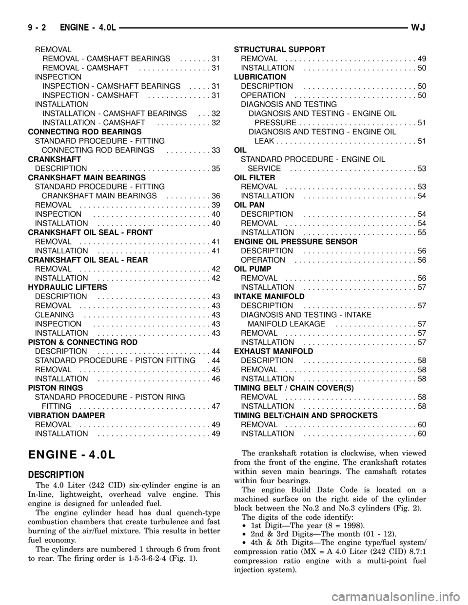
REMOVAL
REMOVAL - CAMSHAFT BEARINGS.......31
REMOVAL - CAMSHAFT................31
INSPECTION
INSPECTION - CAMSHAFT BEARINGS.....31
INSPECTION - CAMSHAFT..............31
INSTALLATION
INSTALLATION - CAMSHAFT BEARINGS . . . 32
INSTALLATION - CAMSHAFT............32
CONNECTING ROD BEARINGS
STANDARD PROCEDURE - FITTING
CONNECTING ROD BEARINGS..........33
CRANKSHAFT
DESCRIPTION.........................35
CRANKSHAFT MAIN BEARINGS
STANDARD PROCEDURE - FITTING
CRANKSHAFT MAIN BEARINGS..........36
REMOVAL.............................39
INSPECTION..........................40
INSTALLATION.........................40
CRANKSHAFT OIL SEAL - FRONT
REMOVAL.............................41
INSTALLATION.........................41
CRANKSHAFT OIL SEAL - REAR
REMOVAL.............................42
INSTALLATION.........................42
HYDRAULIC LIFTERS
DESCRIPTION.........................43
REMOVAL.............................43
CLEANING............................43
INSPECTION..........................43
INSTALLATION.........................43
PISTON & CONNECTING ROD
DESCRIPTION.........................44
STANDARD PROCEDURE - PISTON FITTING . 44
REMOVAL.............................45
INSTALLATION.........................46
PISTON RINGS
STANDARD PROCEDURE - PISTON RING
FITTING.............................47
VIBRATION DAMPER
REMOVAL.............................49
INSTALLATION.........................49STRUCTURAL SUPPORT
REMOVAL.............................49
INSTALLATION.........................50
LUBRICATION
DESCRIPTION.........................50
OPERATION...........................50
DIAGNOSIS AND TESTING
DIAGNOSIS AND TESTING - ENGINE OIL
PRESSURE..........................51
DIAGNOSIS AND TESTING - ENGINE OIL
LEAK...............................51
OIL
STANDARD PROCEDURE - ENGINE OIL
SERVICE............................53
OIL FILTER
REMOVAL.............................53
INSTALLATION.........................54
OIL PAN
DESCRIPTION.........................54
REMOVAL.............................54
INSTALLATION.........................55
ENGINE OIL PRESSURE SENSOR
DESCRIPTION.........................56
OPERATION...........................56
OIL PUMP
REMOVAL.............................56
INSTALLATION.........................57
INTAKE MANIFOLD
DESCRIPTION.........................57
DIAGNOSIS AND TESTING - INTAKE
MANIFOLD LEAKAGE..................57
REMOVAL.............................57
INSTALLATION.........................57
EXHAUST MANIFOLD
DESCRIPTION.........................58
REMOVAL.............................58
INSTALLATION.........................58
TIMING BELT / CHAIN COVER(S)
REMOVAL.............................58
INSTALLATION.........................58
TIMING BELT/CHAIN AND SPROCKETS
REMOVAL.............................60
INSTALLATION.........................60
ENGINE - 4.0L
DESCRIPTION
The 4.0 Liter (242 CID) six-cylinder engine is an
In-line, lightweight, overhead valve engine. This
engine is designed for unleaded fuel.
The engine cylinder head has dual quench-type
combustion chambers that create turbulence and fast
burning of the air/fuel mixture. This results in better
fuel economy.
The cylinders are numbered 1 through 6 from front
to rear. The firing order is 1-5-3-6-2-4 (Fig. 1).The crankshaft rotation is clockwise, when viewed
from the front of the engine. The crankshaft rotates
within seven main bearings. The camshaft rotates
within four bearings.
The engine Build Date Code is located on a
machined surface on the right side of the cylinder
block between the No.2 and No.3 cylinders (Fig. 2).
The digits of the code identify:
²1st DigitÐThe year (8 = 1998).
²2nd & 3rd DigitsÐThe month (01 - 12).
²4th & 5th DigitsÐThe engine type/fuel system/
compression ratio (MX = A 4.0 Liter (242 CID) 8.7:1
compression ratio engine with a multi-point fuel
injection system).
9 - 2 ENGINE - 4.0LWJ
Page 1258 of 2199
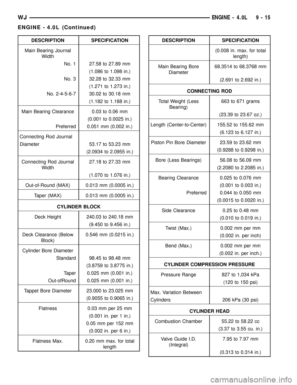
DESCRIPTION SPECIFICATION
Main Bearing Journal
Width
No. 1 27.58 to 27.89 mm
(1.086 to 1.098 in.)
No. 3 32.28 to 32.33 mm
(1.271 to 1.273 in.)
No. 2-4-5-6-7 30.02 to 30.18 mm
(1.182 to 1.188 in.)
Main Bearing Clearance 0.03 to 0.06 mm
(0.001 to 0.0025 in.)
Preferred 0.051 mm (0.002 in.)
Connecting Rod Journal
Diameter 53.17 to 53.23 mm
(2.0934 to 2.0955 in.)
Connecting Rod Journal
Width27.18 to 27.33 mm
(1.070 to 1.076 in.)
Out-of-Round (MAX) 0.013 mm (0.0005 in.)
Taper (MAX) 0.013 mm (0.0005 in.)
CYLINDER BLOCK
Deck Height 240.03 to 240.18 mm
(9.450 to 9.456 in.)
Deck Clearance (Below
Block)0.546 mm (0.0215 in.)
Cylinder Bore Diameter
Standard 98.45 to 98.48 mm
(3.8759 to 3.8775 in.)
Taper 0.025 mm (0.001 in.)
Out-ofRound 0.025 mm (0.001 in.)
Tappet Bore Diameter 23.000 to 23.025 mm
(0.9055 to 0.9065 in.)
Flatness 0.03 mm per 25 mm
(0.001 in. per 1 in.)
0.05 mm per 152 mm
(0.002 in. per 6 in.)
Flatness Max. 0.20 mm max. for total
lengthDESCRIPTION SPECIFICATION
(0.008 in. max. for total
length)
Main Bearing Bore
Diameter68.3514 to 68.3768 mm
(2.691 to 2.692 in.)
CONNECTING ROD
Total Weight (Less
Bearing)663 to 671 grams
(23.39 to 23.67 oz.)
Length (Center-to-Center) 155.52 to 155.62 mm
(6.123 to 6.127 in.)
Piston Pin Bore Diameter 23.59 to 23.62 mm
(0.9288 to 0.9298 in.)
Bore (Less Bearings) 56.08 to 56.09 mm
(2.2080 to 2.2085 in.)
Bearing Clearance 0.025 to 0.076 mm
(0.001 to 0.003 in.)
Preferred 0.044 to 0.050 mm
(0.0015 to 0.0020 in.)
Side Clearance 0.25 to 0.48 mm
(0.010 to 0.019 in.)
Twist (Max.) 0.002 mm per mm
(0.002 in. per inch)
Bend (Max.) 0.002 mm per mm
(0.002 in. per inch.)
CYLINDER COMPRESSION PRESSURE
Pressure Range 827 to 1,034 kPa
(120 to 150 psi)
Max. Variation Between
Cylinders 206 kPa (30 psi)
CYLINDER HEAD
Combustion Chamber 55.22 to 58.22 cc
(3.37 to 3.55 cu. in.)
Valve Guide I.D.
(Integral)7.95 to 7.97 mm
(0.313 to 0.314 in.)
WJENGINE - 4.0L 9 - 15
ENGINE - 4.0L (Continued)