2002 JEEP GRAND CHEROKEE track bar
[x] Cancel search: track barPage 525 of 2199

ing switch unit removal and installation, while both
knobs for the ten-way power seat switch unit must
be removed.
The individual switches in both power seat switch
units cannot be repaired. If one switch is damaged or
faulty, the entire power seat switch unit must be
replaced.
OPERATION
The power seat tracks of both the six-way and the
ten-way power seat systems can be adjusted in six
different ways using the power seat switches. The
ten-way system has the additional power seat
recliner switch integral to the power seat switch and
also has a separate, stand-alone switch to control the
power lumbar adjuster. See the owner's manual in
the vehicle glove box for more information on the
power seat switch functions and the seat adjusting
procedures.
When a power switch control knob or knobs are
actuated, a battery feed and a ground path are
applied through the switch contacts to the power seat
track or recliner adjuster motor. The selected
adjuster motor operates to move the seat track or
recliner through its drive unit in the selected direc-
tion until the switch is released, or until the travel
limit of the adjuster is reached. When the switch is
moved in the opposite direction, the battery feed and
ground path to the motor are reversed through the
switch contacts. This causes the adjuster motor to
run in the opposite direction.
No power seat switch should be held applied in any
direction after the adjuster has reached its travel
limit. The power seat adjuster motors each contain a
self-resetting circuit breaker to protect them fromoverload. However, consecutive or frequent resetting
of the circuit breaker must not be allowed to con-
tinue, or the motor may be damaged.
DIAGNOSIS AND TESTING - PASSENGER SEAT
SWITCH
For complete circuit diagrams, refer toWiring
Diagrams.
(1) Disconnect and isolate the battery negative
cable.
(2) Remove the power seat switch from the out-
board seat cushion side shield. Refer to the procedure
in this section of the manual.
(3) Use an ohmmeter to test the continuity of the
power seat switch in each switch position. See the
Power Seat Switch Continuity chart (Fig. 15) or (Fig.
16). If OK, refer toDiagnosis and Testing Power
Seat TrackorDiagnosis and Testing Power Seat
Reclinerin this section. If not OK, replace the
faulty power seat switch.
Fig. 14 Ten-Way Power Seat Switches - Typical
1 - OUTBOARD CUSHION SIDE SHIELD
2 - POWER SEAT RECLINER SWITCH
3 - POWER SEAT TRACK SWITCH
4 - POWER LUMBAR SWITCH
Fig. 15 Rear Of Six-Way Power Seat Switch
SIX-WAY POWER SEAT SWITCH TEST
LEFT SWITCH
POSITIONRIGHT
SWITCH
POSITIONCONTINUITY
BETWEEN
OFF OFFB-N, B-J, B-M,
B-E, B-L, B-K
VERTICAL UPVERTICAL
DOWNA-J, A-N, B-M,
B-E
VERTICAL
DOWNVERTICAL UPA-E, A-M, B-N,
B-J
HORIZONTAL
FORWARDHORIZONTAL
REARWARDA-K, B-L
FRONT TILT
UPFRONT TILT
DOWNA-J, B-E
FRONT TILT
DOWNFRONT TILT
UPA-E, B-J
REAR TILT UPREAR TILT
DOWNA-N, B-M
REAR TILT
DOWNREAR TILT UP A-M, B-N
8N - 28 POWER SEAT SYSTEMWJ
PASSENGER SEAT SWITCH (Continued)
Page 1479 of 2199
DIAGNOSIS AND TESTING
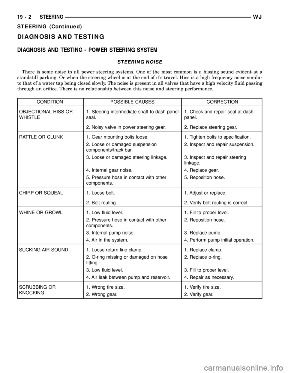
DIAGNOSIS AND TESTING - POWER STEERING SYSTEM
STEERING NOISE
There is some noise in all power steering systems. One of the most common is a hissing sound evident at a
standstill parking. Or when the steering wheel is at the end of it's travel. Hiss is a high frequency noise similar
to that of a water tap being closed slowly. The noise is present in all valves that have a high velocity fluid passing
through an orifice. There is no relationship between this noise and steering performance.
CONDITION POSSIBLE CAUSES CORRECTION
OBJECTIONAL HISS OR
WHISTLE1. Steering intermediate shaft to dash panel
seal.1. Check and repair seal at dash
panel.
2. Noisy valve in power steering gear. 2. Replace steering gear.
RATTLE OR CLUNK 1. Gear mounting bolts loose. 1. Tighten bolts to specification.
2. Loose or damaged suspension
components/track bar.2. Inspect and repair suspension.
3. Loose or damaged steering linkage. 3. Inspect and repair steering
linkage.
4. Internal gear noise. 4. Replace gear.
5. Pressure hose in contact with other
components.5. Reposition hose.
CHIRP OR SQUEAL 1. Loose belt. 1. Adjust or replace.
2. Belt routing. 2. Verify belt routing is correct.
WHINE OR GROWL 1. Low fluid level. 1. Fill to proper level.
2. Pressure hose in contact with other
components.2. Reposition hose.
3. Internal pump noise. 3. Replace pump.
4. Air in the system. 4. Perform pump initial operation.
SUCKING AIR SOUND 1. Loose return line clamp. 1. Replace clamp.
2. O-ring missing or damaged on hose
fitting.2. Replace o-ring.
3. Low fluid level. 3. Fill to proper level.
4. Air leak between pump and reservoir. 4. Repair as necessary.
SCRUBBING OR
KNOCKING1. Wrong tire size. 1. Verify tire size.
2. Wrong gear. 2. Verify gear.
19 - 2 STEERINGWJ
STEERING (Continued)
Page 1959 of 2199
(8) Position head restraint release button caps on
head restraint sleeves and press to secure.
(9) Install head restraint (Refer to 23 - BODY/
SEATS/FRONT HEADREST - INSTALLATION).
FRONT SEAT CUSHION/COVER
REMOVAL
(1) Remove seat from vehicle (Refer to 23 - BODY/
SEATS/FRONT SEAT - REMOVAL).
(2) Remove seat back (Refer to 23 - BODY/SEATS/
FRONT SEAT BACK - REMOVAL).
(3) Disengage J-straps attaching cushion cover to
seat cushion frame.
(4) Disengage hog rings attaching cushion cover to
cushion frame at rear of seat along bottom of cushion
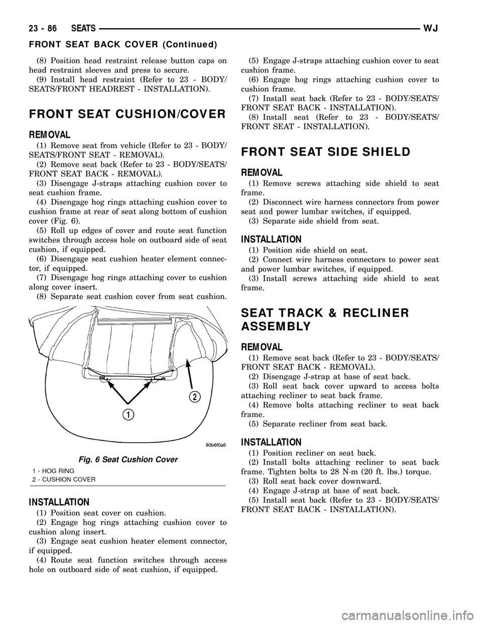
cover (Fig. 6).
(5) Roll up edges of cover and route seat function
switches through access hole on outboard side of seat
cushion, if equipped.
(6) Disengage seat cushion heater element connec-
tor, if equipped.
(7) Disengage hog rings attaching cover to cushion
along cover insert.
(8) Separate seat cushion cover from seat cushion.
INSTALLATION
(1) Position seat cover on cushion.
(2) Engage hog rings attaching cushion cover to
cushion along insert.
(3) Engage seat cushion heater element connector,
if equipped.
(4) Route seat function switches through access
hole on outboard side of seat cushion, if equipped.(5) Engage J-straps attaching cushion cover to seat
cushion frame.
(6) Engage hog rings attaching cushion cover to
cushion frame.
(7) Install seat back (Refer to 23 - BODY/SEATS/
FRONT SEAT BACK - INSTALLATION).
(8) Install seat (Refer to 23 - BODY/SEATS/
FRONT SEAT - INSTALLATION).
FRONT SEAT SIDE SHIELD
REMOVAL
(1) Remove screws attaching side shield to seat
frame.
(2) Disconnect wire harness connectors from power
seat and power lumbar switches, if equipped.
(3) Separate side shield from seat.
INSTALLATION
(1) Position side shield on seat.
(2) Connect wire harness connectors to power seat
and power lumbar switches, if equipped.
(3) Install screws attaching side shield to seat
frame.
SEAT TRACK & RECLINER
ASSEMBLY
REMOVAL
(1) Remove seat back (Refer to 23 - BODY/SEATS/
FRONT SEAT BACK - REMOVAL).
(2) Disengage J-strap at base of seat back.
(3) Roll seat back cover upward to access bolts
attaching recliner to seat back frame.
(4) Remove bolts attaching recliner to seat back
frame.
(5) Separate recliner from seat back.
INSTALLATION
(1) Position recliner on seat back.
(2) Install bolts attaching recliner to seat back
frame. Tighten bolts to 28 N´m (20 ft. lbs.) torque.
(3) Roll seat back cover downward.
(4) Engage J-strap at base of seat back.
(5) Install seat back (Refer to 23 - BODY/SEATS/
FRONT SEAT BACK - INSTALLATION).Fig. 6 Seat Cushion Cover
1 - HOG RING
2 - CUSHION COVER
23 - 86 SEATSWJ
FRONT SEAT BACK COVER (Continued)
Page 1960 of 2199
SEAT TRACK ADJUSTER
REMOVAL
(1) Remove seat (Refer to 23 - BODY/SEATS/
FRONT SEAT - REMOVAL).
(2) Remove side shield (Refer to 23 - BODY/
SEATS/FRONT SEAT SIDE SHIELD - REMOVAL).
(3) Remove nuts attaching seat track adjuster to
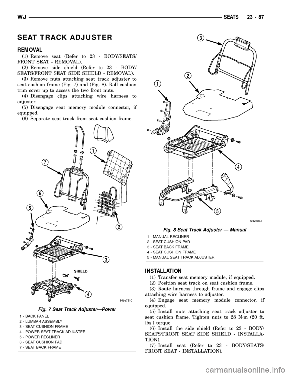
seat cushion frame (Fig. 7) and (Fig. 8). Roll cushion
trim cover up to access the two front nuts.
(4) Disengage clips attaching wire harness to
adjuster.
(5) Disengage seat memory module connector, if
equipped.
(6) Separate seat track from seat cushion frame.
INSTALLATION
(1) Transfer seat memory module, if equipped.
(2) Position seat track on seat cushion frame.
(3) Route harness through frame and engage clips
attaching wire harness to adjuster.
(4) Engage seat memory module connector, if
equipped.
(5) Install nuts attaching seat track adjuster to
seat cushion frame. Tighten nuts to 28 N´m (20 ft.
lbs.) torque.
(6) Install the side shield (Refer to 23 - BODY/
SEATS/FRONT SEAT SIDE SHIELD - INSTALLA-
TION).
(7) Install seat (Refer to 23 - BODY/SEATS/
FRONT SEAT - INSTALLATION).
Fig. 7 Seat Track AdjusterÐPower
1 - BACK PANEL
2 - LUMBAR ASSEMBLY
3 - SEAT CUSHION FRAME
4 - POWER SEAT TRACK ADJUSTER
5 - POWER RECLINER
6 - SEAT CUSHION PAD
7 - SEAT BACK FRAME
Fig. 8 Seat Track Adjuster Ð Manual
1 - MANUAL RECLINER
2 - SEAT CUSHION PAD
3 - SEAT BACK FRAME
4 - SEAT CUSHION FRAME
5 - MANUAL SEAT TRACK ADJUSTER
WJSEATS 23 - 87
Page 2026 of 2199
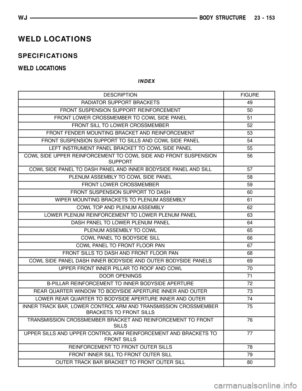
WELD LOCATIONS
SPECIFICATIONS
WELD LOCATIONS
INDEX
DESCRIPTION FIGURE
RADIATOR SUPPORT BRACKETS 49
FRONT SUSPENSION SUPPORT REINFORCEMENT 50
FRONT LOWER CROSSMEMBER TO COWL SIDE PANEL 51
FRONT SILL TO LOWER CROSSMEMBER 52
FRONT FENDER MOUNTING BRACKET AND REINFORCEMENT 53
FRONT SUSPENSION SUPPORT TO SILLS AND COWL SIDE PANEL 54
LEFT INSTRUMENT PANEL BRACKET TO COWL SIDE PANEL 55
COWL SIDE UPPER REINFORCEMENT TO COWL SIDE AND FRONT SUSPENSION
SUPPORT56
COWL SIDE PANEL TO DASH PANEL AND INNER BODYSIDE PANEL AND SILL 57
PLENUM ASSEMBLY TO COWL SIDE PANEL 58
FRONT LOWER CROSSMEMBER 59
FRONT SUSPENSION SUPPORT TO DASH 60
WIPER MOUNTING BRACKETS TO PLENUM ASSEMBLY 61
COWL TOP AND PLENUM ASSEMBLY 62
LOWER PLENUM REINFORCEMENT TO LOWER PLENUM PANEL 63
DASH PANEL TO LOWER PLENUM PANEL 64
PLENUM ASSEMBLY TO COWL 65
COWL PANEL TO BODYSIDE SILL 66
COWL PANEL TO FRONT FLOOR PAN 67
FRONT SILLS TO DASH AND FRONT FLOOR PAN 68
COWL SIDE PANEL DASH INNER BODYSIDE AND OUTER BODYSIDE PANELS 69
UPPER FRONT INNER PILLAR TO ROOF AND COWL 70
DOOR OPENINGS 71
B-PILLAR REINFORCEMENT TO INNER BODYSIDE APERTURE 72
REAR QUARTER WINDOW TO BODYSIDE APERTURE INNER AND OUTER 73
LOWER REAR QUARTER TO BODYSIDE APERTURE INNER AND OUTER 74
INNER TRACK BAR, LOWER CONTROL ARM AND TRANSMISSION CROSSMEMBER
BRACKETS TO FRONT SILLS75
TRANSMISSION CROSSMEMBER BRACKET AND REINFORCEMENT TO FRONT
SILLS76
UPPER SILLS AND UPPER CONTROL ARM REINFORCEMENT AND BRACKETS TO
FRONT SILLS77
REINFORCEMENT TO FRONT OUTER SILLS 78
FRONT INNER SILL TO FRONT OUTER SILL 79
OUTER TRACK BAR BRACKET TO FRONT OUTER SILL 80
WJBODY STRUCTURE 23 - 153
Page 2048 of 2199
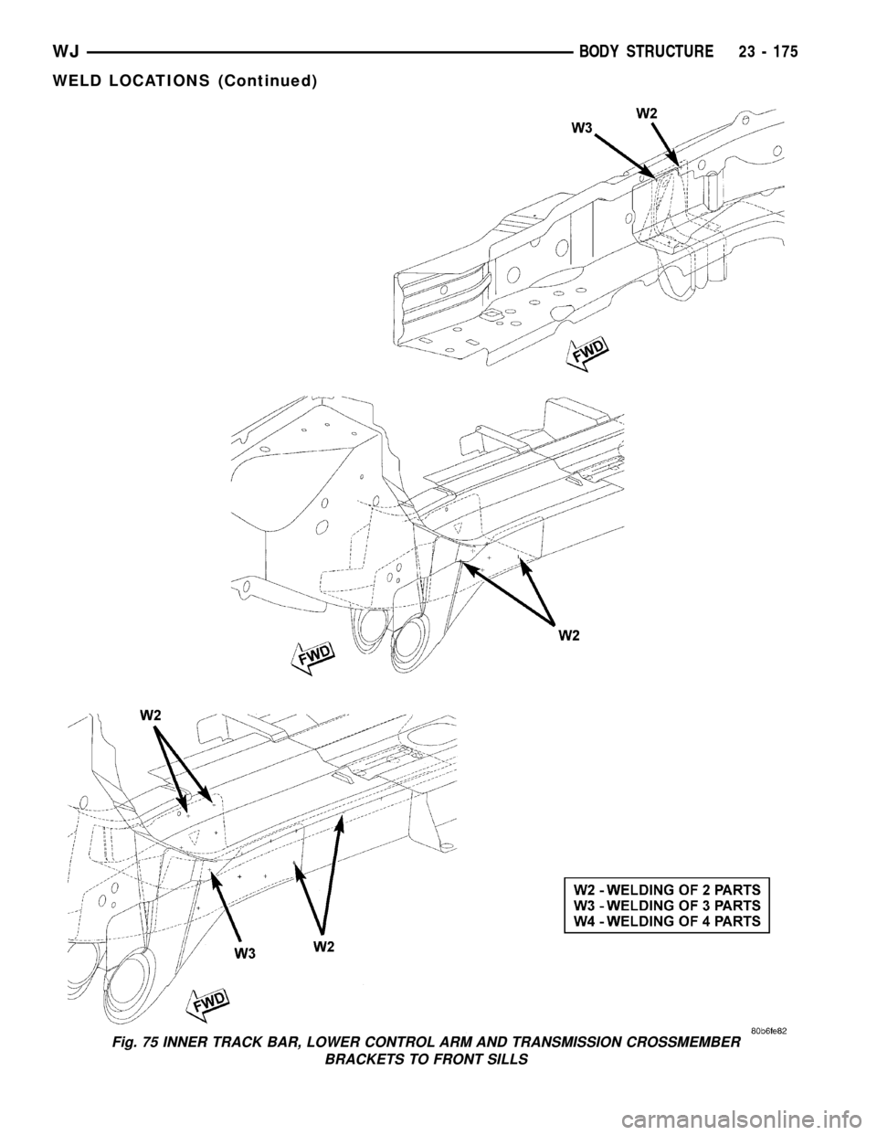
Fig. 75 INNER TRACK BAR, LOWER CONTROL ARM AND TRANSMISSION CROSSMEMBER
BRACKETS TO FRONT SILLS
WJBODY STRUCTURE 23 - 175
WELD LOCATIONS (Continued)
Page 2052 of 2199
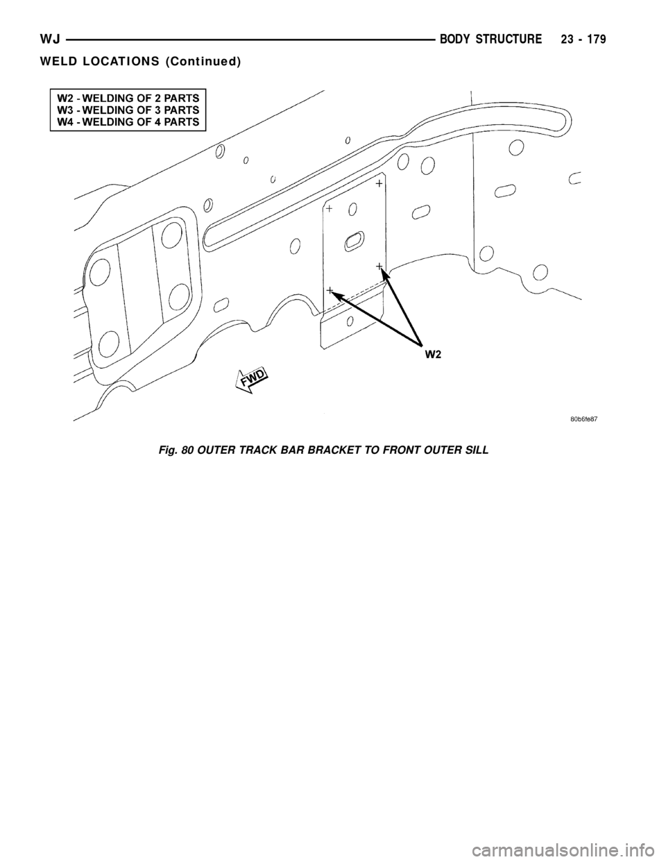
Fig. 80 OUTER TRACK BAR BRACKET TO FRONT OUTER SILL
WJBODY STRUCTURE 23 - 179
WELD LOCATIONS (Continued)