2002 JEEP GRAND CHEROKEE oil change
[x] Cancel search: oil changePage 672 of 2199

8W-02 COMPONENT INDEX
Component Page
A/C Compressor Clutch................. 8W-42
A/C Pressure Transducer................ 8W-42
Accelerator Pedal Position Sensor......... 8W-30
Accessory Delay Relay.................. 8W-64
Adjustable Pedals..................... 8W-30
Airbags............................. 8W-43
Ambient Temperature Sensor............ 8W-45
Antennas............................ 8W-47
Ash Receiver Lamp.................... 8W-44
Auto Shut Down Relay................. 8W-30
Automatic Day/Night Mirror............. 8W-49
Automatic Headlamp Light Sensor/VTSS
LED.............................. 8W-39
Automatic Zone Control Module.......... 8W-42
Back-Up Lamp Relay................... 8W-51
Battery Temperature Sensor............. 8W-30
Battery............................. 8W-20
Blend Door Motor/Actuator.............. 8W-42
Blower Motor......................... 8W-42
Body Control Module................... 8W-45
Boost Pressure Sensor.................. 8W-30
Brake Lamp Switch.................... 8W-33
Camshaft Position Sensor............... 8W-30
Capacitors........................... 8W-30
Cargo Lamp.......................... 8W-44
Center High Mounted Stop Lamp......... 8W-51
Cigar Lighter......................... 8W-41
Circuit Breakers...................... 8W-12
Clockspring.................. 8W-33, 41, 43, 47
Coil On Plugs......................... 8W-30
Coil Rail............................. 8W-30
Combination Flasher................... 8W-52
Compact Disc Changer.................. 8W-47
Controller Antilock Brake............... 8W-35
Coolant Level Sensor................... 8W-45
Courtesy Lamps....................... 8W-44
Crankcase Heater..................... 8W-30
Crankshaft Position Sensor.............. 8W-30
Cylinder Lock Switches................. 8W-61
Data Link Connector................... 8W-18
Diagnostic Junction Port................ 8W-18
EGR Solenoid......................... 8W-30
Electric Brake........................ 8W-54
Electronic Speed Control Servo........... 8W-33
Engine Control Module................. 8W-30
Engine Coolant Temperature Sensor...... 8W-30
Engine Oil Pressure Sensor.............. 8W-30
Engine Starter Motor................... 8W-21
EVAP/Purge Solenoid................... 8W-30
Fog Lamps........................ 8W-50, 51
Fuel Injectors......................... 8W-30
Fuel Pressure Sensor................... 8W-30Component Page
Fuel Pressure Solenoid................. 8W-30
Fuel Pump........................... 8W-30
Fuel Tank Module..................... 8W-30
Fuses............................ 8W-10, 12
Fusible Link....................... 8W-10, 20
Grounds............................. 8W-15
Generator......................... 8W-20, 30
Glove Box Lamp...................... 8W-44
Glow Plugs........................... 8W-30
Headlamp Leveling Motor............... 8W-50
Heated Seats......................... 8W-63
High Beam Headlamps................. 8W-50
Hood Ajar Switch...................... 8W-39
Horns............................... 8W-41
Hydraulic Cooling Module............ 8W-30, 42
Idle Air Control Motor.................. 8W-30
Ignition Switch....................... 8W-10
Impact Sensors....................... 8W-43
Input Speed Sensor.................... 8W-31
Instrument Cluster.................... 8W-40
Intake Air Temperature Sensor........... 8W-30
Intake Port Swirl Actuator.............. 8W-30
Intrusion Transceiver Module............ 8W-49
Junction Block........................ 8W-12
Knock Sensor......................... 8W-30
Lamp Assemblies................... 8W-51, 52
Leak Detection Pump.................. 8W-30
License Lamps........................ 8W-51
Liftgate............................. 8W-61
Line Pressure Sensor................... 8W-31
Low Beam Headlamps.................. 8W-50
Low Beam Relay...................... 8W-50
Low Beam/Daytime Running Lamp Relay . . . 8W-50
Lumbar Motor........................ 8W-63
Lumbar Switch....................... 8W-63
Manifold Absolute Pressure Sensor........ 8W-30
Manual Temperature Control............. 8W-42
Mass Air Flow Sensor.................. 8W-30
Memory Set Switch................. 8W-62, 63
Mode Door Motor/Actuator............... 8W-42
Multi-Function Switch............... 8W-50, 53
Output Speed Sensor................... 8W-31
Overhead Map/Courtesy Lamp........... 8W-44
Oxygen Sensors....................... 8W-30
Park Brake Switch..................... 8W-40
Park Lamp........................... 8W-50
Park/Neutral Position Switch............ 8W-31
Park/Turn Signal Lamps................ 8W-50
Power Amplifier....................... 8W-47
Power Connector...................... 8W-41
Power Distribution Center............... 8W-10
Power Mirrors........................ 8W-62
WJ8W-02 COMPONENT INDEX 8W - 02 - 1
Page 1049 of 2199
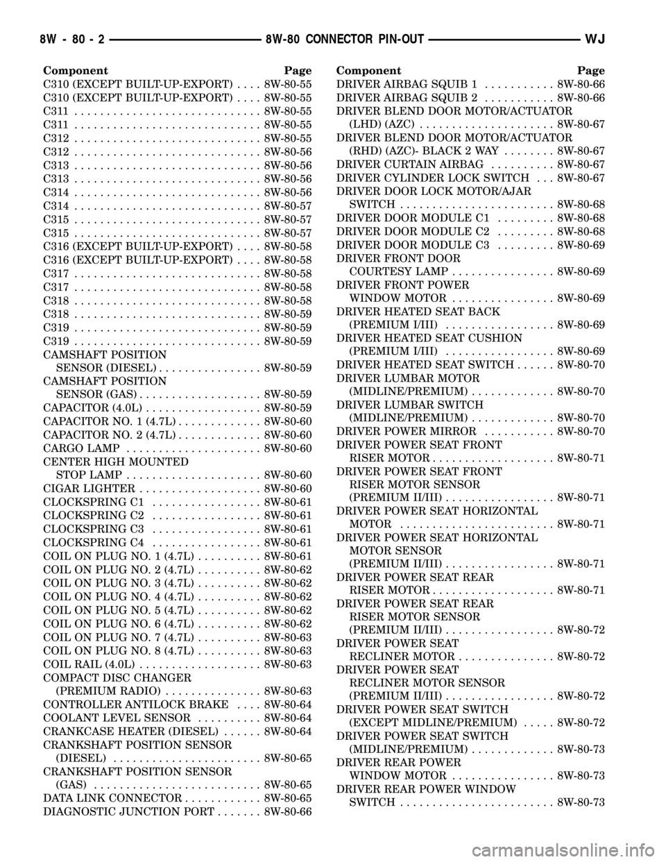
Component Page
C310 (EXCEPT BUILT-UP-EXPORT).... 8W-80-55
C310 (EXCEPT BUILT-UP-EXPORT).... 8W-80-55
C311 ............................. 8W-80-55
C311 ............................. 8W-80-55
C312............................. 8W-80-55
C312............................. 8W-80-56
C313............................. 8W-80-56
C313............................. 8W-80-56
C314............................. 8W-80-56
C314............................. 8W-80-57
C315............................. 8W-80-57
C315............................. 8W-80-57
C316 (EXCEPT BUILT-UP-EXPORT).... 8W-80-58
C316 (EXCEPT BUILT-UP-EXPORT).... 8W-80-58
C317............................. 8W-80-58
C317............................. 8W-80-58
C318............................. 8W-80-58
C318............................. 8W-80-59
C319............................. 8W-80-59
C319............................. 8W-80-59
CAMSHAFT POSITION
SENSOR (DIESEL)................ 8W-80-59
CAMSHAFT POSITION
SENSOR (GAS)................... 8W-80-59
CAPACITOR (4.0L).................. 8W-80-59
CAPACITOR NO. 1 (4.7L)............. 8W-80-60
CAPACITOR NO. 2 (4.7L)............. 8W-80-60
CARGO LAMP..................... 8W-80-60
CENTER HIGH MOUNTED
STOP LAMP..................... 8W-80-60
CIGAR LIGHTER................... 8W-80-60
CLOCKSPRING C1................. 8W-80-61
CLOCKSPRING C2................. 8W-80-61
CLOCKSPRING C3................. 8W-80-61
CLOCKSPRING C4................. 8W-80-61
COIL ON PLUG NO. 1 (4.7L).......... 8W-80-61
COIL ON PLUG NO. 2 (4.7L).......... 8W-80-62
COIL ON PLUG NO. 3 (4.7L).......... 8W-80-62
COIL ON PLUG NO. 4 (4.7L).......... 8W-80-62
COIL ON PLUG NO. 5 (4.7L).......... 8W-80-62
COIL ON PLUG NO. 6 (4.7L).......... 8W-80-62
COIL ON PLUG NO. 7 (4.7L).......... 8W-80-63
COIL ON PLUG NO. 8 (4.7L).......... 8W-80-63
COIL RAIL (4.0L)................... 8W-80-63
COMPACT DISC CHANGER
(PREMIUM RADIO)............... 8W-80-63
CONTROLLER ANTILOCK BRAKE.... 8W-80-64
COOLANT LEVEL SENSOR.......... 8W-80-64
CRANKCASE HEATER (DIESEL)...... 8W-80-64
CRANKSHAFT POSITION SENSOR
(DIESEL)....................... 8W-80-65
CRANKSHAFT POSITION SENSOR
(GAS).......................... 8W-80-65
DATA LINK CONNECTOR............ 8W-80-65
DIAGNOSTIC JUNCTION PORT....... 8W-80-66Component Page
DRIVER AIRBAG SQUIB 1........... 8W-80-66
DRIVER AIRBAG SQUIB 2........... 8W-80-66
DRIVER BLEND DOOR MOTOR/ACTUATOR
(LHD) (AZC)..................... 8W-80-67
DRIVER BLEND DOOR MOTOR/ACTUATOR
(RHD) (AZC)- BLACK 2 WAY........ 8W-80-67
DRIVER CURTAIN AIRBAG.......... 8W-80-67
DRIVER CYLINDER LOCK SWITCH . . . 8W-80-67
DRIVER DOOR LOCK MOTOR/AJAR
SWITCH........................ 8W-80-68
DRIVER DOOR MODULE C1......... 8W-80-68
DRIVER DOOR MODULE C2......... 8W-80-68
DRIVER DOOR MODULE C3......... 8W-80-69
DRIVER FRONT DOOR
COURTESY LAMP................ 8W-80-69
DRIVER FRONT POWER
WINDOW MOTOR................ 8W-80-69
DRIVER HEATED SEAT BACK
(PREMIUM I/III)................. 8W-80-69
DRIVER HEATED SEAT CUSHION
(PREMIUM I/III)................. 8W-80-69
DRIVER HEATED SEAT SWITCH...... 8W-80-70
DRIVER LUMBAR MOTOR
(MIDLINE/PREMIUM)............. 8W-80-70
DRIVER LUMBAR SWITCH
(MIDLINE/PREMIUM)............. 8W-80-70
DRIVER POWER MIRROR........... 8W-80-70
DRIVER POWER SEAT FRONT
RISER MOTOR................... 8W-80-71
DRIVER POWER SEAT FRONT
RISER MOTOR SENSOR
(PREMIUM II/III)................. 8W-80-71
DRIVER POWER SEAT HORIZONTAL
MOTOR........................ 8W-80-71
DRIVER POWER SEAT HORIZONTAL
MOTOR SENSOR
(PREMIUM II/III)................. 8W-80-71
DRIVER POWER SEAT REAR
RISER MOTOR................... 8W-80-71
DRIVER POWER SEAT REAR
RISER MOTOR SENSOR
(PREMIUM II/III)................. 8W-80-72
DRIVER POWER SEAT
RECLINER MOTOR............... 8W-80-72
DRIVER POWER SEAT
RECLINER MOTOR SENSOR
(PREMIUM II/III)................. 8W-80-72
DRIVER POWER SEAT SWITCH
(EXCEPT MIDLINE/PREMIUM)..... 8W-80-72
DRIVER POWER SEAT SWITCH
(MIDLINE/PREMIUM)............. 8W-80-73
DRIVER REAR POWER
WINDOW MOTOR................ 8W-80-73
DRIVER REAR POWER WINDOW
SWITCH........................ 8W-80-73
8W - 80 - 2 8W-80 CONNECTOR PIN-OUTWJ
Page 1110 of 2199
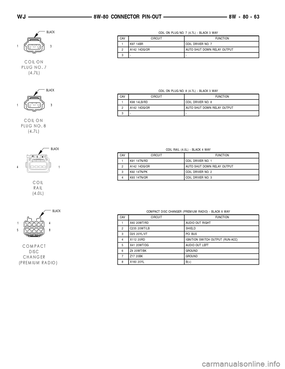
COIL ON PLUG NO. 7 (4.7L) - BLACK 3 WAY
CAV CIRCUIT FUNCTION
1 K97 14BR COIL DRIVER NO. 7
2 A142 14DG/OR AUTO SHUT DOWN RELAY OUTPUT
3- -
COIL ON PLUG NO. 8 (4.7L) - BLACK 3 WAY
CAV CIRCUIT FUNCTION
1 K98 14LB/RD COIL DRIVER NO. 8
2 A142 14DG/OR AUTO SHUT DOWN RELAY OUTPUT
3- -
COIL RAIL (4.0L) - BLACK 4 WAY
CAV CIRCUIT FUNCTION
1 K91 14TN/RD COIL DRIVER NO. 1
2 A142 14DG/OR AUTO SHUT DOWN RELAY OUTPUT
3 K92 14TN/PK COIL DRIVER NO. 2
4 K93 14TN/OR COIL DRIVER NO. 3
COMPACT DISC CHANGER (PREMIUM RADIO) - BLACK 8 WAY
CAV CIRCUIT FUNCTION
1 X40 20WT/RD AUDIO OUT RIGHT
2 C235 20WT/LB SHIELD
3 D25 20YL/VT PCI BUS
4 X112 20RD IGNITION SWITCH OUTPUT (RUN-ACC)
5 X41 20WT/DG AUDIO OUT LEFT
6 Z4 20WT/BK GROUND
7 Z17 20BK GROUND
8 X160 20YL B(+)
WJ8W-80 CONNECTOR PIN-OUT 8W - 80 - 63
Page 1179 of 2199
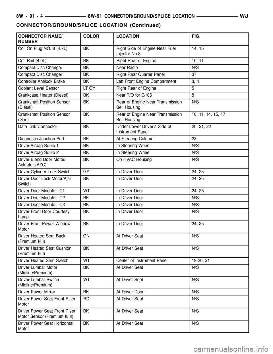
CONNECTOR NAME/
NUMBERCOLOR LOCATION FIG.
Coil On Plug NO. 8 (4.7L) BK Right Side of Engine Near Fuel
Injector No.814, 15
Coil Rail (4.0L) BK Right Rear of Engine 10, 11
Compact Disc Changer BK Near Radio N/S
Compact Disc Changer BK Right Rear Quarter Panel 37
Controller Antilock Brake BK Left Front Engine Compartment 3, 4
Coolant Level Sensor LT GY Right Rear of Engine 5
Crankcase Heater (Diesel) BK Near T/O for G105 8
Crankshaft Position Sensor
(Diesel)BK Rear of Engine Near Transmission
Bell HousingN/S
Crankshaft Position Sensor
(Gas)BK Rear of Engine Near Transmission
Bell Housing10, 11, 14, 15, 17
Data Link Connector BK Under Lower Driver's Side of
Instrument Panel20, 21, 22
Diagnostic Junction Port BK At Steering Column 23
Driver Airbag Squib 1 BK In Steering Wheel N/S
Driver Airbag Squib 2 BK In Steering Wheel N/S
Driver Blend Door Motor/
Actuator (AZC)BK On HVAC Housing N/S
Driver Cylinder Lock Switch GY In Driver Door 24, 25
Driver Door Lock Motor/Ajar
SwitchBK In Driver Door 24, 25
Driver Door Module - C1 WT In Driver Door 24, 25
Driver Door Module - C2 BK In Driver Door N/S
Driver Door Module - C3 BK In Driver Door N/S
Driver Front Door Courtesy
LampBK In Driver Door N/S
Driver Front Power Window
MotorBK In Driver Door 24, 25
Driver Heated Seat Back
(Premium I/III)GN At Driver Seat N/S
Driver Heated Seat Cushion
(Premium I/III)BK At Driver Seat N/S
Driver Heated Seat Switch WT Center of Instrument Panel 19 20, 21
Driver Lumbar Motor
(Midline/Premium)BK At Driver Seat N/S
Driver Lumbar Switch
(Midline/Premium)WT At Driver Seat N/S
Driver Power Mirror BK At Driver Door N/S
Driver Power Seat Front Riser
MotorRD At Driver Seat N/S
Driver Power Seat Front Riser
Motor Sensor (Premium II/III)BK At Driver Seat N/S
Driver Power Seat Horizontal
MotorBK At Driver Seat N/S
8W - 91 - 4 8W-91 CONNECTOR/GROUND/SPLICE LOCATIONWJ
CONNECTOR/GROUND/SPLICE LOCATION (Continued)
Page 1227 of 2199
the same time, the power distribution system was
designed to provide ready access to these electrical
distribution points for the vehicle technician to use
when conducting diagnosis and repair of faulty cir-
cuits. The power distribution system can also prove
useful for the sourcing of additional electrical circuits
that may be required to provide the electrical current
needed to operate accessories that the vehicle owner
may choose to have installed in the aftermarket.
NOTE: DO NOT ATTEMPT TO SWAP POWER DIS-
TRIBUTION CENTERS FROM ONE VEHICLE TO
ANOTHER. MOST OF THESE ASSEMBLIES ARE
VEHICLE FEATURE SPECIFIC AND THEREFORE
NOT INTERCHANGEABLE. ALWAYS USE THE COR-
RECT PART NUMBERED ASSEMBLY WHEN DIAG-
NOSING OR REPLACING A POWER DISTRIBUTION
CENTER.
SPECIAL TOOLS
POWER DISTRIBUTION SYSTEMS
CIGAR LIGHTER OUTLET
DESCRIPTION
A cigar lighter outlet is standard equipment on
this model. On models equipped with the optional
Smoker's Package, the cigar lighter knob and heating
element are included. On models without the Smok-
er's Package, the cigar lighter outlet is equipped with
a snap fit plastic cap and is treated as an extra
accessory power outlet. The cigar lighter outlet is
installed in the instrument panel center lower bezel,
which is located near the bottom of the instrument
panel center stack area, below the heater and air
conditioner controls. The cigar lighter outlet is
secured by a snap fit within the center lower bezel.The cigar lighter outlet, plastic cap and the knob
and heating element unit are available for service
replacement. These components cannot be repaired
and, if faulty or damaged, they must be replaced.
OPERATION
The cigar lighter consists of two major components:
a knob and heating element unit, and the cigar
lighter base or outlet shell. The receptacle shell is
connected to ground, and an insulated contact in the
bottom of the shell is connected to battery current.
The cigar lighter receives battery voltage from a fuse
in the junction block when the ignition switch is in
the Accessory or On positions.
The cigar lighter knob and heating element are
encased within a spring-loaded housing, which also
features a sliding protective heat shield. When the
knob and heating element are inserted in the outlet
shell, the heating element resistor coil is grounded
through its housing to the outlet shell. If the cigar
lighter knob is pushed inward, the heat shield slides
up toward the knob exposing the heating element,
and the heating element extends from the housing
toward the insulated contact in the bottom of the
outlet shell.
Two small spring-clip retainers are located on
either side of the insulated contact inside the bottom
of the outlet shell. These clips engage and hold the
heating element against the insulated contact long
enough for the resistor coil to heat up. When the
heating element is engaged with the contact, battery
current can flow through the resistor coil to ground,
causing the resistor coil to heat.
When the resistor coil becomes sufficiently heated,
excess heat radiates from the heating element caus-
ing the spring-clips to expand. Once the spring-clips
expand far enough to release the heating element,
the spring-loaded housing forces the knob and heat-
ing element to pop back outward to their relaxed
position. When the cigar lighter knob and element
are pulled out of the outlet shell, the protective heat
shield slides downward on the housing so that the
heating element is recessed and shielded around its
circumference for safety.
DIAGNOSIS AND TESTING - CIGAR LIGHTER
OUTLET
For complete circuit diagrams, refer toHorn/Ci-
gar Lighter/Power Outletin Wiring Diagrams.
(1) Check the fused B(+) fuse in the junction block.
If OK, go to Step 2. If not OK, repair the shorted cir-
cuit or component as required and replace the faulty
fuse.
(2) Turn the ignition switch to the On position.
Check for battery voltage at the fused B(+) fuse in
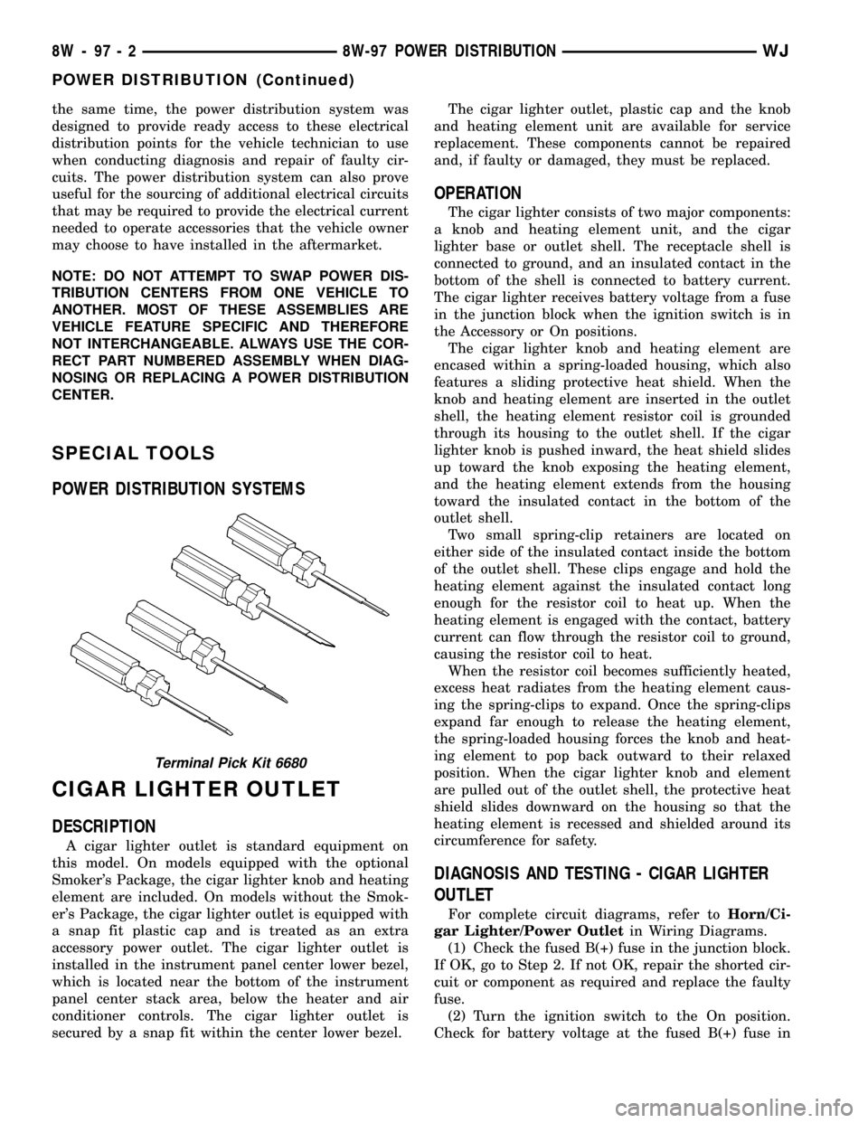
Terminal Pick Kit 6680
8W - 97 - 2 8W-97 POWER DISTRIBUTIONWJ
POWER DISTRIBUTION (Continued)
Page 1249 of 2199
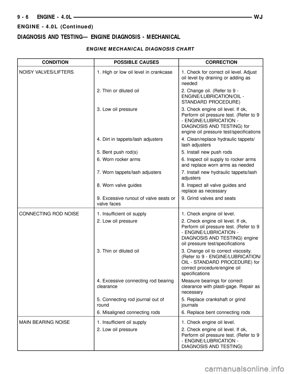
DIAGNOSIS AND TESTINGÐ ENGINE DIAGNOSIS - MECHANICAL
ENGINE MECHANICAL DIAGNOSIS CHART
CONDITION POSSIBLE CAUSES CORRECTION
NOISY VALVES/LIFTERS 1. High or low oil level in crankcase 1. Check for correct oil level. Adjust
oil level by draining or adding as
needed
2. Thin or diluted oil 2. Change oil. (Refer to 9 -
ENGINE/LUBRICATION/OIL -
STANDARD PROCEDURE)
3. Low oil pressure 3. Check engine oil level. If ok,
Perform oil pressure test. (Refer to 9
- ENGINE/LUBRICATION -
DIAGNOSIS AND TESTING) for
engine oil pressure test/specifications
4. Dirt in tappets/lash adjusters 4. Clean/replace hydraulic tappets/
lash adjusters
5. Bent push rod(s) 5. Install new push rods
6. Worn rocker arms 6. Inspect oil supply to rocker arms
and replace worn arms as needed
7. Worn tappets/lash adjusters 7. Install new hydraulic tappets/lash
adjusters
8. Worn valve guides 8. Inspect all valve guides and
replace as necessary
9. Excessive runout of valve seats or
valve faces9. Grind valves and seats
CONNECTING ROD NOISE 1. Insufficient oil supply 1. Check engine oil level.
2. Low oil pressure 2. Check engine oil level. If ok,
Perform oil pressure test. (Refer to 9
- ENGINE/LUBRICATION -
DIAGNOSIS AND TESTING) engine
oil pressure test/specifications
3. Thin or diluted oil 3. Change oil to correct viscosity.
(Refer to 9 - ENGINE/LUBRICATION/
OIL - STANDARD PROCEDURE) for
correct procedure/engine oil
specifications
4. Excessive connecting rod bearing
clearanceMeasure bearings for correct
clearance with plasti-gage. Repair as
necessary
5. Connecting rod journal out of
round5. Replace crankshaft or grind
journals
6. Misaligned connecting rods 6. Replace bent connecting rods
MAIN BEARING NOISE 1. Insufficient oil supply 1. Check engine oil level.
2. Low oil pressure 2. Check engine oil level. If ok,
Perform oil pressure test. (Refer to 9
- ENGINE/LUBRICATION -
DIAGNOSIS AND TESTING)
9 - 6 ENGINE - 4.0LWJ
ENGINE - 4.0L (Continued)
Page 1250 of 2199
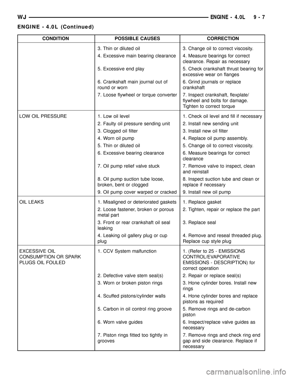
CONDITION POSSIBLE CAUSES CORRECTION
3. Thin or diluted oil 3. Change oil to correct viscosity.
4. Excessive main bearing clearance 4. Measure bearings for correct
clearance. Repair as necessary
5. Excessive end play 5. Check crankshaft thrust bearing for
excessive wear on flanges
6. Crankshaft main journal out of
round or worn6. Grind journals or replace
crankshaft
7. Loose flywheel or torque converter 7. Inspect crankshaft, flexplate/
flywheel and bolts for damage.
Tighten to correct torque
LOW OIL PRESSURE 1. Low oil level 1. Check oil level and fill if necessary
2. Faulty oil pressure sending unit 2. Install new sending unit
3. Clogged oil filter 3. Install new oil filter
4. Worn oil pump 4. Replace oil pump assembly.
5. Thin or diluted oil 5. Change oil to correct viscosity.
6. Excessive bearing clearance 6. Measure bearings for correct
clearance
7. Oil pump relief valve stuck 7. Remove valve to inspect, clean
and reinstall
8. Oil pump suction tube loose,
broken, bent or clogged8. Inspect suction tube and clean or
replace if necessary
9. Oil pump cover warped or cracked 9. Install new oil pump
OIL LEAKS 1. Misaligned or deteriorated gaskets 1. Replace gasket
2. Loose fastener, broken or porous
metal part2. Tighten, repair or replace the part
3. Front or rear crankshaft oil seal
leaking3. Replace seal
4. Leaking oil gallery plug or cup
plug4. Remove and reseal threaded plug.
Replace cup style plug
EXCESSIVE OIL
CONSUMPTION OR SPARK
PLUGS OIL FOULED1. CCV System malfunction 1. (Refer to 25 - EMISSIONS
CONTROL/EVAPORATIVE
EMISSIONS - DESCRIPTION) for
correct operation
2. Defective valve stem seal(s) 2. Repair or replace seal(s)
3. Worn or broken piston rings 3. Hone cylinder bores. Install new
rings
4. Scuffed pistons/cylinder walls 4. Hone cylinder bores and replace
pistons as required
5. Carbon in oil control ring groove 5. Remove rings and de-carbon
piston
6. Worn valve guides 6. Inspect/replace valve guides as
necessary
7. Piston rings fitted too tightly in
grooves7. Remove rings and check ring end
gap and side clearance. Replace if
necessary
WJENGINE - 4.0L 9 - 7
ENGINE - 4.0L (Continued)
Page 1276 of 2199
(16) Install the serpentine drive belt (Refer to 7 -
COOLING/ACCESSORY DRIVE/DRIVE BELTS -
INSTALLATION).
NOTE: During installation, lubricate the hydraulic
valve tappets and all valve components with
MoparTEngine Oil Supplement, or equivalent. TheMoparTEngine Oil Supplement, or equivalent must
remain with the engine oil for at least 1609 km
(1,000 miles). The oil supplement need not be
drained until the next scheduled oil change.
(17) Install the radiator (Refer to 7 - COOLING/
ENGINE/RADIATOR - INSTALLATION).
(18) Check the ignition timing and adjust as nec-
essary.
(19) Install the grille and bumper, if removed.
(20) Connect negative cable to battery.
CONNECTING ROD BEARINGS
STANDARD PROCEDURE - FITTING
CONNECTING ROD BEARINGS
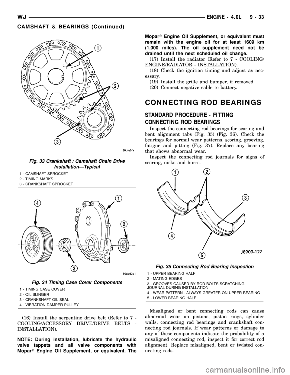
Inspect the connecting rod bearings for scoring and
bent alignment tabs (Fig. 35) (Fig. 36). Check the
bearings for normal wear patterns, scoring, grooving,
fatigue and pitting (Fig. 37). Replace any bearing
that shows abnormal wear.
Inspect the connecting rod journals for signs of
scoring, nicks and burrs.
Misaligned or bent connecting rods can cause
abnormal wear on pistons, piston rings, cylinder
walls, connecting rod bearings and crankshaft con-
necting rod journals. If wear patterns or damage to
any of these components indicate the probability of a
misaligned connecting rod, inspect it for correct rod
alignment. Replace misaligned, bent or twisted con-
necting rods.
Fig. 33 Crankshaft / Camshaft Chain Drive
InstallationÐTypical
1 - CAMSHAFT SPROCKET
2 - TIMING MARKS
3 - CRANKSHAFT SPROCKET
Fig. 34 Timing Case Cover Components
1 - TIMING CASE COVER
2 - OIL SLINGER
3 - CRANKSHAFT OIL SEAL
4 - VIBRATION DAMPER PULLEY
Fig. 35 Connecting Rod Bearing Inspection
1 - UPPER BEARING HALF
2 - MATING EDGES
3 - GROOVES CAUSED BY ROD BOLTS SCRATCHING
JOURNAL DURING INSTALLATION
4 - WEAR PATTERN - ALWAYS GREATER ON UPPER BEARING
5 - LOWER BEARING HALF
WJENGINE - 4.0L 9 - 33
CAMSHAFT & BEARINGS (Continued)