2002 JEEP GRAND CHEROKEE gas type
[x] Cancel search: gas typePage 567 of 2199

PASSENGER AIRBAG
DESCRIPTION
The rearward facing surface of the instrument
panel top pad above the glove box is the most visible
part of the passenger airbag (Fig. 31). The passenger
airbag is located above the glove box opening in front
of the front seat passenger seating position within
the instrument panel. The stamped steel passenger
airbag door is secured on the back of the instrument
panel top pad armature between the two passenger
side panel outlets. A stamped metal reinforcement is
secured to the instrument panel top pad armature
near the upper edge of the passenger airbag door
opening, and helps to define a predetermined hinge
line beneath the decorative cover of the top pad. The
instrument panel passenger side bezel is secured to
the airbag door from behind with four screws.
Located behind the passenger airbag door within
the instrument panel is the passenger airbag unit.
The passenger airbag unit used in this model is a
multistage, Next Generation-type that complies with
revised federal airbag standards to deploy with less
force than those used in some prior models. The pas-
senger airbag unit consists of an extruded aluminum
housing, a molded plastic inner airbag cushion dust
cover, the airbag cushion, and the airbag inflator.
The airbag housing contains the airbag inflator,
while the inner dust cover contains the folded airbag
cushion. The dust cover completely encloses the air-
bag cushion and is permanently retained to the hous-
ing. The passenger airbag unit is secured with four
screws to the instrument panel structural duct. Con-cealed beneath the instrument panel top pad are the
passenger airbag door, the folded airbag cushion, the
airbag retainer or housing, and the airbag inflator.
The airbag cushion is constructed of a coated nylon
fabric. The airbag inflator is a dual-initiator, hybrid-
type unit that is secured to and sealed within the air-
bag housing. A short four-wire pigtail harness with a
keyed, yellow connector insulator connects the two
inflator initiators to the vehicle electrical system
through a dedicated take out and connector of the
instrument panel wire harness.
The passenger airbag cannot be repaired, and must
be replaced if deployed, faulty, or in any way dam-
aged. The passenger airbag cannot be repaired, and
must be replaced if faulty or in any way damaged.
The passenger airbag door is serviced only as a unit
with the instrument panel top pad. Following a pas-
senger airbag deployment, the passenger airbag and
the instrument panel top pad must be replaced. If
inspection reveals that the passenger airbag mount-
ing points on the instrument panel structural duct
have been cracked or damaged, the instrument panel
structural duct assembly must also be replaced.
OPERATION
The multistage passenger airbag is deployed by
electrical signals generated by the Airbag Control
Module (ACM) through the passenger airbag squib 1
and squib 2 circuits to the two initiators in the air-
bag inflator. By using two initiators, the airbag can
be deployed at multiple levels of force. The force level
is controlled by the ACM to suit the monitored
impact conditions by providing one of four delay
intervals between the electrical signals provided to
the two initiators. The longer the delay between
these signals, the less forcefully the airbag will
deploy.
The hybrid-type inflator assembly includes a small
canister of highly compressed gas. When the ACM
sends the proper electrical signal to the airbag infla-
tor, the initiator generates enough heat to ignite
chemical pellets within the inflator. Once ignited,
these chemical pellets burn rapidly and produce the
pressure necessary to rupture a containment disk in
the pressurized gas canister. The inflator and gas
canister are sealed to the airbag cushion so that all
of the released inert gas is directed into the airbag
cushion, causing the cushion to inflate. As the cush-
ion inflates, the passenger airbag door will bend back
the instrument panel top pad at the predetermined
hinge line, then fold back over the top of the instru-
ment panel and out of the way. Following an airbag
deployment, the airbag cushion quickly deflates by
venting the inert gas through vent holes within the
fabric used to construct the sides of the airbag cush-
ion.
Fig. 31 Passenger Airbag Door
1 - BEZEL
2-TOPPAD
3 - PASSENGER AIRBAG DOOR
4 - GLOVE BOX DOOR
8O - 30 RESTRAINTSWJ
Page 576 of 2199
SIDE CURTAIN AIRBAG
DESCRIPTION
Optional side curtain airbags are available for this
model when it is also equipped with dual front air-
bags. These airbags are passive, inflatable, Supple-
mental Restraint System (SRS) components, and
vehicles with this equipment can be readily identified
by a molded identification trim button with the ªSRS
- AIRBAGº logo located on the headliner above each
B-pillar (Fig. 42). This system is designed to reduce
injuries to the vehicle occupants in the event of a
side impact collision.
Vehicles equipped with side curtain airbags have
two individually controlled curtain airbag units.
These airbag units are concealed and mounted above
the headliner where they are each secured to one of
the roof side rails (Fig. 43). Each folded airbag cush-
ion is contained within a long extruded plastic chan-
nel that extends along the roof rail from the A-pillar
at the front of the vehicle to just behind the C-pillar
at the rear of the vehicle. One tether extends down
the A-pillar from the front of the airbag cushion, and
a second tether extends to the roof rail above the
D-pillar. The ends of these tethers are secured to
slots in the sheet metal with metal hooks retained by
plastic anchor clips.
The hybrid-type inflator for each airbag is secured
to the roof rail at the rear of the airbag unit between
the C-pillar and the D-pillar, and is connected to the
airbag cushion by a long tubular manifold. The infla-
tor bracket and the extruded airbag cushion channel
are secured with both plastic push-in fasteners and
screws to the roof rail. A dedicated two-wire take out
and connector of the body wire harness is routed for-
ward from the D-pillar to the airbag inflator.The side curtain airbag unit cannot be adjusted or
repaired and must be replaced if deployed, faulty, or
in any way damaged. Once a side curtain airbag has
been deployed, the complete airbag unit, the head-
liner, the upper A, B, and C-pillar trim, and all other
visibly damaged components must be replaced.
OPERATION
Each side curtain airbag is deployed individually
by an electrical signal generated by the Airbag Con-
trol Module (ACM) to which it is connected through
left or right curtain airbag line 1 and line 2 (or
squib) circuits. The hybrid-type inflator assembly for
each airbag contains a small canister of highly com-
pressed gas. When the ACM sends the proper electri-
cal signal to the airbag inflator, the electrical energy
creates enough heat to ignite chemical pellets within
the inflator. Once ignited, these chemicals burn rap-
idly and produce the pressure necessary to rupture a
containment disk in the pressurized gas canister. The
inflator and gas canister are sealed and connected to
a tubular manifold so that all of the released inert
gas is directed into the folded side curtain airbag
cushion, causing the cushion to inflate.
As the airbag cushion inflates it will drop down
from the roof rail between the edge of the headliner
and the side glass/body pillars to form a curtain-like
cushion to protect the vehicle occupants during a side
impact collision. The front and rear tethers keep the
side curtain bag taut, thus ensuring that the bag will
deploy in the proper position. Following the airbag
deployment, the airbag cushion quickly deflates by
venting the inert gas through the loose weave of the
cushion fabric, and the deflated cushion hangs down
loosely from the roof rail.
REMOVAL
The following procedure is for replacement of a
faulty or damaged side curtain airbag. If the airbag
is faulty or damaged, but not deployed, review the
recommended procedures for handling non-deployed
supplemental restraints. (Refer to 8 - ELECTRICAL/
RESTRAINTS - STANDARD PROCEDURE - HAN-
DLING NON-DEPLOYED SUPPLEMENTAL
RESTRAINTS). If the side curtain airbag has been
deployed, review the recommended procedures for
service after a supplemental restraint deployment
before removing the airbag from the vehicle. (Refer to
8 - ELECTRICAL/RESTRAINTS - STANDARD PRO-
CEDURE - SERVICE AFTER A SUPPLEMENTAL
RESTRAINT DEPLOYMENT).
Fig. 42 SRS Logo
WJRESTRAINTS 8O - 39
Page 1252 of 2199
DIAGNOSIS AND TESTINGÐREAR SEAL AREA
LEAKS
Since it is sometimes difficult to determine the
source of an oil leak in the rear seal area of the
engine, a more involved inspection is necessary. The
following steps should be followed to help pinpoint
the source of the leak.
If the leakage occurs at the crankshaft rear oil seal
area:
(1) Disconnect the battery.
(2) Raise the vehicle.
(3) Remove torque converter or clutch housing
cover and inspect rear of block for evidence of oil.
Use a black light to check for the oil leak:
(a) Circular spray pattern generally indicates
seal leakage or crankshaft damage.
(b) Where leakage tends to run straight down,
possible causes are a porous block, distributor seal,
camshaft bore cup plugs, oil galley pipe plugs, oil
filter runoff, and main bearing cap to cylinder
block mating surfaces.
(4) If no leaks are detected, pressurized the crank-
case as outlined in (Refer to 9 - ENGINE/LUBRICA-
TION - DIAGNOSIS AND TESTING)
CAUTION: Do not exceed 20.6 kPa (3 psi).
(5) If the leak is not detected, very slowly turn the
crankshaft and watch for leakage. If a leak is
detected between the crankshaft and seal while
slowly turning the crankshaft, it is possible the
crankshaft seal surface is damaged. The seal area on
the crankshaft could have minor nicks or scratches
that can be polished out with emery cloth.
CAUTION: Use extreme caution when crankshaft
polishing is necessary to remove minor nicks or
scratches. The crankshaft seal flange is specially
machined to complement the function of the rear oil
seal.
(6) For bubbles that remain steady with shaft
rotation, no further inspection can be done until dis-
assembled. Refer to the service DiagnosisÐMechani-
cal, under the Oil Leak row, for components
inspections on possible causes and corrections.
(7) After the oil leak root cause and appropriate
corrective action have been identified, (Refer to 9 -
ENGINE/ENGINE BLOCK/CRANKSHAFT OIL
SEAL - REAR - REMOVAL), for proper replacement
procedures.
STANDARD PROCEDURE
STANDARD PROCEDURE - FORM-IN-PLACE
GASKETS AND SEALERS
There are numerous places where form-in-place
gaskets are used on the engine. Care must be taken
when applying form-in-place gaskets to assure
obtaining the desired results.Do not use form-in-
place gasket material unless specified.Bead size,
continuity, and location are of great importance. Too
thin a bead can result in leakage while too much can
result in spill-over which can break off and obstruct
fluid feed lines. A continuous bead of the proper
width is essential to obtain a leak-free gasket.
There are numerous types of form-in-place gasket
materials that are used in the engine area. Mopart
Engine RTV GEN II, MopartATF-RTV, and Mopart
Gasket Maker gasket materials, each have different
properties and can not be used in place of the other.
MOPARtENGINE RTV GEN II
MopartEngine RTV GEN II is used to seal com-
ponents exposed to engine oil. This material is a spe-
cially designed black silicone rubber RTV that
retains adhesion and sealing properties when
exposed to engine oil. Moisture in the air causes the
material to cure. This material is available in three
ounce tubes and has a shelf life of one year. After one
year this material will not properly cure. Always
inspect the package for the expiration date before
use.
MOPARtATF RTV
MopartATF RTV is a specifically designed black
silicone rubber RTV that retains adhesion and seal-
ing properties to seal components exposed to auto-
matic transmission fluid, engine coolants, and
moisture. This material is available in three ounce
tubes and has a shelf life of one year. After one year
this material will not properly cure. Always inspect
the package for the expiration date before use.
MOPARtGASKET MAKER
MopartGasket Maker is an anaerobic type gasket
material. The material cures in the absence of air
when squeezed between two metallic surfaces. It will
not cure if left in the uncovered tube. The anaerobic
material is for use between two machined surfaces.
Do not use on flexible metal flanges.
MOPARtGASKET SEALANT
MopartGasket Sealant is a slow drying, perma-
nently soft sealer. This material is recommended for
sealing threaded fittings and gaskets against leakage
of oil and coolant. Can be used on threaded and
machined parts under all temperatures. This mate-
rial is used on engines with multi-layer steel (MLS)
cylinder head gaskets. This material also will pre-
vent corrosion. MopartGasket Sealant is available in
a 13 oz. aerosol can or 4oz./16 oz. can w/applicator.
WJENGINE - 4.0L 9 - 9
ENGINE - 4.0L (Continued)
Page 1253 of 2199
FORM-IN-PLACE GASKET AND SEALER
APPLICATION
Assembling parts using a form-in-place gasket
requires care but it's easier then using precut gaskets.
MopartGasket Maker material should be applied
sparingly 1 mm (0.040 in.) diameter or less of sealant
to one gasket surface. Be certain the material sur-
rounds each mounting hole. Excess material can eas-
ily be wiped off. Components should be torqued in
place within 15 minutes. The use of a locating dowel
is recommended during assembly to prevent smear-
ing material off the location.
MopartEngine RTV GEN II or ATF RTV gasket
material should be applied in a continuous bead
approximately 3 mm (0.120 in.) in diameter. All
mounting holes must be circled. For corner sealing, a
3.17 or 6.35 mm (1/8 or 1/4 in.) drop is placed in the
center of the gasket contact area. Uncured sealant
may be removed with a shop towel. Components
should be torqued in place while the sealant is still
wet to the touch (within 10 minutes). The usage of a
locating dowel is recommended during assembly to
prevent smearing material off the location.
MopartGasket Sealant in an aerosol can should be
applied using a thin, even coat sprayed completely
over both surfaces to be joined, and both sides of a
gasket. Then proceed with assembly. Material in a
can w/applicator can be brushed on evenly over the
sealing surfaces. Material in an aerosol can should be
used on engines with multi-layer steel gaskets.
STANDARD PROCEDURE - REPAIR DAMAGED
OR WORN THREADS
CAUTION: Be sure that the tapped holes maintain
the original center line.
Damaged or worn threads can be repaired. Essen-
tially, this repair consists of:
²Drilling out worn or damaged threads.
²Tapping the hole with a special Heli-Coil Tap, or
equivalent.
²Installing an insert into the tapped hole to bring
the hole back to its original thread size.
STANDARD PROCEDUREÐHYDROSTATIC LOCK
CAUTION: DO NOT use the starter motor to rotate
the crankshaft. Severe damage could occur.
When an engine is suspected of hydrostatic lock
(regardless of what caused the problem), follow the
steps below.
(1) Perform the Fuel Pressure Release Procedure
(Refer to 14 - FUEL SYSTEM/FUEL DELIVERY -
STANDARD PROCEDURE).(2) Disconnect the negative cable(s) from the bat-
tery.
(3) Inspect air cleaner, induction system, and
intake manifold to ensure system is dry and clear of
foreign material.
(4) Place a shop towel around the spark plugs to
catch any fluid that may possibly be under pressure
in the cylinder head. Remove the spark plugs.
(5) With all spark plugs removed, rotate the crank-
shaft using a breaker bar and socket.
(6) Identify the fluid in the cylinders (coolant, fuel,
oil, etc.).
(7) Be sure all fluid has been removed from the
cylinders.
(8) Repair engine or components as necessary to
prevent this problem from occurring again.
(9) Squirt a small amount of engine oil into the
cylinders to lubricate the walls. This will prevent
damage on restart.
(10) Install new spark plugs. Tighten the spark
plugs to 41 N´m (30 ft. lbs.) torque.
(11) Drain engine oil. Remove and discard the oil
filter.
(12) Install the drain plug. Tighten the plug to 34
N´m (25 ft. lbs.) torque.
(13) Install a new oil filter.
(14) Fill engine crankcase with the specified
amount and grade of oil. (Refer to LUBRICATION &
MAINTENANCE - SPECIFICATIONS).
(15) Connect the negative cable(s) to the battery.
(16) Start the engine and check for any leaks.
STANDARD PROCEDURE - CYLINDER BORE
HONING
Before honing, stuff plenty of clean shop towels
under the bores and over the crankshaft to keep
abrasive materials from entering the crankshaft
area.
(1)
Used carefully, the Cylinder Bore Sizing Hone
C-823, equipped with 220 grit stones, is the best tool
for this job. In addition to deglazing, it will reduce
taper and out-of-round, as well as removing light scuff-
ing, scoring and scratches. Usually, a few strokes will
clean up a bore and maintain the required limits.
CAUTION: DO NOT use rigid type hones to remove
cylinder wall glaze.
(2) Deglazing of the cylinder walls may be done if
the cylinder bore is straight and round. Use a cylin-
der surfacing hone, Honing Tool C-3501, equipped
with 280 grit stones (C-3501-3810). about 20-60
strokes, depending on the bore condition, will be suf-
ficient to provide a satisfactory surface. Using honing
oil C-3501-3880, or a light honing oil, available from
major oil distributors.
9 - 10 ENGINE - 4.0LWJ
ENGINE - 4.0L (Continued)
Page 1297 of 2199
All Jeep engines are equipped with a high quality
full-flow, throw-away type oil filter. DaimlerChrysler
Corporation recommends a Mopartor equivalent oil
filter be used.
(1) Position a drain pan under the oil filter.
(2) Using a suitable oil filter wrench loosen filter.
(3) Rotate the oil filter counterclockwise to remove
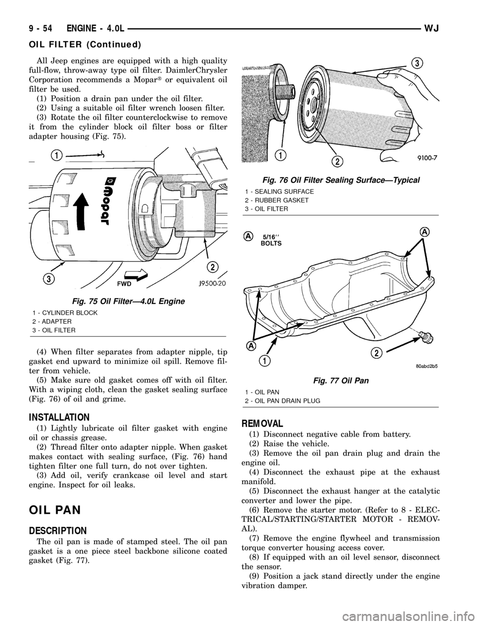
it from the cylinder block oil filter boss or filter
adapter housing (Fig. 75).
(4) When filter separates from adapter nipple, tip
gasket end upward to minimize oil spill. Remove fil-
ter from vehicle.
(5) Make sure old gasket comes off with oil filter.
With a wiping cloth, clean the gasket sealing surface
(Fig. 76) of oil and grime.
INSTALLATION
(1) Lightly lubricate oil filter gasket with engine
oil or chassis grease.
(2) Thread filter onto adapter nipple. When gasket
makes contact with sealing surface, (Fig. 76) hand
tighten filter one full turn, do not over tighten.
(3) Add oil, verify crankcase oil level and start
engine. Inspect for oil leaks.
OIL PAN
DESCRIPTION
The oil pan is made of stamped steel. The oil pan
gasket is a one piece steel backbone silicone coated
gasket (Fig. 77).
REMOVAL
(1) Disconnect negative cable from battery.
(2) Raise the vehicle.
(3) Remove the oil pan drain plug and drain the
engine oil.
(4) Disconnect the exhaust pipe at the exhaust
manifold.
(5) Disconnect the exhaust hanger at the catalytic
converter and lower the pipe.
(6) Remove the starter motor. (Refer to 8 - ELEC-
TRICAL/STARTING/STARTER MOTOR - REMOV-
AL).
(7) Remove the engine flywheel and transmission
torque converter housing access cover.
(8) If equipped with an oil level sensor, disconnect
the sensor.
(9) Position a jack stand directly under the engine
vibration damper.
Fig. 75 Oil FilterÐ4.0L Engine
1 - CYLINDER BLOCK
2 - ADAPTER
3 - OIL FILTER
Fig. 76 Oil Filter Sealing SurfaceÐTypical
1 - SEALING SURFACE
2 - RUBBER GASKET
3 - OIL FILTER
Fig. 77 Oil Pan
1 - OIL PAN
2 - OIL PAN DRAIN PLUG
9 - 54 ENGINE - 4.0LWJ
OIL FILTER (Continued)
Page 1299 of 2199
(9) Lower the engine until it is properly located on
the engine mounts.
(10) Install the through bolts and tighten the nuts.
(11) Lower the jack stand and remove the piece of
wood.
(12) Install the engine flywheel and transmission
torque converter housing access cover.
(13) Install the engine starter motor. (Refer to 8 -
ELECTRICAL/STARTING/STARTER MOTOR -
INSTALLATION).
(14) Connect the exhaust pipe to the hanger and to
the engine exhaust manifold.
(15) Install transmission oil cooling lines (if
equipped) and oxygen sensor wiring supports that
attach to the oil pan studs.
(16) Install the oil pan drain plug (Fig. 81).
Tighten the plug to 34 N´m (25 ft. lbs.) torque.
(17) Lower the vehicle.
(18) Connect negative cable to battery.
(19) Fill the oil pan with engine oil to the specified
level.
WARNING: USE EXTREME CAUTION WHEN THE
ENGINE IS OPERATING. DO NOT STAND IN A
DIRECT LINE WITH THE FAN. DO NOT PUT YOUR
HANDS NEAR THE PULLEYS, BELTS OR FAN. DO
NOT WEAR LOOSE CLOTHING.
(20) Start the engine and inspect for leaks.
ENGINE OIL PRESSURE
SENSOR
DESCRIPTION
The 3±wire, solid-state engine oil pressure sensor
(sending unit) is located in an engine oil pressure
gallery.
OPERATION
The oil pressure sensor uses three circuits. They
are:
²A 5±volt power supply from the Powertrain Con-
trol Module (PCM)
²A sensor ground through the PCM's sensor
return
²A signal to the PCM relating to engine oil pres-
sure
The oil pressure sensor has a 3±wire electrical
function very much like the Manifold Absolute Pres-
sure (MAP) sensor. Meaning different pressures
relate to different output voltages.
A 5±volt supply is sent to the sensor from the PCM
to power up the sensor. The sensor returns a voltage
signal back to the PCM relating to engine oil pres-
sure. This signal is then transferred (bussed) to theinstrument panel on either a CCD or PCI bus circuit
(depending on vehicle line) to operate the oil pressure
gauge and the check gauges lamp. Ground for the
sensor is provided by the PCM through a low-noise
sensor return.
OIL PUMP
REMOVAL
A gear-type oil pump is mounted at the underside
of the cylinder block opposite the No.4 main bearing.
(1) Drain the engine oil.
(2) Remove the oil pan (Refer to 9 - ENGINE/LU-
BRICATION/OIL PAN - REMOVAL).
(3) Remove the pump-to-cylinder block attaching
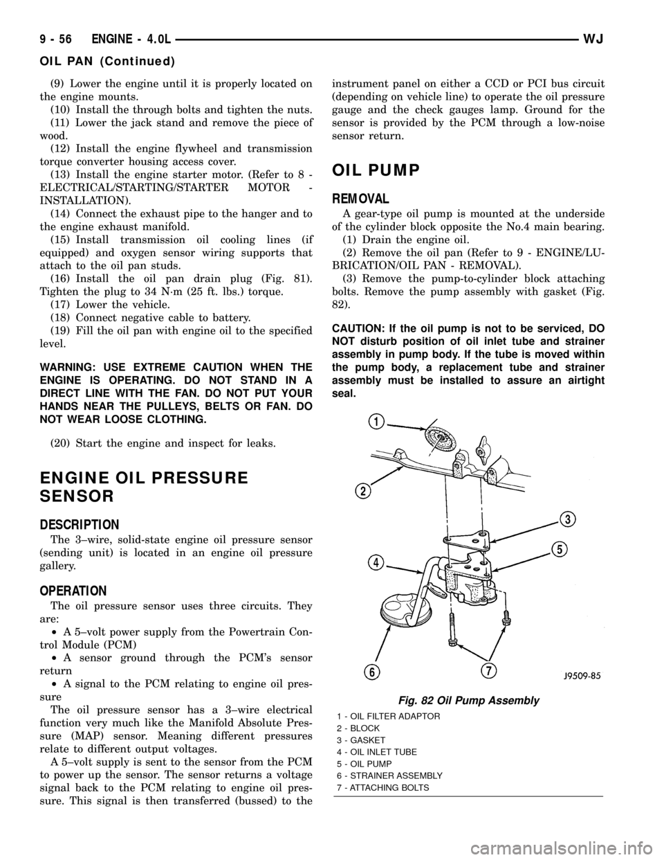
bolts. Remove the pump assembly with gasket (Fig.
82).
CAUTION: If the oil pump is not to be serviced, DO
NOT disturb position of oil inlet tube and strainer
assembly in pump body. If the tube is moved within
the pump body, a replacement tube and strainer
assembly must be installed to assure an airtight
seal.
Fig. 82 Oil Pump Assembly
1 - OIL FILTER ADAPTOR
2 - BLOCK
3 - GASKET
4 - OIL INLET TUBE
5 - OIL PUMP
6 - STRAINER ASSEMBLY
7 - ATTACHING BOLTS
9 - 56 ENGINE - 4.0LWJ
OIL PAN (Continued)
Page 1300 of 2199

INSTALLATION
A gear-type oil pump is mounted at the underside
of the cylinder block opposite the No.4 main bearing.
(1) Install the oil pump on the cylinder block using
a replacement gasket. Tighten the bolts to 23 N´m
(17 ft. lbs.) torque.
(2) Install the oil pan (Refer to 9 - ENGINE/LU-
BRICATION/OIL PAN - INSTALLATION).
(3) Fill the oil pan with oil to the specified level.
INTAKE MANIFOLD
DESCRIPTION
The intake manifold (Fig. 83) is made of cast alu-
minum and uses eleven bolts to mount to the cylin-
der head. This mounting style improves sealing and
reduces the chance of leaks.
DIAGNOSIS AND TESTING - INTAKE
MANIFOLD LEAKAGE
An intake manifold air leak is characterized by
lower than normal manifold vacuum. Also, one or
more cylinders may not be functioning.
WARNING: USE EXTREME CAUTION WHEN THE
ENGINE IS OPERATING. DO NOT STAND IN A
DIRECT LINE WITH THE FAN. DO NOT PUT YOUR
HANDS NEAR THE PULLEYS, BELTS OR THE FAN.
DO NOT WEAR LOOSE CLOTHING.
(1) Start the engine.
(2) Spray a small stream of water at the suspected
leak area.
(3) If a change in RPM is observed the area of the
suspected leak has been found.
(4) Repair as required.
REMOVAL
NOTE: THE ENGINE INTAKE AND EXHAUST MANI-
FOLD MUST BE REMOVED AND INSTALLED
TOGETHER. THE MANIFOLDS USE A COMMON
GASKET AT THE CYLINDER HEAD.
(1) Disconnect the battery negative cable.
(2) Remove air cleaner inlet hose from the resona-
tor assembly.
(3) Remove the air cleaner assembly.
(4) Remove the throttle cable, vehicle speed control
cable (if equipped) and the transmission line pres-
sure cable (Refer to 21 - TRANSMISSION/TRANS-
AXLE/AUTOMATIC - AW4/THROTTLE VALVE
CABLE - REMOVAL).
(5) Disconnect the following electrical connections
and secure their harness out of the way:
²Throttle Position Sensor
²Idle Air Control Motor
²Coolant Temperature Sensor (at thermostat
housing)
²Intake Air Temperature Sensor
²Oxygen Sensor
²Crank Position Sensor
²Six (6) Fuel Injector Connectors
²Manifold Absolute Pressure (MAP) Sensor.
(6) Disconnect HVAC, and Brake Booster vacuum
supply hoses at the intake manifold.
(7) Perform the fuel pressure release procedure.
(Refer to 14 - FUEL SYSTEM/FUEL DELIVERY -
STANDARD PROCEDURE).
(8) Disconnect and remove the fuel system supply
line from the fuel rail assembly.
(9) Remove the accessory drive belt (Refer to 7 -
COOLING/ACCESSORY DRIVE/DRIVE BELTS -
REMOVAL).
(10) Remove the power steering pump from the
intake manifold and set aside.
(11) Raise the vehicle.
(12) Disconnect the exhaust pipes from the engine
exhaust manifolds.
(13) Lower the vehicle.
(14) Remove the intake manifold and exhaust
manifold bolts and manifolds (Fig. 84).
INSTALLATION
If the manifold is being replaced, ensure all the fit-
ting, etc. are transferred to the replacement mani-
fold.
(1) Install a new engine exhaust/intake manifold
gasket over the alignment dowels on the cylinder
head.
(2) Position the engine exhaust manifolds to the
cylinder head. Install fastener Number 3 and finger
tighten at this time (Fig. 84).
Fig. 83 Intake Manifold 4.0L Engine
WJENGINE - 4.0L 9 - 57
OIL PUMP (Continued)
Page 1310 of 2199
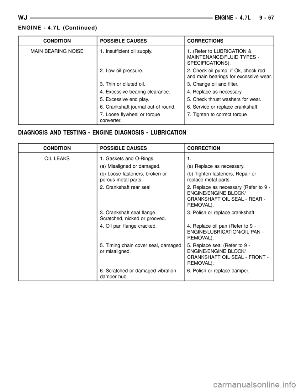
CONDITION POSSIBLE CAUSES CORRECTIONS
MAIN BEARING NOISE 1. Insufficient oil supply. 1. (Refer to LUBRICATION &
MAINTENANCE/FLUID TYPES -
SPECIFICATIONS).
2. Low oil pressure. 2. Check oil pump, if Ok, check rod
and main bearings for excessive wear.
3. Thin or diluted oil. 3. Change oil and filter.
4. Excessive bearing clearance. 4. Replace as necessary.
5. Excessive end play. 5. Check thrust washers for wear.
6. Crankshaft journal out-of round. 6. Service or replace crankshaft.
7. Loose flywheel or torque
converter.7. Tighten to correct torque
DIAGNOSIS AND TESTING - ENGINE DIAGNOSIS - LUBRICATION
CONDITION POSSIBLE CAUSES CORRECTION
OIL LEAKS 1. Gaskets and O-Rings. 1.
(a) Misaligned or damaged. (a) Replace as necessary.
(b) Loose fasteners, broken or
porous metal parts.(b) Tighten fasteners, Repair or
replace metal parts.
2. Crankshaft rear seal 2. Replace as necessary (Refer to 9 -
ENGINE/ENGINE BLOCK/
CRANKSHAFT OIL SEAL - REAR -
REMOVAL).
3. Crankshaft seal flange.
Scratched, nicked or grooved.3. Polish or replace crankshaft.
4. Oil pan flange cracked. 4. Replace oil pan (Refer to 9 -
ENGINE/LUBRICATION/OIL PAN -
REMOVAL).
5. Timing chain cover seal, damaged
or misaligned.5. Replace seal (Refer to 9 -
ENGINE/ENGINE BLOCK/
CRANKSHAFT OIL SEAL - FRONT -
REMOVAL).
6. Scratched or damaged vibration
damper hub.6. Polish or replace damper.
WJENGINE - 4.7L 9 - 67
ENGINE - 4.7L (Continued)