Page 1832 of 2199

(5) Install the rear propeller shaft. (Refer to 3 -
DIFFERENTIAL & DRIVELINE/PROPELLER
SHAFT/PROPELLER SHAFT - INSTALLATION)
(6) Verify proper fluid level.
(7) Lower vehicle.
SHIFT CABLE
REMOVAL
(1) Shift transfer case into NEUTRAL.
(2) Raise vehicle.
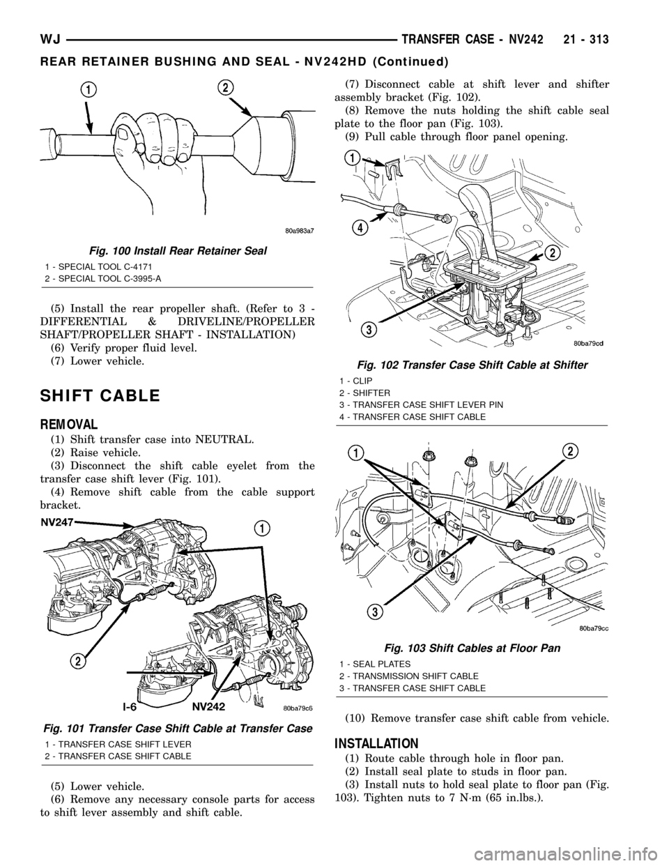
(3) Disconnect the shift cable eyelet from the
transfer case shift lever (Fig. 101).
(4) Remove shift cable from the cable support
bracket.
(5) Lower vehicle.
(6) Remove any necessary console parts for access
to shift lever assembly and shift cable.(7) Disconnect cable at shift lever and shifter
assembly bracket (Fig. 102).
(8) Remove the nuts holding the shift cable seal
plate to the floor pan (Fig. 103).
(9) Pull cable through floor panel opening.
(10) Remove transfer case shift cable from vehicle.
INSTALLATION
(1) Route cable through hole in floor pan.
(2) Install seal plate to studs in floor pan.
(3) Install nuts to hold seal plate to floor pan (Fig.
103). Tighten nuts to 7 N´m (65 in.lbs.).
Fig. 100 Install Rear Retainer Seal
1 - SPECIAL TOOL C-4171
2 - SPECIAL TOOL C-3995-A
Fig. 101 Transfer Case Shift Cable at Transfer Case
1 - TRANSFER CASE SHIFT LEVER
2 - TRANSFER CASE SHIFT CABLE
Fig. 102 Transfer Case Shift Cable at Shifter
1 - CLIP
2 - SHIFTER
3 - TRANSFER CASE SHIFT LEVER PIN
4 - TRANSFER CASE SHIFT CABLE
Fig. 103 Shift Cables at Floor Pan
1 - SEAL PLATES
2 - TRANSMISSION SHIFT CABLE
3 - TRANSFER CASE SHIFT CABLE
WJTRANSFER CASE - NV242 21 - 313
REAR RETAINER BUSHING AND SEAL - NV242HD (Continued)
Page 1836 of 2199

CONDITION POSSIBLE CAUSE CORRECTION
NOISY INÐOR JUMPS OUT OF
4WD LOW RANGE1. Transfer case not completely
engaged in 4WD LOW (possibly
from shift to 4L while rolling)1. Stop vehicle, shift transfer case
to neutral, then shift back to 4WD
LOW
2. Shift linkage loose, binding, or is
misadjusted2. Tighten, lubricate, or repair
linkage as necessary. Adjust linkage
if necessary
3. Range fork cracked, inserts
worn, or fork is binding on shift rail3. Disassemble unit and repair as
necessary
4. Annulus gear or lockplate worn
or damaged4. Disassemble unit and repair as
necessary
LUBRICANT LEAKING FROM
OUTPUT SHAFT SEALS OR FROM
VENT1. Transfer case over filled 1. Drain to correct level
2. Vent closed or restricted 2. Clear or replace vent if necessary
3. Output shaft seals damaged or
installed correctly3. Replace seals. Be sure seal lip
faces interior of case when installed.
Also be sure yoke seal surfaces are
not scored or nicked. Remove
scores and nicks with fine
sandpaper or replace yoke(s) if
necessary.
REMOVAL
(1) Shift transfer case into NEUTRAL.
(2) Raise vehicle.
(3) Remove transfer case drain plug and drain
transfer case lubricant.
(4) Mark front and rear propeller shaft yokes for
alignment reference.
(5) Support transmission with jack stand.
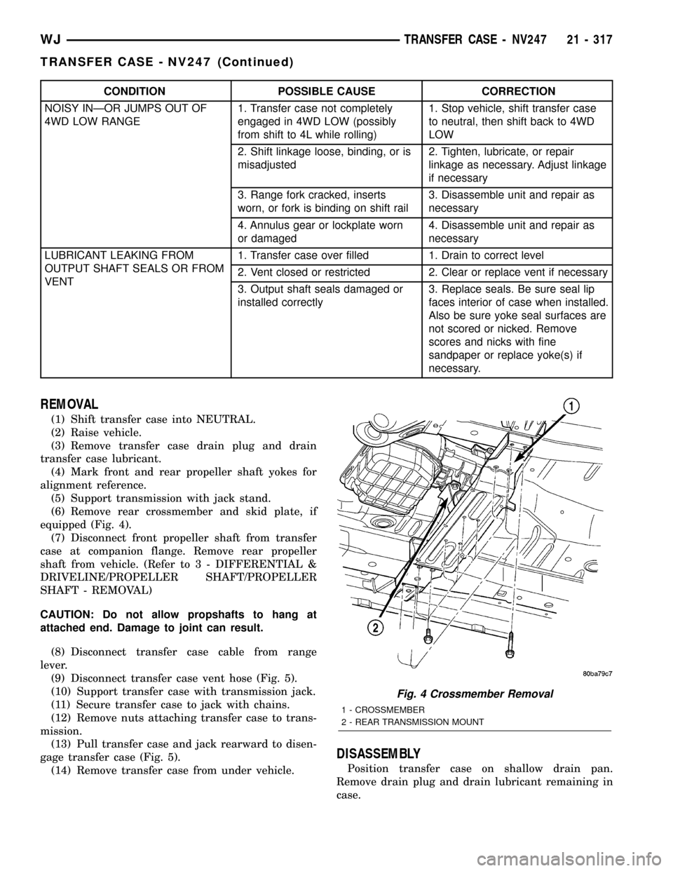
(6) Remove rear crossmember and skid plate, if
equipped (Fig. 4).
(7) Disconnect front propeller shaft from transfer
case at companion flange. Remove rear propeller
shaft from vehicle. (Refer to 3 - DIFFERENTIAL &
DRIVELINE/PROPELLER SHAFT/PROPELLER
SHAFT - REMOVAL)
CAUTION: Do not allow propshafts to hang at
attached end. Damage to joint can result.
(8) Disconnect transfer case cable from range
lever.
(9) Disconnect transfer case vent hose (Fig. 5).
(10) Support transfer case with transmission jack.
(11) Secure transfer case to jack with chains.
(12) Remove nuts attaching transfer case to trans-
mission.
(13) Pull transfer case and jack rearward to disen-
gage transfer case (Fig. 5).
(14) Remove transfer case from under vehicle.
DISASSEMBLY
Position transfer case on shallow drain pan.
Remove drain plug and drain lubricant remaining in
case.
Fig. 4 Crossmember Removal
1 - CROSSMEMBER
2 - REAR TRANSMISSION MOUNT
WJTRANSFER CASE - NV247 21 - 317
TRANSFER CASE - NV247 (Continued)
Page 1855 of 2199

(6) Connect front propeller shaft and install rear
propeller shaft. (Refer to 3 - DIFFERENTIAL &
DRIVELINE/PROPELLER SHAFT/PROPELLER
SHAFT - INSTALLATION)
(7) Fill transfer case with correct fluid. Check
transmission fluid level. Correct as necessary.
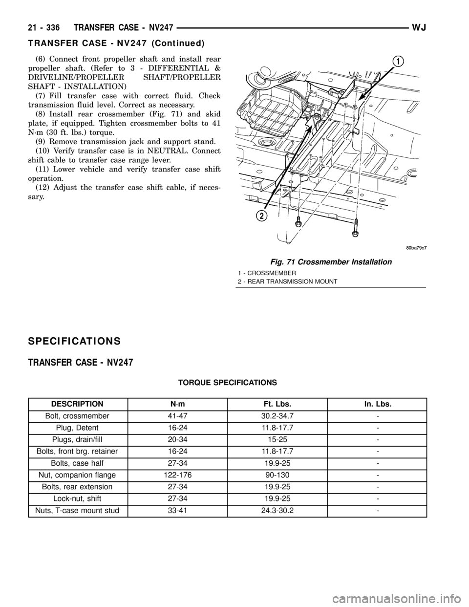
(8) Install rear crossmember (Fig. 71) and skid
plate, if equipped. Tighten crossmember bolts to 41
N´m (30 ft. lbs.) torque.
(9) Remove transmission jack and support stand.
(10) Verify transfer case is in NEUTRAL. Connect
shift cable to transfer case range lever.
(11) Lower vehicle and verify transfer case shift
operation.
(12) Adjust the transfer case shift cable, if neces-
sary.
SPECIFICATIONS
TRANSFER CASE - NV247
TORQUE SPECIFICATIONS
DESCRIPTION N´m Ft. Lbs. In. Lbs.
Bolt, crossmember 41-47 30.2-34.7 -
Plug, Detent 16-24 11.8-17.7 -
Plugs, drain/fill 20-34 15-25 -
Bolts, front brg. retainer 16-24 11.8-17.7 -
Bolts, case half 27-34 19.9-25 -
Nut, companion flange 122-176 90-130 -
Bolts, rear extension 27-34 19.9-25 -
Lock-nut, shift 27-34 19.9-25 -
Nuts, T-case mount stud 33-41 24.3-30.2 -
Fig. 71 Crossmember Installation
1 - CROSSMEMBER
2 - REAR TRANSMISSION MOUNT
21 - 336 TRANSFER CASE - NV247WJ
TRANSFER CASE - NV247 (Continued)
Page 1857 of 2199

FLUID
STANDARD PROCEDURE - FLUID DRAIN/
REFILL
The fill and drain plugs are both in the rear case
(Fig. 72).
(1) Raise vehicle.
(2) Position drain pan under transfer case.
(3) Remove drain and fill plugs and drain lubri-
cant completely.
(4) Install drain plug. Tighten plug to 20-34 N´m
(15-25 ft. lbs.).
(5) Remove drain pan.(6) Fill transfer case to bottom edge of fill plug
opening with MopartTransfer Case Lubricant.
(7) Install and tighten fill plug to 20-34 N´m
(15-25 ft. lbs.).
(8) Lower vehicle.
FRONT OUTPUT SHAFT SEAL
REMOVAL
(1) Raise vehicle on hoist.
(2) Remove front propeller shaft. (Refer to 3 - DIF-
FERENTIAL & DRIVELINE/PROPELLER SHAFT/
PROPELLER SHAFT - REMOVAL)
(3) Remove front output shaft companion shaft.
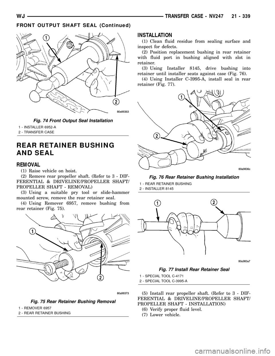
(4) Remove seal from front case with pry tool (Fig.
73).
INSTALLATION
(1) Install new front output seal in front case with
Installer Tool 6952-A as follows:
(a) Place new seal on tool. Garter spring on seal
goes toward interior of case.
(b) Start seal in bore with light taps from ham-
mer (Fig. 74). Once seal is started, continue tap-
ping seal into bore until installer tool seats against
case.
(2) Install companion flange and torque nut to
122-176 N´m (90-130 ft. lbs.).
(3) Install front propeller shaft. (Refer to 3 - DIF-
FERENTIAL & DRIVELINE/PROPELLER SHAFT/
PROPELLER SHAFT - INSTALLATION)
Installer, Bearign - 8128
Installer, Seal - 7884
Fig. 72 Fill/Drain Plug and I.D. Tag Location -
Typical
1 - I.D. TAG
2 - FILL PLUG
3 - DRAIN PLUG
Fig. 73 Remove Front Output Shaft Seal
1 - OUTPUT SHAFT SEAL
2 - PRYBAR
21 - 338 TRANSFER CASE - NV247WJ
TRANSFER CASE - NV247 (Continued)
Page 1858 of 2199

REAR RETAINER BUSHING
AND SEAL
REMOVAL
(1) Raise vehicle on hoist.
(2) Remove rear propeller shaft. (Refer to 3 - DIF-
FERENTIAL & DRIVELINE/PROPELLER SHAFT/
PROPELLER SHAFT - REMOVAL)
(3) Using a suitable pry tool or slide-hammer
mounted screw, remove the rear retainer seal.
(4) Using Remover 6957, remove bushing from
rear retainer (Fig. 75).
INSTALLATION
(1) Clean fluid residue from sealing surface and
inspect for defects.
(2) Position replacement bushing in rear retainer
with fluid port in bushing aligned with slot in
retainer.
(3) Using Installer 8145, drive bushing into
retainer until installer seats against case (Fig. 76).
(4) Using Installer C-3995-A, install seal in rear
retainer (Fig. 77).
(5) Install rear propeller shaft. (Refer to 3 - DIF-
FERENTIAL & DRIVELINE/PROPELLER SHAFT/
PROPELLER SHAFT - INSTALLATION)
(6) Verify proper fluid level.
(7) Lower vehicle.
Fig. 74 Front Output Seal Installation
1 - INSTALLER 6952-A
2 - TRANSFER CASE
Fig. 75 Rear Retainer Bushing Removal
1 - REMOVER 6957
2 - REAR RETAINER BUSHING
Fig. 76 Rear Retainer Bushing Installation
1 - REAR RETAINER BUSHING
2 - INSTALLER 8145
Fig. 77 Install Rear Retainer Seal
1 - SPECIAL TOOL C-4171
2 - SPECIAL TOOL C-3995-A
WJTRANSFER CASE - NV247 21 - 339
FRONT OUTPUT SHAFT SEAL (Continued)
Page:
< prev 1-8 9-16 17-24