2002 JEEP GRAND CHEROKEE drain plug
[x] Cancel search: drain plugPage 278 of 2199

TRANSMISSION
TABLE OF CONTENTS
page page
TRANS COOLER
DESCRIPTION.........................55STANDARD PROCEDURE - FLUSHING
COOLERS AND TUBES.................55
TRANS COOLER
DESCRIPTION
An internal high capacity/high efficiency cooler is
used on all vehicles these coolers are an oil-to-coolant
type which consists of plates mounted in the radiator
outlet tank (Fig. 36). Because the internal oil cooler
is so efficient, no auxiliary oil cooler is offered The
cooler is not servicable seperatly from the radiator.
STANDARD PROCEDURE - FLUSHING
COOLERS AND TUBES
When a transmission failure has contaminated the
fluid, the oil cooler(s) must be flushed. The torque
converter must also be replaced. This will insure that
metal particles or sludged oil are not later trans-
ferred back into the reconditioned (or replaced) trans-
mission.
The only recommended procedure for flushing cool-
ers and lines is to use Tool 6906-B Cooler Flusher.
WARNING: WEAR PROTECTIVE EYEWEAR THAT
MEETS THE REQUIREMENTS OF OSHA AND ANSI
Z87.1±1968. WEAR STANDARD INDUSTRIAL RUB-
BER GLOVES.
KEEP LIGHTED CIGARETTES, SPARKS, FLAMES,
AND OTHER IGNITION SOURCES AWAY FROM THE
AREA TO PREVENT THE IGNITION OF COMBUSTI-
BLE LIQUIDS AND GASES. KEEP A CLASS (B) FIRE
EXTINGUISHER IN THE AREA WHERE THE
FLUSHER WILL BE USED.
KEEP THE AREA WELL VENTILATED.
DO NOT LET FLUSHING SOLVENT COME IN CON-
TACT WITH YOUR EYES OR SKIN: IF EYE CONTAM-
INATION OCCURS, FLUSH EYES WITH WATER FOR
15 TO 20 SECONDS. REMOVE CONTAMINATED
CLOTHING AND WASH AFFECTED SKIN WITH
SOAP AND WATER. SEEK MEDICAL ATTENTION.
(1) Remove cover plate filler plug on Tool 6906-B.
Fill reservoir 1/2 to 3/4 full of fresh flushing solution.
Flushing solvents are petroleum based solutions gen-
erally used to clean automatic transmission compo-
nents.DO NOTuse solvents containing acids, water,
gasoline, or any other corrosive liquids.(2) Reinstall filler plug on Tool 6906-B.
(3) Verify pump power switch is turned OFF. Con-
nect red alligator clip to positive (+) battery post.
Connect black (-) alligator clip to a good ground.
(4) Disconnect the cooler lines at the transmission.
NOTE: When flushing transmission cooler and
lines, ALWAYS reverse flush.
NOTE: The converter drainback valve must be
removed and an appropriate replacement hose
installed to bridge the space between the transmis-
sion cooler line and the cooler fitting. Failure to
remove the drainback valve will prevent reverse
flushing the system. A suitable replacement hose
can be found in the adapter kit supplied with the
flushing tool.
(5) Connect the BLUE pressure line to the OUT-
LET (From) cooler line.
(6) Connect the CLEAR return line to the INLET
(To) cooler line
(7) Turn pump ON for two to three minutes to
flush cooler(s) and lines.
(8) Turn pump OFF.
(9) Disconnect CLEAR suction line from reservoir
at cover plate. Disconnect CLEAR return line at
cover plate, and place it in a drain pan.
(10) Turn pump ON for 30 seconds to purge flush-
ing solution from cooler and lines. Turn pump OFF.
(11) Place CLEAR suction line into a one quart
container of MopartATF +4, type 9602, Automatic
Transmission Fluid.
(12) Turn pump ON until all transmission fluid is
removed from the one quart container and lines. This
purges any residual cleaning solvent from the trans-
mission cooler and lines. Turn pump OFF.
(13) Disconnect alligator clips from battery. Recon-
nect flusher lines to cover plate, and remove flushing
adapters from cooler lines.
WJTRANSMISSION 7 - 55
Page 615 of 2199

switch, check for battery voltage at the washer pump
switch sense circuit cavity of the instrument panel
wire harness connector (Connector C2) for the BCM.
If OK, use a DRBIIItscan tool to diagnose the BCM.
Refer to the appropriate diagnostic information. If
not OK, repair the open washer pump switch sense
circuit between the right (wiper) multi-function
switch and the BCM as required.
CLEANING - FRONT WIPER & WASHER
SYSTEM
WIPER SYSTEM
The squeegees of wiper blades exposed to the ele-
ments for a long time tend to lose their wiping effec-
tiveness. Periodic cleaning of the squeegees is
suggested to remove any deposits of salt or road film.
The wiper blades, arms, and windshield glass should
only be cleaned using a sponge or soft cloth and
windshield washer fluid, a mild detergent, or a non-
abrasive cleaner. If the wiper blades continue to
leave streaks, smears, hazing, or beading on the
glass after thorough cleaning of the squeegees and
the glass, the entire wiper blade assembly must be
replaced.
CAUTION: Protect the rubber squeegees of the
wiper blades from any petroleum-based cleaners,
solvents, or contaminants. These products can rap-
idly deteriorate the rubber squeegees.
WASHER SYSTEM
If the washer system is contaminated with foreign
material, drain the washer reservoir by removing the
front washer pump/motor from the reservoir. Clean
foreign material from the inside of the washer reser-
voir using clean washer fluid, a mild detergent, or a
non-abrasive cleaner. Flush foreign material from the
washer system plumbing by first disconnecting the
washer hoses from the washer nozzles, then running
the washer pump/motor to run clean washer fluid or
water through the system. Plugged or restricted
washer nozzles should be carefully back-flushed
using compressed air. If the washer nozzle obstruc-
tion cannot be cleared, replace the washer nozzle.
CAUTION: Never introduce petroleum-based clean-
ers, solvents, or contaminants into the washer sys-
tem. These products can rapidly deteriorate the
rubber seals and hoses of the washer system, as
well as the rubber squeegees of the wiper blades.
CAUTION: Never use compressed air to flush the
washer system plumbing. Compressed air pres-
sures are too great for the washer system plumbingcomponents and will result in further system dam-
age. Never use sharp instruments to clear a
plugged washer nozzle or damage to the nozzle ori-
fice and improper nozzle spray patterns will result.
INSPECTION - FRONT WIPER & WASHER
SYSTEM
WIPER SYSTEM
The front wiper blades and wiper arms should be
inspected periodically, not just when wiper perfor-
mance problems are experienced. This inspection
should include the following points:
(1) Inspect the wiper arms for any indications of
damage, or contamination. If the wiper arms are con-
taminated with any foreign material, clean them as
required. (Refer to 8 - ELECTRICAL/FRONT WIP-
ERS/WASHERS - CLEANING). If a wiper arm is
damaged or corrosion is evident, replace the wiper
arm with a new unit. Do not attempt to repair a
wiper arm that is damaged or corroded.
(2) Carefully lift the wiper blade off of the glass.
Note the action of the wiper arm hinge. The wiper
arm should pivot freely at the hinge, but with no lat-
eral looseness evident. If there is any binding evident
in the wiper arm hinge, or there is evident lateral
play in the wiper arm hinge, replace the wiper arm.
CAUTION: Do not allow the wiper arm to spring
back against the glass without the wiper blade in
place or the glass may be damaged.
(3) Once proper hinge action of the wiper arm is
confirmed, check the hinge for proper spring tension.
Remove the wiper blade from the wiper arm. Either
place a small postal scale between the blade end of
the wiper arm and the glass, or carefully lift the
blade end of the arm away from the glass using a
small fish scale. Compare the scale readings between
the right and left wiper arms. Replace a wiper arm if
it has comparatively lower spring tension, as evi-
denced by a lower scale reading.
(4) Inspect the wiper blades and squeegees for any
indications of damage, contamination, or rubber dete-
rioration (Fig. 2). If the wiper blades or squeegees
are contaminated with any foreign material, clean
them and the glass as required. (Refer to 8 - ELEC-
TRICAL/FRONT WIPERS/WASHERS - CLEANING).
After cleaning the wiper blade and the glass, if the
wiper blade still fails to clear the glass without
smearing, streaking, chattering, hazing, or beading,
replace the wiper blade. Also, if a wiper blade is
damaged or the squeegee rubber is damaged or dete-
riorated, replace the wiper blade with a new unit. Do
not attempt to repair a wiper blade that is damaged.
8R - 8 FRONT WIPERS/WASHERSWJ
FRONT WIPERS/WASHERS (Continued)
Page 644 of 2199

(2) Turn the ignition switch to the Off position.
Disconnect and isolate the battery negative cable.
Disconnect the left headlamp and dash wire harness
connector for the rear washer pump/motor unit from
the pump/motor unit connector receptacle. Check for
continuity between the ground circuit cavity of the
left headlamp and dash wire harness connector for
the rear washer pump/motor unit and a good ground.
There should be continuity. If OK, go to Step 3. If not
OK, repair the open ground circuit to ground (G106)
as required.
(3) Reconnect the battery negative cable. Turn the
ignition switch to the On position. Push the right
multi-function switch control stalk toward the instru-
ment panel to actuate the rear washer switch. With
the rear washer switch actuated, check for battery
voltage at the rear washer switch output circuit cav-
ity of the left headlamp and dash wire harness con-
nector for the rear washer pump/motor unit. If OK,
replace the faulty rear washer pump/motor unit. If
not OK, repair the open rear washer switch output
circuit between the rear washer pump/motor unit
and the right multi-function switch as required.
CLEANING - REAR WIPER & WASHER SYSTEM
WIPER SYSTEM
The squeegee of a wiper blade exposed to the ele-
ments for a long time tends to lose its wiping effec-
tiveness. Periodic cleaning of the squeegee is
suggested to remove any deposits of salt or road film.
The wiper blade, arm, and liftgate glass should only
be cleaned using a sponge or soft cloth and wind-
shield washer fluid, a mild detergent, or a non-abra-
sive cleaner. If the wiper blade continues to leave
streaks, smears, hazing, or beading on the glass after
thorough cleaning of the squeegees and the glass, the
entire wiper blade assembly must be replaced.
CAUTION: Protect the rubber squeegee of the wiper
blade from any petroleum-based cleaners, solvents,
or contaminants. These products can rapidly deteri-
orate the rubber squeegee.
WASHER SYSTEM
If the washer system is contaminated with foreign
material, drain the washer reservoir by removing the
front washer pump/motor from the reservoir. Clean
foreign material from the inside of the washer reser-
voir using clean washer fluid, a mild detergent, or a
non-abrasive cleaner. Flush foreign material from the
washer system plumbing by first disconnecting the
washer hose from the washer nozzle, then running
the washer pump/motor to run clean washer fluid or
water through the system. A plugged or restricted
washer nozzle should be carefully back-flushed usingcompressed air. If the washer nozzle obstruction can-
not be cleared, replace the washer nozzle.
CAUTION: Never introduce petroleum-based clean-
ers, solvents, or contaminants into the washer sys-
tem. These products can rapidly deteriorate the
rubber seals and hoses of the washer system, as
well as the rubber squeegee of the wiper blade.
CAUTION: Never use compressed air to flush the
washer system plumbing. Compressed air pres-
sures are too great for the washer system plumbing
components and will result in further system dam-
age. Never use sharp instruments to clear a
plugged washer nozzle or damage to the nozzle ori-
fice and improper nozzle spray patterns will result.
INSPECTION - REAR WIPER & WASHER
SYSTEM
WIPER SYSTEM
The rear wiper blade and wiper arm should be
inspected periodically, not just when wiper perfor-
mance problems are experienced. This inspection
should include the following points:
(1) Inspect the wiper arm for any indications of
damage, or contamination. If the wiper arm is con-
taminated with any foreign material, clean as
required. (Refer to 8 - ELECTRICAL/REAR WIPERS/
WASHERS - CLEANING). If a wiper arm is damaged
or corrosion is evident, replace the wiper arm with a
new unit. Do not attempt to repair a wiper arm that
is damaged or corroded.
(2) Carefully lift the wiper arm off of the ramp.
Note the action of the wiper arm hinge. The wiper
arm should pivot freely at the hinge, but with no lat-
eral looseness evident. If there is any binding evident
in the wiper arm hinge, or there is evident lateral
play in the wiper arm hinge, replace the wiper arm.
CAUTION: Do not allow the wiper arm to spring
back against the glass without the wiper blade in
place or the glass may be damaged.
(3) Once proper hinge action of the wiper arm is
confirmed, check the hinge for proper spring tension.
The spring tension of the wiper arm should be suffi-
cient to cause the rubber squeegee to conform to the
curvature of the glass. Replace a wiper arm if it has
low or no spring tension.
(4) Inspect the wiper blade and squeegee for any
indications of damage, contamination, or rubber dete-
rioration (Fig. 1). If the wiper blade or squeegee is
contaminated with any foreign material, clean them
and the glass as required. (Refer to 8 - ELECTRI-
WJREAR WIPERS/WASHERS 8R - 37
REAR WIPERS/WASHERS (Continued)
Page 1253 of 2199

FORM-IN-PLACE GASKET AND SEALER
APPLICATION
Assembling parts using a form-in-place gasket
requires care but it's easier then using precut gaskets.
MopartGasket Maker material should be applied
sparingly 1 mm (0.040 in.) diameter or less of sealant
to one gasket surface. Be certain the material sur-
rounds each mounting hole. Excess material can eas-
ily be wiped off. Components should be torqued in
place within 15 minutes. The use of a locating dowel
is recommended during assembly to prevent smear-
ing material off the location.
MopartEngine RTV GEN II or ATF RTV gasket
material should be applied in a continuous bead
approximately 3 mm (0.120 in.) in diameter. All
mounting holes must be circled. For corner sealing, a
3.17 or 6.35 mm (1/8 or 1/4 in.) drop is placed in the
center of the gasket contact area. Uncured sealant
may be removed with a shop towel. Components
should be torqued in place while the sealant is still
wet to the touch (within 10 minutes). The usage of a
locating dowel is recommended during assembly to
prevent smearing material off the location.
MopartGasket Sealant in an aerosol can should be
applied using a thin, even coat sprayed completely
over both surfaces to be joined, and both sides of a
gasket. Then proceed with assembly. Material in a
can w/applicator can be brushed on evenly over the
sealing surfaces. Material in an aerosol can should be
used on engines with multi-layer steel gaskets.
STANDARD PROCEDURE - REPAIR DAMAGED
OR WORN THREADS
CAUTION: Be sure that the tapped holes maintain
the original center line.
Damaged or worn threads can be repaired. Essen-
tially, this repair consists of:
²Drilling out worn or damaged threads.
²Tapping the hole with a special Heli-Coil Tap, or
equivalent.
²Installing an insert into the tapped hole to bring
the hole back to its original thread size.
STANDARD PROCEDUREÐHYDROSTATIC LOCK
CAUTION: DO NOT use the starter motor to rotate
the crankshaft. Severe damage could occur.
When an engine is suspected of hydrostatic lock
(regardless of what caused the problem), follow the
steps below.
(1) Perform the Fuel Pressure Release Procedure
(Refer to 14 - FUEL SYSTEM/FUEL DELIVERY -
STANDARD PROCEDURE).(2) Disconnect the negative cable(s) from the bat-
tery.
(3) Inspect air cleaner, induction system, and
intake manifold to ensure system is dry and clear of
foreign material.
(4) Place a shop towel around the spark plugs to
catch any fluid that may possibly be under pressure
in the cylinder head. Remove the spark plugs.
(5) With all spark plugs removed, rotate the crank-
shaft using a breaker bar and socket.
(6) Identify the fluid in the cylinders (coolant, fuel,
oil, etc.).
(7) Be sure all fluid has been removed from the
cylinders.
(8) Repair engine or components as necessary to
prevent this problem from occurring again.
(9) Squirt a small amount of engine oil into the
cylinders to lubricate the walls. This will prevent
damage on restart.
(10) Install new spark plugs. Tighten the spark
plugs to 41 N´m (30 ft. lbs.) torque.
(11) Drain engine oil. Remove and discard the oil
filter.
(12) Install the drain plug. Tighten the plug to 34
N´m (25 ft. lbs.) torque.
(13) Install a new oil filter.
(14) Fill engine crankcase with the specified
amount and grade of oil. (Refer to LUBRICATION &
MAINTENANCE - SPECIFICATIONS).
(15) Connect the negative cable(s) to the battery.
(16) Start the engine and check for any leaks.
STANDARD PROCEDURE - CYLINDER BORE
HONING
Before honing, stuff plenty of clean shop towels
under the bores and over the crankshaft to keep
abrasive materials from entering the crankshaft
area.
(1)
Used carefully, the Cylinder Bore Sizing Hone
C-823, equipped with 220 grit stones, is the best tool
for this job. In addition to deglazing, it will reduce
taper and out-of-round, as well as removing light scuff-
ing, scoring and scratches. Usually, a few strokes will
clean up a bore and maintain the required limits.
CAUTION: DO NOT use rigid type hones to remove
cylinder wall glaze.
(2) Deglazing of the cylinder walls may be done if
the cylinder bore is straight and round. Use a cylin-
der surfacing hone, Honing Tool C-3501, equipped
with 280 grit stones (C-3501-3810). about 20-60
strokes, depending on the bore condition, will be suf-
ficient to provide a satisfactory surface. Using honing
oil C-3501-3880, or a light honing oil, available from
major oil distributors.
9 - 10 ENGINE - 4.0LWJ
ENGINE - 4.0L (Continued)
Page 1254 of 2199

CAUTION: DO NOT use engine or transmission oil,
mineral spirits, or kerosene.
(3) Honing should be done by moving the hone up
and down fast enough to get a crosshatch pattern.
The hone marks should INTERSECT at 40É to 60É
for proper seating of rings (Fig. 3).
(4) A controlled hone motor speed between 200 and
300 RPM is necessary to obtain the proper cross-
hatch angle. The number of up and down strokes per
minute can be regulated to get the desired 40É to 60É
angle. Faster up and down strokes increase the cross-
hatch angle.
(5) After honing, it is necessary that the block be
cleaned to remove all traces of abrasive. Use a brush
to wash parts with a solution of hot water and deter-
gent. Dry parts thoroughly. Use a clean, white, lint-
free cloth to check that the bore is clean. Oil the
bores after cleaning to prevent rusting.
STANDARD PROCEDURE - ENGINE CORE AND
OIL GALLERY PLUGS
Using a blunt tool such as a drift and a hammer,
strike the bottom edge of the cup plug. With the cup
plug rotated, grasp firmly with pliers or other suit-
able tool and remove plug (Fig. 4).CAUTION: Do not drive cup plug into the casting as
restricted cooling can result and cause serious
engine problems.
Thoroughly clean inside of cup plug hole in cylin-
der block or head. Be sure to remove old sealer.
Lightly coat inside of cup plug hole with Mopart
Stud and Bearing Mount. Make certain the new plug
is cleaned of all oil or grease. Using proper drive
plug, drive plug into hole so that the sharp edge of
the plug is at least 0.5 mm (0.020 in.) inside the
lead-in chamfer.
It is not necessary to wait for curing of the sealant.
The cooling system can be refilled and the vehicle
placed in service immediately.
REMOVAL
(1) Disconnect the battery negative cable.
(2) Mark the hinge locations on the hood panel for
alignment reference during installation. Remove the
engine compartment lamp. Remove the hood.
(3) Remove the radiator drain cock and radiator
cap to drain the coolant. DO NOT waste usable cool-
ant. If the solution is clean, drain the coolant into a
clean container for reuse.
(4) Remove the upper radiator hose and coolant
recovery hose.
(5) Remove the lower radiator hose.
(6) Remove upper radiator support retaining bolts
and remove radiator support.
Fig. 3 Cylinder Bore Crosshatch Pattern
1 - CROSSHATCH PATTERN
2 - INTERSECT ANGLE
Fig. 4 Core Hole Plug Removal
1 - CYLINDER BLOCK
2 - REMOVE PLUG WITH PLIERS
3 - STRIKE HERE WITH HAMMER
4 - DRIFT PUNCH
5 - CUP PLUG
WJENGINE - 4.0L 9 - 11
ENGINE - 4.0L (Continued)
Page 1260 of 2199
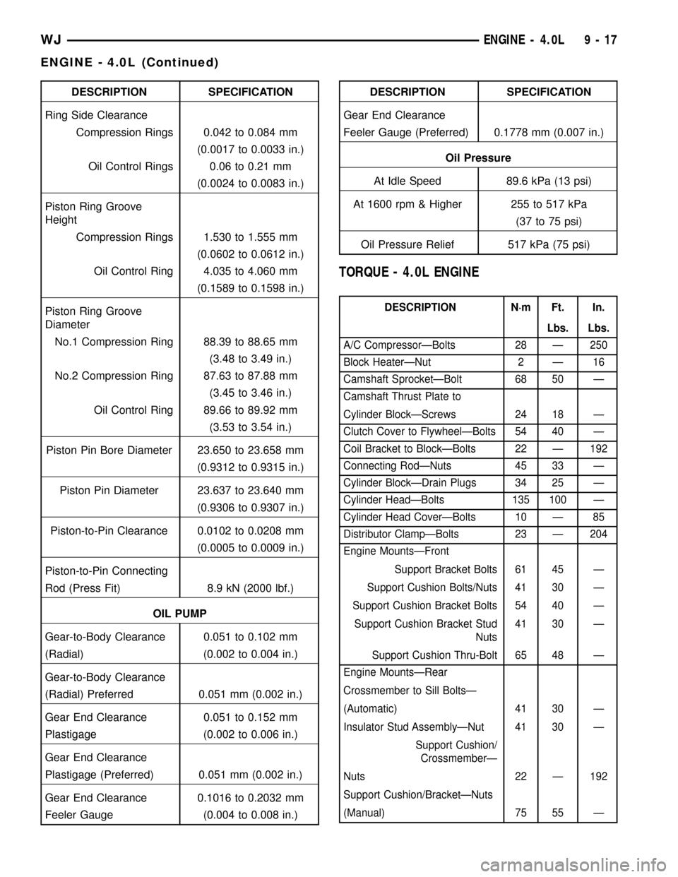
DESCRIPTION SPECIFICATION
Ring Side Clearance
Compression Rings 0.042 to 0.084 mm
(0.0017 to 0.0033 in.)
Oil Control Rings 0.06 to 0.21 mm
(0.0024 to 0.0083 in.)
Piston Ring Groove
Height
Compression Rings 1.530 to 1.555 mm
(0.0602 to 0.0612 in.)
Oil Control Ring 4.035 to 4.060 mm
(0.1589 to 0.1598 in.)
Piston Ring Groove
Diameter
No.1 Compression Ring 88.39 to 88.65 mm
(3.48 to 3.49 in.)
No.2 Compression Ring 87.63 to 87.88 mm
(3.45 to 3.46 in.)
Oil Control Ring 89.66 to 89.92 mm
(3.53 to 3.54 in.)
Piston Pin Bore Diameter 23.650 to 23.658 mm
(0.9312 to 0.9315 in.)
Piston Pin Diameter 23.637 to 23.640 mm
(0.9306 to 0.9307 in.)
Piston-to-Pin Clearance 0.0102 to 0.0208 mm
(0.0005 to 0.0009 in.)
Piston-to-Pin Connecting
Rod (Press Fit) 8.9 kN (2000 lbf.)
OIL PUMP
Gear-to-Body Clearance 0.051 to 0.102 mm
(Radial) (0.002 to 0.004 in.)
Gear-to-Body Clearance
(Radial) Preferred 0.051 mm (0.002 in.)
Gear End Clearance 0.051 to 0.152 mm
Plastigage (0.002 to 0.006 in.)
Gear End Clearance
Plastigage (Preferred) 0.051 mm (0.002 in.)
Gear End Clearance 0.1016 to 0.2032 mm
Feeler Gauge (0.004 to 0.008 in.)DESCRIPTION SPECIFICATION
Gear End Clearance
Feeler Gauge (Preferred) 0.1778 mm (0.007 in.)
Oil Pressure
At Idle Speed 89.6 kPa (13 psi)
At 1600 rpm & Higher 255 to 517 kPa
(37 to 75 psi)
Oil Pressure Relief 517 kPa (75 psi)
TORQUE - 4.0L ENGINE
DESCRIPTION N´m Ft. In.
Lbs. Lbs.
A/C CompressorÐBolts 28 Ð 250
Block HeaterÐNut 2 Ð 16
Camshaft SprocketÐBolt 68 50 Ð
Camshaft Thrust Plate to
Cylinder BlockÐScrews 24 18 Ð
Clutch Cover to FlywheelÐBolts 54 40 Ð
Coil Bracket to BlockÐBolts 22 Ð 192
Connecting RodÐNuts 45 33 Ð
Cylinder BlockÐDrain Plugs 34 25 Ð
Cylinder HeadÐBolts 135 100 Ð
Cylinder Head CoverÐBolts 10 Ð 85
Distributor ClampÐBolts 23 Ð 204
Engine MountsÐFront
Support Bracket Bolts 61 45 Ð
Support Cushion Bolts/Nuts 41 30 Ð
Support Cushion Bracket Bolts 54 40 Ð
Support Cushion Bracket Stud
Nuts41 30 Ð
Support Cushion Thru-Bolt 65 48 Ð
Engine MountsÐRear
Crossmember to Sill BoltsÐ
(Automatic) 41 30 Ð
Insulator Stud AssemblyÐNut 41 30 Ð
Support Cushion/
CrossmemberÐ
Nuts 22 Ð 192
Support Cushion/BracketÐNuts
(Manual) 75 55 Ð
WJENGINE - 4.0L 9 - 17
ENGINE - 4.0L (Continued)
Page 1261 of 2199
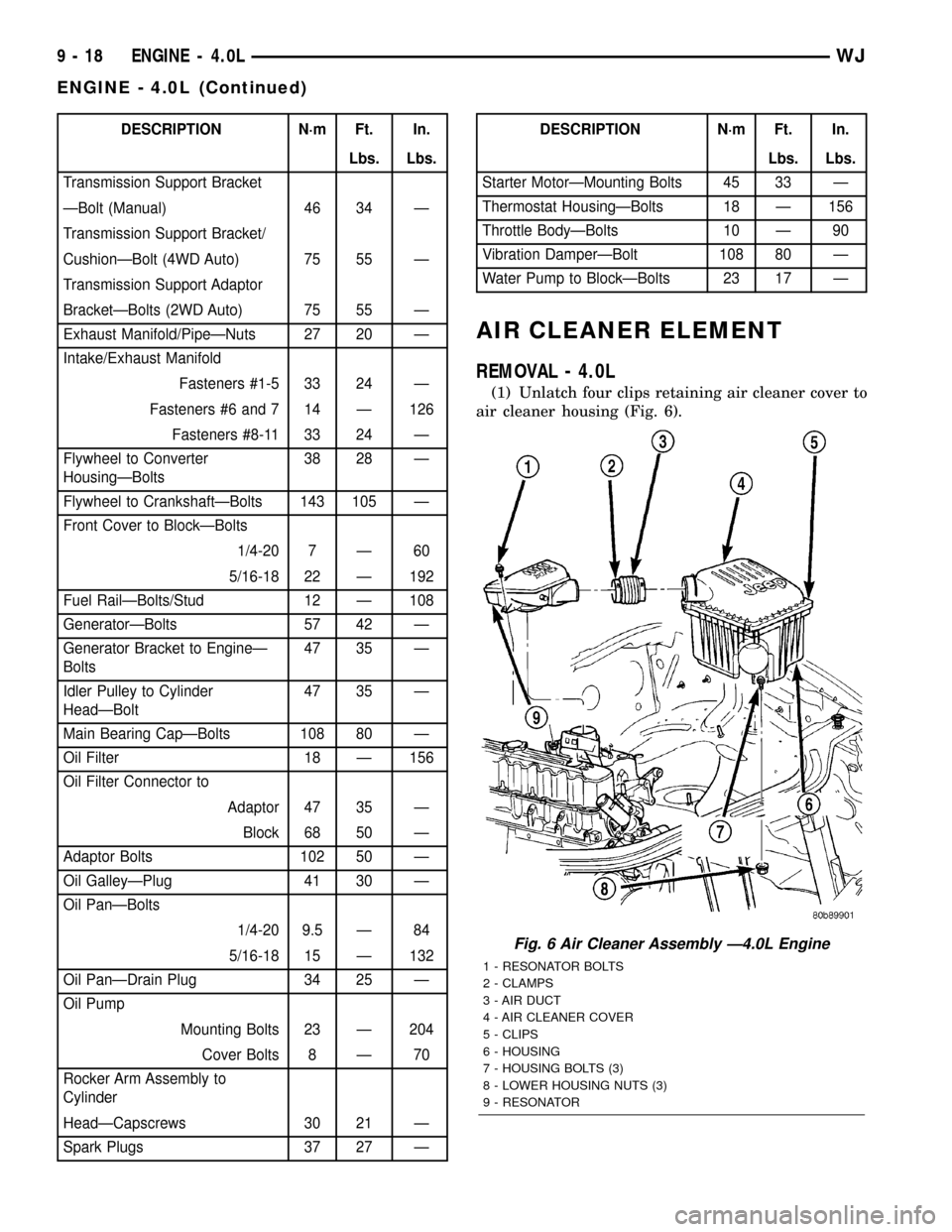
DESCRIPTION N´m Ft. In.
Lbs. Lbs.
Transmission Support Bracket
ÐBolt (Manual) 46 34 Ð
Transmission Support Bracket/
CushionÐBolt (4WD Auto) 75 55 Ð
Transmission Support Adaptor
BracketÐBolts (2WD Auto) 75 55 Ð
Exhaust Manifold/PipeÐNuts 27 20 Ð
Intake/Exhaust Manifold
Fasteners #1-5 33 24 Ð
Fasteners #6 and 7 14 Ð 126
Fasteners #8-11 33 24 Ð
Flywheel to Converter
HousingÐBolts38 28 Ð
Flywheel to CrankshaftÐBolts 143 105 Ð
Front Cover to BlockÐBolts
1/4-20 7 Ð 60
5/16-18 22 Ð 192
Fuel RailÐBolts/Stud 12 Ð 108
GeneratorÐBolts 57 42 Ð
Generator Bracket to EngineÐ
Bolts47 35 Ð
Idler Pulley to Cylinder
HeadÐBolt47 35 Ð
Main Bearing CapÐBolts 108 80 Ð
Oil Filter 18 Ð 156
Oil Filter Connector to
Adaptor 47 35 Ð
Block 68 50 Ð
Adaptor Bolts 102 50 Ð
Oil GalleyÐPlug 41 30 Ð
Oil PanÐBolts
1/4-20 9.5 Ð 84
5/16-18 15 Ð 132
Oil PanÐDrain Plug 34 25 Ð
Oil Pump
Mounting Bolts 23 Ð 204
Cover Bolts 8 Ð 70
Rocker Arm Assembly to
Cylinder
HeadÐCapscrews 30 21 Ð
Spark Plugs 37 27 ÐDESCRIPTION N´m Ft. In.
Lbs. Lbs.
Starter MotorÐMounting Bolts 45 33 Ð
Thermostat HousingÐBolts 18 Ð 156
Throttle BodyÐBolts 10 Ð 90
Vibration DamperÐBolt 108 80 Ð
Water Pump to BlockÐBolts 23 17 Ð
AIR CLEANER ELEMENT
REMOVAL - 4.0L
(1) Unlatch four clips retaining air cleaner cover to
air cleaner housing (Fig. 6).
Fig. 6 Air Cleaner Assembly Ð4.0L Engine
1 - RESONATOR BOLTS
2 - CLAMPS
3 - AIR DUCT
4 - AIR CLEANER COVER
5 - CLIPS
6 - HOUSING
7 - HOUSING BOLTS (3)
8 - LOWER HOUSING NUTS (3)
9 - RESONATOR
9 - 18 ENGINE - 4.0LWJ
ENGINE - 4.0L (Continued)
Page 1262 of 2199

(2) Lift cover up and position to the side.
(3) Remove air cleaner element.
INSTALLATION - 4.0L
(1) Clean inside of air cleaner housing before
installing new element.
(2) Install air cleaner element into housing.
(3) Latch clips and clamp cover down to secure. Be
sure air cleaner cover is properly seated to air
cleaner housing.
AIR CLEANER HOUSING
REMOVAL - 4.0L
(1) Disconnect air cleaner cover-to-air duct clamp
(Fig. 6).
(2) Disconnect air duct at housing.
(3)Each of the 3 air cleaner housing mount-
ing bolts is attached with 2 nuts (an upper nut
and lower nut). DO NOT REMOVE BOLTS. To
prevent stripping bolts, only remove lower
nuts. The lower housing nuts are located under
left front inner fender (Fig. 6).
(a) To gain access to lower nuts, raise vehicle.
(b) Remove clips retaining rubber inner fender
shield.
(c) Pry back shield enough to gain access to
lower nuts.
(d) Remove 3 nuts.
(e) Remove air cleaner assembly from vehicle.
(4) If resonator is to be removed, disconnect
breather tube at resonator, disconnect air duct clamp
at resonator (Fig. 6)and remove 1 resonator mount-
ing bolt. Remove resonator from throttle body by
loosening clamp (Fig. 7).
INSTALLATION - 4.0L
(1) Position air cleaner assembly to body and
install 3 nuts. Tighten nuts to 10 N´m (93 in. lbs.)
torque.To prevent excessive vibration transmit-
ted through housing, the nuts must be properly
torqued. Do not overtighten nuts.
(2) If resonator was removed: Install resonator and
bolts. Tighten bolts to 4 N´m (35 in. lbs.) torque.
Tighten clamp at throttle body to 4 N´m (35 in. lbs.)
torque.
(3) Position fender liner and install clips.
(4) Connect air duct at housing (Fig. 6).
(5) Tighten air duct clamp.
CYLINDER HEAD
DESCRIPTION
The cylinder head is made of cast iron containing
twelve valves made of chrome plated heat resistant
steel, valve stem seals, springs, retainers and keep-
ers. The cylinder head and valve seats can be resur-
faced for service purposes.
The valve guides are integral to the cylinder head,
They are not replaceable. However, they are service-
able.
The cylinder head uses dual quench-type design
combustion chambers which cause turbulence in the
cylinders allowing faster burning of the air/fuel mix-
ture, resulting in better fuel economy (Fig. 8).
REMOVAL
NOTE: This procedure can be done with the engine
in or out of the vehicle.
(1) Disconnect the battery negative cable.
WARNING: DO NOT REMOVE THE CYLINDER
BLOCK DRAIN PLUGS OR LOOSEN THE RADIATOR
DRAIN COCK WITH THE SYSTEM HOT AND PRES-
SURIZED BECAUSE SERIOUS BURNS FROM THE
COOLANT CAN OCCUR.
Fig. 7 RESONATOR CLAMP - 4.0L
1 - RESONATOR
2 - AIR DUCT
3 - CLAMP
WJENGINE - 4.0L 9 - 19
AIR CLEANER ELEMENT (Continued)