2002 JEEP GRAND CHEROKEE Plugs
[x] Cancel search: PlugsPage 450 of 2199

ing the system voltage is high (system voltage is
about sixteen volts or higher), the gauge needle is
moved to the relative voltage position in the red zone
of the gauge scale and the check gauges indicator is
illuminated. The gauge needle remains in the red
zone and the check gauges indicator remains illumi-
nated until the cluster receives a message from the
PCM indicating there is no high system voltage con-
dition (system voltage is below about sixteen volts,
but higher than about eleven volts).
²Communication Error- If the cluster fails to
receive a system voltage message, it will hold the
gauge needle at the last indication for about twelve
seconds, until a new message is received, or until the
ignition switch is turned to the Off position, which-
ever occurs first. After twelve seconds, the cluster
will return the gauge needle to the low end of the
gauge scale.
²Actuator Test- Each time the cluster is put
through the actuator test, the gauge needle will be
swept across the entire gauge scale and back to con-
firm the functionality of the gauge and the cluster
control circuitry.
The PCM continually monitors the system voltage
to control the generator output. The PCM then sends
the proper system voltage messages to the instru-
ment cluster. For further diagnosis of the voltage
gauge or the instrument cluster circuitry that con-
trols the gauge, (Refer to 8 - ELECTRICAL/INSTRU-
MENT CLUSTER - DIAGNOSIS AND TESTING). If
the instrument cluster turns on the check gauges
indicator due to a system voltage low or high condi-
tion, it may indicate that the charging system
requires service. For proper diagnosis of the charging
system, the PCI data bus, or the electronic message
inputs to the instrument cluster that control the volt-
age gauge, a DRBIIItscan tool is required. Refer to
the appropriate diagnostic information.
WAIT-TO-START INDICATOR
DESCRIPTION
A wait-to-start indicator is only found in the
instrument clusters of vehicles equipped with an
optional diesel engine. The wait-to-start indicator is
located near the lower edge of the tachometer gauge
dial face, to the right of center. The wait-to-start
indicator consists of an International Control and
Display Symbol icon for ªDiesel Preheatº imprinted
on an amber lens. The lens is located behind a cutout
in the opaque layer of the tachometer gauge dial face
overlay. The dark outer layer of the gauge dial face
overlay prevents the icon from being clearly visible
when the indicator is not illuminated. The icon
appears silhouetted against an amber field throughthe translucent outer layer of the gauge dial face
overlay when the indicator is illuminated from
behind by a replaceable incandescent bulb and bulb
holder unit located on the instrument cluster elec-
tronic circuit board. The wait-to-start indicator lens
is serviced as a unit with the instrument cluster.
OPERATION
The wait-to-start indicator gives an indication to
the vehicle operator when the diesel engine glow
plugs are energized in their preheat operating mode.
This indicator is controlled by a transistor on the
instrument cluster circuit board based upon cluster
programming and electronic messages received by
the cluster from the Powertrain Control Module
(PCM) over the Programmable Communications
Interface (PCI) data bus. The wait-to-start indicator
bulb is completely controlled by the instrument clus-
ter logic circuit, and that logic will only allow this
indicator to operate when the instrument cluster
receives a battery current input on the fused ignition
switch output (run-start) circuit. Therefore, the indi-
cator will always be off when the ignition switch is in
any position except On or Start. The bulb only illu-
minates when it is switched to ground by the instru-
ment cluster transistor. The instrument cluster will
turn on the wait-to-start indicator for the following
reasons:
²Wait-To-Start Indicator Lamp-On Message-
Each time the cluster receives a wait-to-start indica-
tor lamp-on message from the PCM indicating the
glow plugs are heating and the driver must wait to
start the engine, the wait-to-start indicator will be
illuminated. The indicator remains illuminated until
the cluster receives a wait-to-start indicator lamp-off
message, or until the ignition switch is turned to the
Off position, whichever occurs first.
²Actuator Test- Each time the cluster is put
through the actuator test, the wait-to-start indicator
will be turned on for the duration of the test to con-
firm the functionality of the bulb and the cluster con-
trol circuitry.
The PCM continually monitors the ambient tem-
perature and the glow plug pre-heater circuits to
determine how long the glow plugs must be heated in
the pre-heat operating mode. The PCM then sends
the proper wait-to-start indicator lamp-on and lamp-
off messages to the instrument cluster. If the wait-to-
start indicator fails to light during the actuator test,
replace the bulb with a known good unit. For further
diagnosis of the wait-to-start indicator or the instru-
ment cluster circuitry that controls the indicator,
(Refer to 8 - ELECTRICAL/INSTRUMENT CLUS-
TER - DIAGNOSIS AND TESTING). For proper
diagnosis of the glow plug pre-heater control circuits,
the PCM, the PCI data bus, or the electronic message
WJINSTRUMENT CLUSTER 8J - 35
VOLTAGE GAUGE (Continued)
Page 672 of 2199

8W-02 COMPONENT INDEX
Component Page
A/C Compressor Clutch................. 8W-42
A/C Pressure Transducer................ 8W-42
Accelerator Pedal Position Sensor......... 8W-30
Accessory Delay Relay.................. 8W-64
Adjustable Pedals..................... 8W-30
Airbags............................. 8W-43
Ambient Temperature Sensor............ 8W-45
Antennas............................ 8W-47
Ash Receiver Lamp.................... 8W-44
Auto Shut Down Relay................. 8W-30
Automatic Day/Night Mirror............. 8W-49
Automatic Headlamp Light Sensor/VTSS
LED.............................. 8W-39
Automatic Zone Control Module.......... 8W-42
Back-Up Lamp Relay................... 8W-51
Battery Temperature Sensor............. 8W-30
Battery............................. 8W-20
Blend Door Motor/Actuator.............. 8W-42
Blower Motor......................... 8W-42
Body Control Module................... 8W-45
Boost Pressure Sensor.................. 8W-30
Brake Lamp Switch.................... 8W-33
Camshaft Position Sensor............... 8W-30
Capacitors........................... 8W-30
Cargo Lamp.......................... 8W-44
Center High Mounted Stop Lamp......... 8W-51
Cigar Lighter......................... 8W-41
Circuit Breakers...................... 8W-12
Clockspring.................. 8W-33, 41, 43, 47
Coil On Plugs......................... 8W-30
Coil Rail............................. 8W-30
Combination Flasher................... 8W-52
Compact Disc Changer.................. 8W-47
Controller Antilock Brake............... 8W-35
Coolant Level Sensor................... 8W-45
Courtesy Lamps....................... 8W-44
Crankcase Heater..................... 8W-30
Crankshaft Position Sensor.............. 8W-30
Cylinder Lock Switches................. 8W-61
Data Link Connector................... 8W-18
Diagnostic Junction Port................ 8W-18
EGR Solenoid......................... 8W-30
Electric Brake........................ 8W-54
Electronic Speed Control Servo........... 8W-33
Engine Control Module................. 8W-30
Engine Coolant Temperature Sensor...... 8W-30
Engine Oil Pressure Sensor.............. 8W-30
Engine Starter Motor................... 8W-21
EVAP/Purge Solenoid................... 8W-30
Fog Lamps........................ 8W-50, 51
Fuel Injectors......................... 8W-30
Fuel Pressure Sensor................... 8W-30Component Page
Fuel Pressure Solenoid................. 8W-30
Fuel Pump........................... 8W-30
Fuel Tank Module..................... 8W-30
Fuses............................ 8W-10, 12
Fusible Link....................... 8W-10, 20
Grounds............................. 8W-15
Generator......................... 8W-20, 30
Glove Box Lamp...................... 8W-44
Glow Plugs........................... 8W-30
Headlamp Leveling Motor............... 8W-50
Heated Seats......................... 8W-63
High Beam Headlamps................. 8W-50
Hood Ajar Switch...................... 8W-39
Horns............................... 8W-41
Hydraulic Cooling Module............ 8W-30, 42
Idle Air Control Motor.................. 8W-30
Ignition Switch....................... 8W-10
Impact Sensors....................... 8W-43
Input Speed Sensor.................... 8W-31
Instrument Cluster.................... 8W-40
Intake Air Temperature Sensor........... 8W-30
Intake Port Swirl Actuator.............. 8W-30
Intrusion Transceiver Module............ 8W-49
Junction Block........................ 8W-12
Knock Sensor......................... 8W-30
Lamp Assemblies................... 8W-51, 52
Leak Detection Pump.................. 8W-30
License Lamps........................ 8W-51
Liftgate............................. 8W-61
Line Pressure Sensor................... 8W-31
Low Beam Headlamps.................. 8W-50
Low Beam Relay...................... 8W-50
Low Beam/Daytime Running Lamp Relay . . . 8W-50
Lumbar Motor........................ 8W-63
Lumbar Switch....................... 8W-63
Manifold Absolute Pressure Sensor........ 8W-30
Manual Temperature Control............. 8W-42
Mass Air Flow Sensor.................. 8W-30
Memory Set Switch................. 8W-62, 63
Mode Door Motor/Actuator............... 8W-42
Multi-Function Switch............... 8W-50, 53
Output Speed Sensor................... 8W-31
Overhead Map/Courtesy Lamp........... 8W-44
Oxygen Sensors....................... 8W-30
Park Brake Switch..................... 8W-40
Park Lamp........................... 8W-50
Park/Neutral Position Switch............ 8W-31
Park/Turn Signal Lamps................ 8W-50
Power Amplifier....................... 8W-47
Power Connector...................... 8W-41
Power Distribution Center............... 8W-10
Power Mirrors........................ 8W-62
WJ8W-02 COMPONENT INDEX 8W - 02 - 1
Page 1177 of 2199
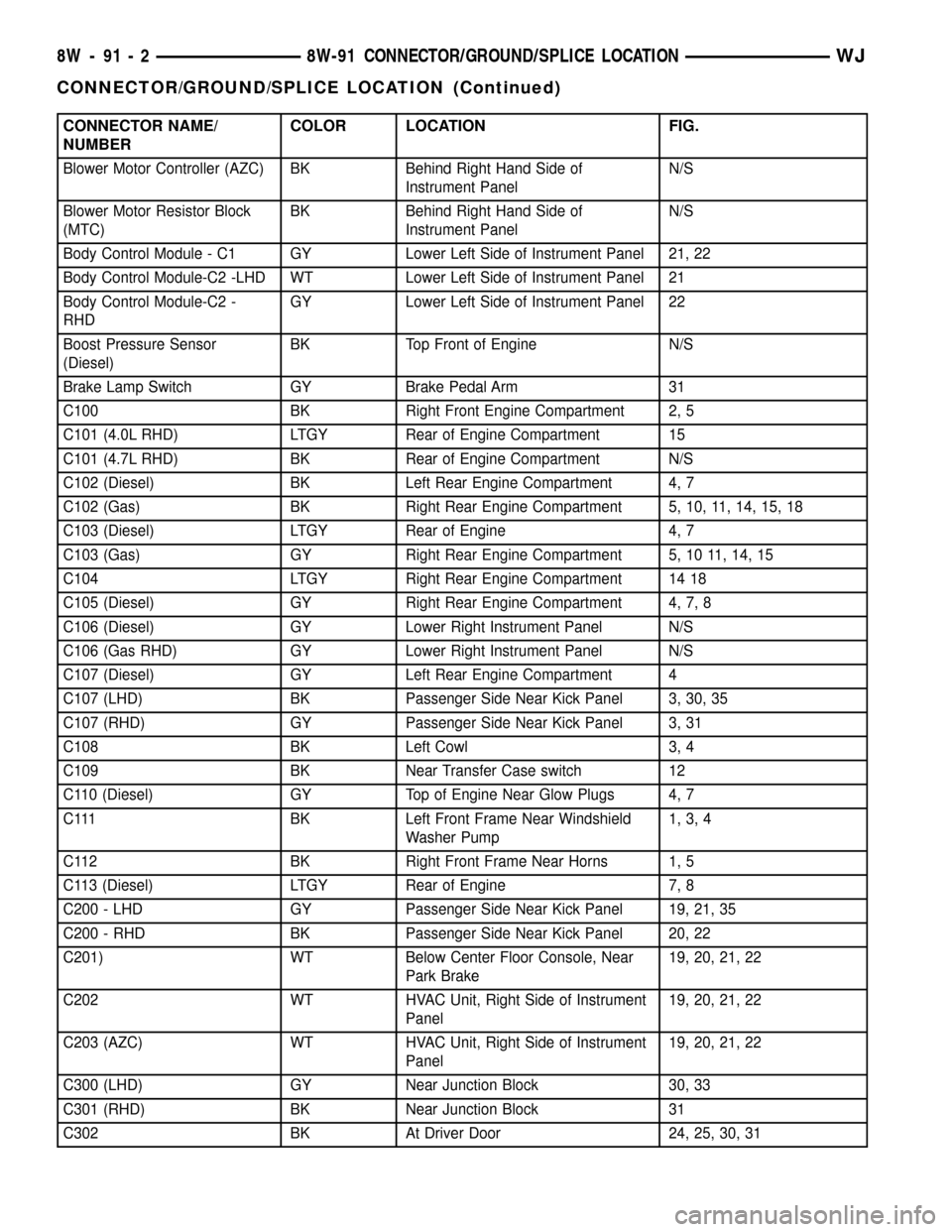
CONNECTOR NAME/
NUMBERCOLOR LOCATION FIG.
Blower Motor Controller (AZC) BK Behind Right Hand Side of
Instrument PanelN/S
Blower Motor Resistor Block
(MTC)BK Behind Right Hand Side of
Instrument PanelN/S
Body Control Module - C1 GY Lower Left Side of Instrument Panel 21, 22
Body Control Module-C2 -LHD WT Lower Left Side of Instrument Panel 21
Body Control Module-C2 -
RHDGY Lower Left Side of Instrument Panel 22
Boost Pressure Sensor
(Diesel)BK Top Front of Engine N/S
Brake Lamp Switch GY Brake Pedal Arm 31
C100 BK Right Front Engine Compartment 2, 5
C101 (4.0L RHD) LTGY Rear of Engine Compartment 15
C101 (4.7L RHD) BK Rear of Engine Compartment N/S
C102 (Diesel) BK Left Rear Engine Compartment 4, 7
C102 (Gas) BK Right Rear Engine Compartment 5, 10, 11, 14, 15, 18
C103 (Diesel) LTGY Rear of Engine 4, 7
C103 (Gas) GY Right Rear Engine Compartment 5, 10 11, 14, 15
C104 LTGY Right Rear Engine Compartment 14 18
C105 (Diesel) GY Right Rear Engine Compartment 4, 7, 8
C106 (Diesel) GY Lower Right Instrument Panel N/S
C106 (Gas RHD) GY Lower Right Instrument Panel N/S
C107 (Diesel) GY Left Rear Engine Compartment 4
C107 (LHD) BK Passenger Side Near Kick Panel 3, 30, 35
C107 (RHD) GY Passenger Side Near Kick Panel 3, 31
C108 BK Left Cowl 3, 4
C109 BK Near Transfer Case switch 12
C110 (Diesel) GY Top of Engine Near Glow Plugs 4, 7
C111 BK Left Front Frame Near Windshield
Washer Pump1, 3, 4
C112 BK Right Front Frame Near Horns 1, 5
C113 (Diesel) LTGY Rear of Engine 7, 8
C200 - LHD GY Passenger Side Near Kick Panel 19, 21, 35
C200 - RHD BK Passenger Side Near Kick Panel 20, 22
C201) WT Below Center Floor Console, Near
Park Brake19, 20, 21, 22
C202 WT HVAC Unit, Right Side of Instrument
Panel19, 20, 21, 22
C203 (AZC) WT HVAC Unit, Right Side of Instrument
Panel19, 20, 21, 22
C300 (LHD) GY Near Junction Block 30, 33
C301 (RHD) BK Near Junction Block 31
C302 BK At Driver Door 24, 25, 30, 31
8W - 91 - 2 8W-91 CONNECTOR/GROUND/SPLICE LOCATIONWJ
CONNECTOR/GROUND/SPLICE LOCATION (Continued)
Page 1244 of 2199
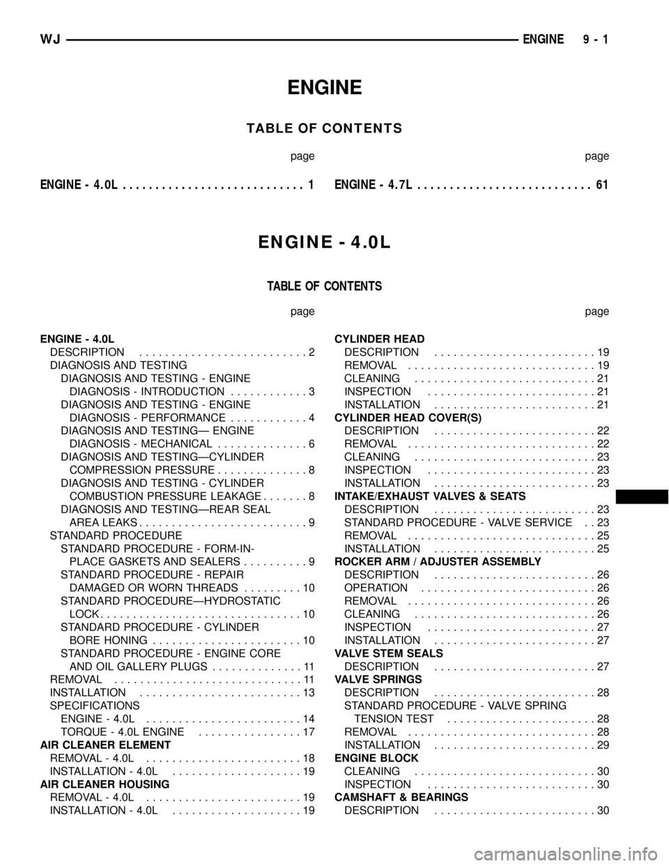
ENGINE
TABLE OF CONTENTS
page page
ENGINE - 4.0L............................ 1ENGINE - 4.7L........................... 61
ENGINE - 4.0L
TABLE OF CONTENTS
page page
ENGINE - 4.0L
DESCRIPTION..........................2
DIAGNOSIS AND TESTING
DIAGNOSIS AND TESTING - ENGINE
DIAGNOSIS - INTRODUCTION............3
DIAGNOSIS AND TESTING - ENGINE
DIAGNOSIS - PERFORMANCE............4
DIAGNOSIS AND TESTINGÐ ENGINE
DIAGNOSIS - MECHANICAL..............6
DIAGNOSIS AND TESTINGÐCYLINDER
COMPRESSION PRESSURE..............8
DIAGNOSIS AND TESTING - CYLINDER
COMBUSTION PRESSURE LEAKAGE.......8
DIAGNOSIS AND TESTINGÐREAR SEAL
AREA LEAKS..........................9
STANDARD PROCEDURE
STANDARD PROCEDURE - FORM-IN-
PLACE GASKETS AND SEALERS..........9
STANDARD PROCEDURE - REPAIR
DAMAGED OR WORN THREADS.........10
STANDARD PROCEDUREÐHYDROSTATIC
LOCK...............................10
STANDARD PROCEDURE - CYLINDER
BORE HONING.......................10
STANDARD PROCEDURE - ENGINE CORE
AND OIL GALLERY PLUGS..............11
REMOVAL.............................11
INSTALLATION.........................13
SPECIFICATIONS
ENGINE - 4.0L........................14
TORQUE - 4.0L ENGINE................17
AIR CLEANER ELEMENT
REMOVAL - 4.0L........................18
INSTALLATION - 4.0L....................19
AIR CLEANER HOUSING
REMOVAL - 4.0L........................19
INSTALLATION - 4.0L....................19CYLINDER HEAD
DESCRIPTION.........................19
REMOVAL.............................19
CLEANING............................21
INSPECTION..........................21
INSTALLATION.........................21
CYLINDER HEAD COVER(S)
DESCRIPTION.........................22
REMOVAL.............................22
CLEANING............................23
INSPECTION..........................23
INSTALLATION.........................23
INTAKE/EXHAUST VALVES & SEATS
DESCRIPTION.........................23
STANDARD PROCEDURE - VALVE SERVICE . . 23
REMOVAL.............................25
INSTALLATION.........................25
ROCKER ARM / ADJUSTER ASSEMBLY
DESCRIPTION.........................26
OPERATION...........................26
REMOVAL.............................26
CLEANING............................26
INSPECTION..........................27
INSTALLATION.........................27
VALVE STEM SEALS
DESCRIPTION.........................27
VALVE SPRINGS
DESCRIPTION.........................28
STANDARD PROCEDURE - VALVE SPRING
TENSION TEST.......................28
REMOVAL.............................28
INSTALLATION.........................29
ENGINE BLOCK
CLEANING............................30
INSPECTION..........................30
CAMSHAFT & BEARINGS
DESCRIPTION.........................30
WJENGINE 9 - 1
Page 1248 of 2199
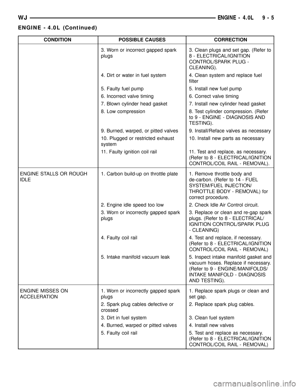
CONDITION POSSIBLE CAUSES CORRECTION
3. Worn or incorrect gapped spark
plugs3. Clean plugs and set gap. (Refer to
8 - ELECTRICAL/IGNITION
CONTROL/SPARK PLUG -
CLEANING).
4. Dirt or water in fuel system 4. Clean system and replace fuel
filter
5. Faulty fuel pump 5. Install new fuel pump
6. Incorrect valve timing 6. Correct valve timing
7. Blown cylinder head gasket 7. Install new cylinder head gasket
8. Low compression 8. Test cylinder compression. (Refer
to 9 - ENGINE - DIAGNOSIS AND
TESTING).
9. Burned, warped, or pitted valves 9. Install/Reface valves as necessary
10. Plugged or restricted exhaust
system10. Install new parts as necessary
11. Faulty ignition coil rail 11. Test and replace, as necessary.
(Refer to 8 - ELECTRICAL/IGNITION
CONTROL/COIL RAIL - REMOVAL).
ENGINE STALLS OR ROUGH
IDLE1. Carbon build-up on throttle plate 1. Remove throttle body and
de-carbon. (Refer to 14 - FUEL
SYSTEM/FUEL INJECTION/
THROTTLE BODY - REMOVAL) for
correct procedure.
2. Engine idle speed too low 2. Check Idle Air Control circuit.
3. Worn or incorrectly gapped spark
plugs3. Replace or clean and re-gap spark
plugs. (Refer to 8 - ELECTRICAL/
IGNITION CONTROL/SPARK PLUG
- CLEANING)
4. Faulty coil rail 4. Test and replace, if necessary.
(Refer to 8 - ELECTRICAL/IGNITION
CONTROL/COIL RAIL - REMOVAL)
5. Intake manifold vacuum leak 5. Inspect intake manifold gasket and
vacuum hoses. Replace if necessary.
(Refer to 9 - ENGINE/MANIFOLDS/
INTAKE MANIFOLD - DIAGNOSIS
AND TESTING).
ENGINE MISSES ON
ACCELERATION1. Worn or incorrectly gapped spark
plugs1. Replace spark plugs or clean and
set gap.
2. Spark plug cables defective or
crossed2. Replace spark plug cables.
3. Dirt in fuel system 3. Clean fuel system
4. Burned, warped or pitted valves 4. Install new valves
5. Faulty coil rail 5. Test and replace as necessary.
(Refer to 8 - ELECTRICAL/IGNITION
CONTROL/COIL RAIL - REMOVAL)
WJENGINE - 4.0L 9 - 5
ENGINE - 4.0L (Continued)
Page 1250 of 2199
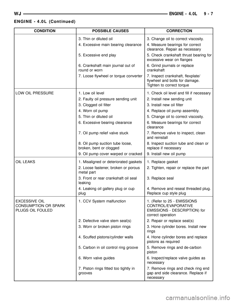
CONDITION POSSIBLE CAUSES CORRECTION
3. Thin or diluted oil 3. Change oil to correct viscosity.
4. Excessive main bearing clearance 4. Measure bearings for correct
clearance. Repair as necessary
5. Excessive end play 5. Check crankshaft thrust bearing for
excessive wear on flanges
6. Crankshaft main journal out of
round or worn6. Grind journals or replace
crankshaft
7. Loose flywheel or torque converter 7. Inspect crankshaft, flexplate/
flywheel and bolts for damage.
Tighten to correct torque
LOW OIL PRESSURE 1. Low oil level 1. Check oil level and fill if necessary
2. Faulty oil pressure sending unit 2. Install new sending unit
3. Clogged oil filter 3. Install new oil filter
4. Worn oil pump 4. Replace oil pump assembly.
5. Thin or diluted oil 5. Change oil to correct viscosity.
6. Excessive bearing clearance 6. Measure bearings for correct
clearance
7. Oil pump relief valve stuck 7. Remove valve to inspect, clean
and reinstall
8. Oil pump suction tube loose,
broken, bent or clogged8. Inspect suction tube and clean or
replace if necessary
9. Oil pump cover warped or cracked 9. Install new oil pump
OIL LEAKS 1. Misaligned or deteriorated gaskets 1. Replace gasket
2. Loose fastener, broken or porous
metal part2. Tighten, repair or replace the part
3. Front or rear crankshaft oil seal
leaking3. Replace seal
4. Leaking oil gallery plug or cup
plug4. Remove and reseal threaded plug.
Replace cup style plug
EXCESSIVE OIL
CONSUMPTION OR SPARK
PLUGS OIL FOULED1. CCV System malfunction 1. (Refer to 25 - EMISSIONS
CONTROL/EVAPORATIVE
EMISSIONS - DESCRIPTION) for
correct operation
2. Defective valve stem seal(s) 2. Repair or replace seal(s)
3. Worn or broken piston rings 3. Hone cylinder bores. Install new
rings
4. Scuffed pistons/cylinder walls 4. Hone cylinder bores and replace
pistons as required
5. Carbon in oil control ring groove 5. Remove rings and de-carbon
piston
6. Worn valve guides 6. Inspect/replace valve guides as
necessary
7. Piston rings fitted too tightly in
grooves7. Remove rings and check ring end
gap and side clearance. Replace if
necessary
WJENGINE - 4.0L 9 - 7
ENGINE - 4.0L (Continued)
Page 1251 of 2199
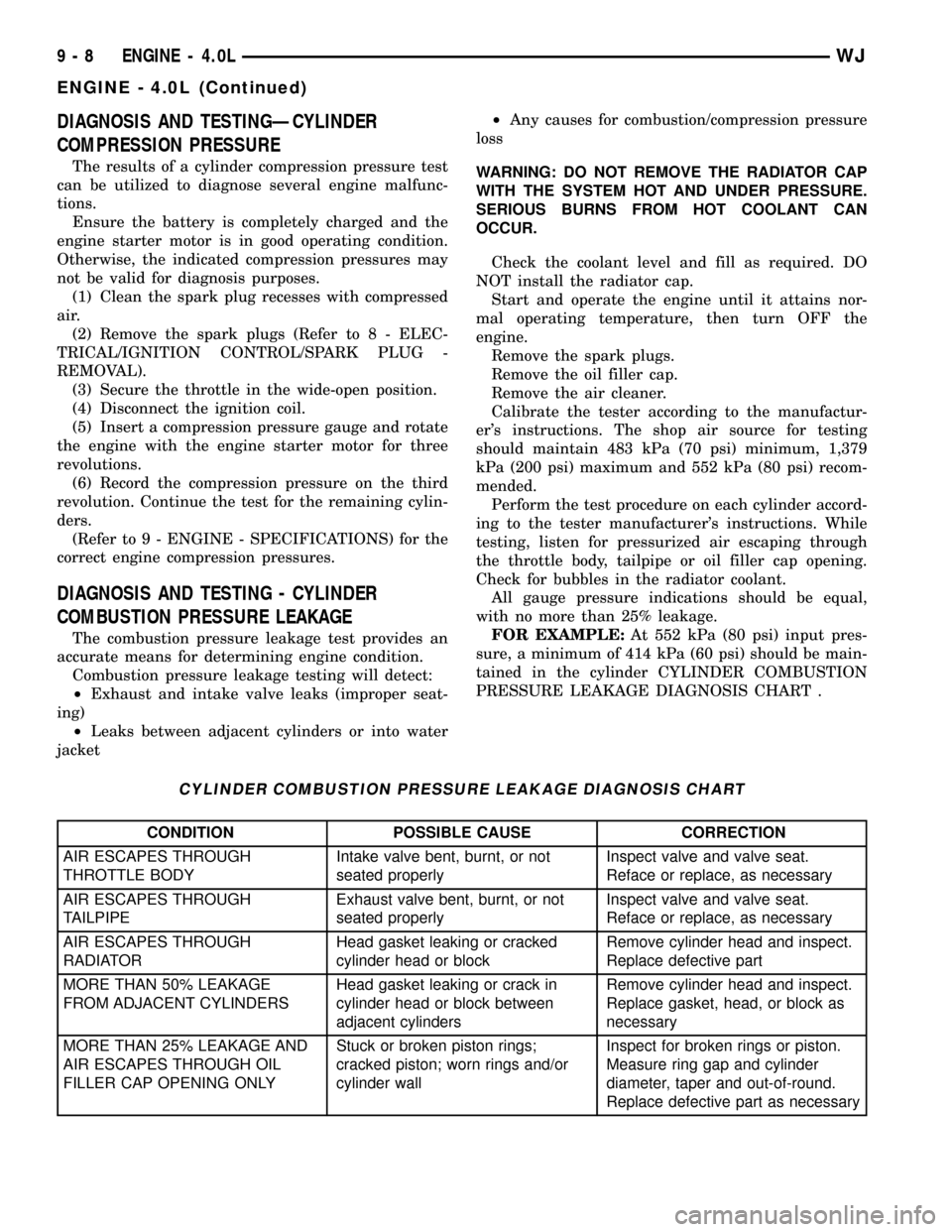
DIAGNOSIS AND TESTINGÐCYLINDER
COMPRESSION PRESSURE
The results of a cylinder compression pressure test
can be utilized to diagnose several engine malfunc-
tions.
Ensure the battery is completely charged and the
engine starter motor is in good operating condition.
Otherwise, the indicated compression pressures may
not be valid for diagnosis purposes.
(1) Clean the spark plug recesses with compressed
air.
(2) Remove the spark plugs (Refer to 8 - ELEC-
TRICAL/IGNITION CONTROL/SPARK PLUG -
REMOVAL).
(3) Secure the throttle in the wide-open position.
(4) Disconnect the ignition coil.
(5) Insert a compression pressure gauge and rotate
the engine with the engine starter motor for three
revolutions.
(6) Record the compression pressure on the third
revolution. Continue the test for the remaining cylin-
ders.
(Refer to 9 - ENGINE - SPECIFICATIONS) for the
correct engine compression pressures.
DIAGNOSIS AND TESTING - CYLINDER
COMBUSTION PRESSURE LEAKAGE
The combustion pressure leakage test provides an
accurate means for determining engine condition.
Combustion pressure leakage testing will detect:
²Exhaust and intake valve leaks (improper seat-
ing)
²Leaks between adjacent cylinders or into water
jacket²Any causes for combustion/compression pressure
loss
WARNING: DO NOT REMOVE THE RADIATOR CAP
WITH THE SYSTEM HOT AND UNDER PRESSURE.
SERIOUS BURNS FROM HOT COOLANT CAN
OCCUR.
Check the coolant level and fill as required. DO
NOT install the radiator cap.
Start and operate the engine until it attains nor-
mal operating temperature, then turn OFF the
engine.
Remove the spark plugs.
Remove the oil filler cap.
Remove the air cleaner.
Calibrate the tester according to the manufactur-
er's instructions. The shop air source for testing
should maintain 483 kPa (70 psi) minimum, 1,379
kPa (200 psi) maximum and 552 kPa (80 psi) recom-
mended.
Perform the test procedure on each cylinder accord-
ing to the tester manufacturer's instructions. While
testing, listen for pressurized air escaping through
the throttle body, tailpipe or oil filler cap opening.
Check for bubbles in the radiator coolant.
All gauge pressure indications should be equal,
with no more than 25% leakage.
FOR EXAMPLE:At 552 kPa (80 psi) input pres-
sure, a minimum of 414 kPa (60 psi) should be main-
tained in the cylinder CYLINDER COMBUSTION
PRESSURE LEAKAGE DIAGNOSIS CHART .
CYLINDER COMBUSTION PRESSURE LEAKAGE DIAGNOSIS CHART
CONDITION POSSIBLE CAUSE CORRECTION
AIR ESCAPES THROUGH
THROTTLE BODYIntake valve bent, burnt, or not
seated properlyInspect valve and valve seat.
Reface or replace, as necessary
AIR ESCAPES THROUGH
TAILPIPEExhaust valve bent, burnt, or not
seated properlyInspect valve and valve seat.
Reface or replace, as necessary
AIR ESCAPES THROUGH
RADIATORHead gasket leaking or cracked
cylinder head or blockRemove cylinder head and inspect.
Replace defective part
MORE THAN 50% LEAKAGE
FROM ADJACENT CYLINDERSHead gasket leaking or crack in
cylinder head or block between
adjacent cylindersRemove cylinder head and inspect.
Replace gasket, head, or block as
necessary
MORE THAN 25% LEAKAGE AND
AIR ESCAPES THROUGH OIL
FILLER CAP OPENING ONLYStuck or broken piston rings;
cracked piston; worn rings and/or
cylinder wallInspect for broken rings or piston.
Measure ring gap and cylinder
diameter, taper and out-of-round.
Replace defective part as necessary
9 - 8 ENGINE - 4.0LWJ
ENGINE - 4.0L (Continued)
Page 1252 of 2199

DIAGNOSIS AND TESTINGÐREAR SEAL AREA
LEAKS
Since it is sometimes difficult to determine the
source of an oil leak in the rear seal area of the
engine, a more involved inspection is necessary. The
following steps should be followed to help pinpoint
the source of the leak.
If the leakage occurs at the crankshaft rear oil seal
area:
(1) Disconnect the battery.
(2) Raise the vehicle.
(3) Remove torque converter or clutch housing
cover and inspect rear of block for evidence of oil.
Use a black light to check for the oil leak:
(a) Circular spray pattern generally indicates
seal leakage or crankshaft damage.
(b) Where leakage tends to run straight down,
possible causes are a porous block, distributor seal,
camshaft bore cup plugs, oil galley pipe plugs, oil
filter runoff, and main bearing cap to cylinder
block mating surfaces.
(4) If no leaks are detected, pressurized the crank-
case as outlined in (Refer to 9 - ENGINE/LUBRICA-
TION - DIAGNOSIS AND TESTING)
CAUTION: Do not exceed 20.6 kPa (3 psi).
(5) If the leak is not detected, very slowly turn the
crankshaft and watch for leakage. If a leak is
detected between the crankshaft and seal while
slowly turning the crankshaft, it is possible the
crankshaft seal surface is damaged. The seal area on
the crankshaft could have minor nicks or scratches
that can be polished out with emery cloth.
CAUTION: Use extreme caution when crankshaft
polishing is necessary to remove minor nicks or
scratches. The crankshaft seal flange is specially
machined to complement the function of the rear oil
seal.
(6) For bubbles that remain steady with shaft
rotation, no further inspection can be done until dis-
assembled. Refer to the service DiagnosisÐMechani-
cal, under the Oil Leak row, for components
inspections on possible causes and corrections.
(7) After the oil leak root cause and appropriate
corrective action have been identified, (Refer to 9 -
ENGINE/ENGINE BLOCK/CRANKSHAFT OIL
SEAL - REAR - REMOVAL), for proper replacement
procedures.
STANDARD PROCEDURE
STANDARD PROCEDURE - FORM-IN-PLACE
GASKETS AND SEALERS
There are numerous places where form-in-place
gaskets are used on the engine. Care must be taken
when applying form-in-place gaskets to assure
obtaining the desired results.Do not use form-in-
place gasket material unless specified.Bead size,
continuity, and location are of great importance. Too
thin a bead can result in leakage while too much can
result in spill-over which can break off and obstruct
fluid feed lines. A continuous bead of the proper
width is essential to obtain a leak-free gasket.
There are numerous types of form-in-place gasket
materials that are used in the engine area. Mopart
Engine RTV GEN II, MopartATF-RTV, and Mopart
Gasket Maker gasket materials, each have different
properties and can not be used in place of the other.
MOPARtENGINE RTV GEN II
MopartEngine RTV GEN II is used to seal com-
ponents exposed to engine oil. This material is a spe-
cially designed black silicone rubber RTV that
retains adhesion and sealing properties when
exposed to engine oil. Moisture in the air causes the
material to cure. This material is available in three
ounce tubes and has a shelf life of one year. After one
year this material will not properly cure. Always
inspect the package for the expiration date before
use.
MOPARtATF RTV
MopartATF RTV is a specifically designed black
silicone rubber RTV that retains adhesion and seal-
ing properties to seal components exposed to auto-
matic transmission fluid, engine coolants, and
moisture. This material is available in three ounce
tubes and has a shelf life of one year. After one year
this material will not properly cure. Always inspect
the package for the expiration date before use.
MOPARtGASKET MAKER
MopartGasket Maker is an anaerobic type gasket
material. The material cures in the absence of air
when squeezed between two metallic surfaces. It will
not cure if left in the uncovered tube. The anaerobic
material is for use between two machined surfaces.
Do not use on flexible metal flanges.
MOPARtGASKET SEALANT
MopartGasket Sealant is a slow drying, perma-
nently soft sealer. This material is recommended for
sealing threaded fittings and gaskets against leakage
of oil and coolant. Can be used on threaded and
machined parts under all temperatures. This mate-
rial is used on engines with multi-layer steel (MLS)
cylinder head gaskets. This material also will pre-
vent corrosion. MopartGasket Sealant is available in
a 13 oz. aerosol can or 4oz./16 oz. can w/applicator.
WJENGINE - 4.0L 9 - 9
ENGINE - 4.0L (Continued)