2002 JEEP GRAND CHEROKEE Knock
[x] Cancel search: KnockPage 1181 of 2199

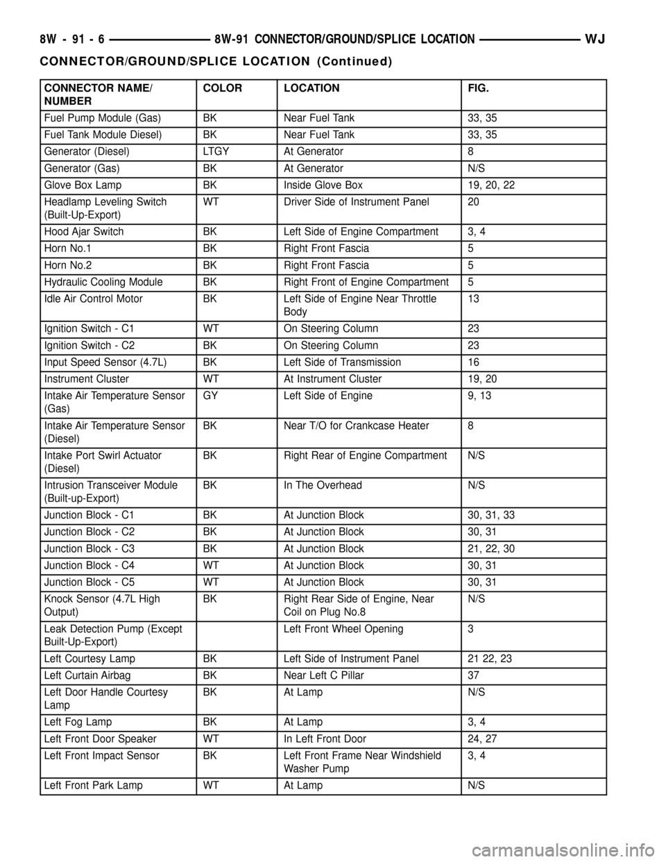
CONNECTOR NAME/
NUMBERCOLOR LOCATION FIG.
Fuel Pump Module (Gas) BK Near Fuel Tank 33, 35
Fuel Tank Module Diesel) BK Near Fuel Tank 33, 35
Generator (Diesel) LTGY At Generator 8
Generator (Gas) BK At Generator N/S
Glove Box Lamp BK Inside Glove Box 19, 20, 22
Headlamp Leveling Switch
(Built-Up-Export)WT Driver Side of Instrument Panel 20
Hood Ajar Switch BK Left Side of Engine Compartment 3, 4
Horn No.1 BK Right Front Fascia 5
Horn No.2 BK Right Front Fascia 5
Hydraulic Cooling Module BK Right Front of Engine Compartment 5
Idle Air Control Motor BK Left Side of Engine Near Throttle
Body13
Ignition Switch - C1 WT On Steering Column 23
Ignition Switch - C2 BK On Steering Column 23
Input Speed Sensor (4.7L) BK Left Side of Transmission 16
Instrument Cluster WT At Instrument Cluster 19, 20
Intake Air Temperature Sensor
(Gas)GY Left Side of Engine 9, 13
Intake Air Temperature Sensor
(Diesel)BK Near T/O for Crankcase Heater 8
Intake Port Swirl Actuator
(Diesel)BK Right Rear of Engine Compartment N/S
Intrusion Transceiver Module
(Built-up-Export)BK In The Overhead N/S
Junction Block - C1 BK At Junction Block 30, 31, 33
Junction Block - C2 BK At Junction Block 30, 31
Junction Block - C3 BK At Junction Block 21, 22, 30
Junction Block - C4 WT At Junction Block 30, 31
Junction Block - C5 WT At Junction Block 30, 31
Knock Sensor (4.7L High
Output)BK Right Rear Side of Engine, Near
Coil on Plug No.8N/S
Leak Detection Pump (Except
Built-Up-Export)Left Front Wheel Opening 3
Left Courtesy Lamp BK Left Side of Instrument Panel 21 22, 23
Left Curtain Airbag BK Near Left C Pillar 37
Left Door Handle Courtesy
LampBK At Lamp N/S
Left Fog Lamp BK At Lamp 3, 4
Left Front Door Speaker WT In Left Front Door 24, 27
Left Front Impact Sensor BK Left Front Frame Near Windshield
Washer Pump3, 4
Left Front Park Lamp WT At Lamp N/S
8W - 91 - 6 8W-91 CONNECTOR/GROUND/SPLICE LOCATIONWJ
CONNECTOR/GROUND/SPLICE LOCATION (Continued)
Page 1465 of 2199

INSTALLATION
INSTALLATION - 4.0L
The IAC motor is located on the throttle body.
(1) Install IAC motor to throttle body.
(2) Install and tighten two mounting bolts (screws)
to 7 N´m (60 in. lbs.) torque.
(3) Install electrical connector.
(4) Install air cleaner duct/air box to throttle body.
INSTALLATION - 4.7L
(1) Install IAC motor to throttle body.
(2) Install and tighten two mounting bolts (screws)
to 7 N´m (60 in. lbs.) torque.
(3) Install electrical connector.
(4) Install air duct/air box to throttle body.
INTAKE AIR TEMPERATURE
SENSOR
DESCRIPTION
The 2±wire Intake Manifold Air Temperature (IAT)
sensor is installed in the intake manifold with the
sensor element extending into the air stream.
The IAT sensor is a two-wire Negative Thermal
Coefficient (NTC) sensor. Meaning, as intake mani-
fold temperature increases, resistance (voltage) in the
sensor decreases. As temperature decreases, resis-
tance (voltage) in the sensor increases.
OPERATION
The IAT sensor provides an input voltage to the
Powertrain Control Module (PCM) indicating the
density of the air entering the intake manifold based
upon intake manifold temperature. At key-on, a
5±volt power circuit is supplied to the sensor from
the PCM. The sensor is grounded at the PCM
through a low-noise, sensor-return circuit.
The PCM uses this input to calculate the following:
²Injector pulse-width
²Adjustment of spark timing (to help prevent
spark knock with high intake manifold air-charge
temperatures)
The resistance values of the IAT sensor is the same
as for the Engine Coolant Temperature (ECT) sensor.
REMOVAL
REMOVAL - 4.0L
The Intake Manifold Air Temperature (IAT) sensor
is installed into the intake manifold plenum near the
front of the throttle body (Fig. 27).
(1) Disconnect electrical connector from sensor.
(2) Remove sensor from intake manifold.
REMOVAL - 4.7L
The Intake Manifold Air Temperature (IAT) sensor
is located on the left side of the intake manifold.
Threaded Type Sensor
(1) Disconnect electrical connector from sensor.
(2) Remove sensor from intake manifold (Fig. 28).
Snap-In Type Sensor
(1) Disconnect electrical connector from IAT sen-
sor.
(2) Clean dirt from intake manifold at sensor base.
(3) Gently lift on small plastic release tab (Fig. 30)
or (Fig. 29) and rotate sensor about 1/4 turn counter-
clockwise for removal.
(4) Check condition of sensor o-ring.
Fig. 27 Intake Manifold Air Sensor LocationÐ4.0L
Engine
1 - MOUNTING BOLTS (4)
2 - THROTTLE BODY
3 - IAC MOTOR
4 - ELEC. CONN.
5 - TPS
6 - MAP SENSOR
7 - ELEC. CONN.
8 - IAT SENSOR
9 - ELEC. CONN.
14 - 46 FUEL INJECTIONWJ
IDLE AIR CONTROL MOTOR (Continued)
Page 1479 of 2199

DIAGNOSIS AND TESTING
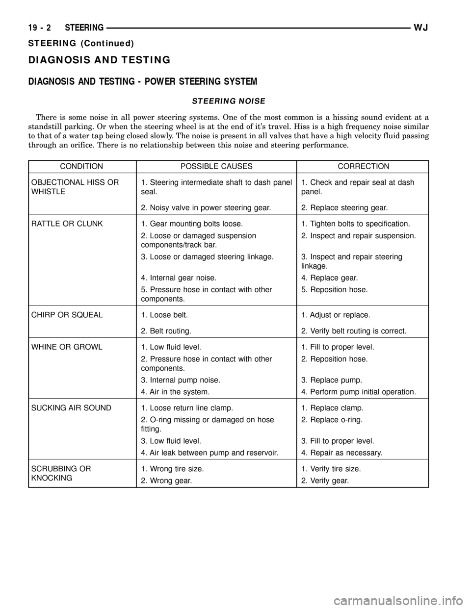
DIAGNOSIS AND TESTING - POWER STEERING SYSTEM
STEERING NOISE
There is some noise in all power steering systems. One of the most common is a hissing sound evident at a
standstill parking. Or when the steering wheel is at the end of it's travel. Hiss is a high frequency noise similar
to that of a water tap being closed slowly. The noise is present in all valves that have a high velocity fluid passing
through an orifice. There is no relationship between this noise and steering performance.
CONDITION POSSIBLE CAUSES CORRECTION
OBJECTIONAL HISS OR
WHISTLE1. Steering intermediate shaft to dash panel
seal.1. Check and repair seal at dash
panel.
2. Noisy valve in power steering gear. 2. Replace steering gear.
RATTLE OR CLUNK 1. Gear mounting bolts loose. 1. Tighten bolts to specification.
2. Loose or damaged suspension
components/track bar.2. Inspect and repair suspension.
3. Loose or damaged steering linkage. 3. Inspect and repair steering
linkage.
4. Internal gear noise. 4. Replace gear.
5. Pressure hose in contact with other
components.5. Reposition hose.
CHIRP OR SQUEAL 1. Loose belt. 1. Adjust or replace.
2. Belt routing. 2. Verify belt routing is correct.
WHINE OR GROWL 1. Low fluid level. 1. Fill to proper level.
2. Pressure hose in contact with other
components.2. Reposition hose.
3. Internal pump noise. 3. Replace pump.
4. Air in the system. 4. Perform pump initial operation.
SUCKING AIR SOUND 1. Loose return line clamp. 1. Replace clamp.
2. O-ring missing or damaged on hose
fitting.2. Replace o-ring.
3. Low fluid level. 3. Fill to proper level.
4. Air leak between pump and reservoir. 4. Repair as necessary.
SCRUBBING OR
KNOCKING1. Wrong tire size. 1. Verify tire size.
2. Wrong gear. 2. Verify gear.
19 - 2 STEERINGWJ
STEERING (Continued)
Page 2161 of 2199

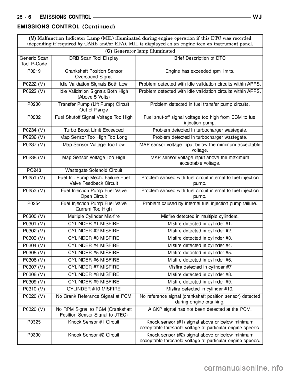
(M)Malfunction Indicator Lamp (MIL) illuminated during engine operation if this DTC was recorded
(depending if required by CARB and/or EPA). MIL is displayed as an engine icon on instrument panel.
(G)Generator lamp illuminated
Generic Scan
Tool P-CodeDRB Scan Tool Display Brief Description of DTC
P0219 Crankshaft Position Sensor
Overspeed SignalEngine has exceeded rpm limits.
P0222 (M) Idle Validation Signals Both Low Problem detected with idle validation circuits within APPS.
P0223 (M) Idle Validation Signals Both High
(Above 5 Volts)Problem detected with idle validation circuits within APPS.
P0230 Transfer Pump (Lift Pump) Circuit
Out of RangeProblem detected in fuel transfer pump circuits.
P0232 Fuel Shutoff Signal Voltage Too High Fuel shut-off signal voltage too high from ECM to fuel
injection pump.
P0234 (M) Turbo Boost Limit Exceeded Problem detected in turbocharger wastegate.
P0236 (M) Map Sensor Too High Too Long Problem detected in turbocharger wastegate.
P0237 (M) Map Sensor Voltage Too Low MAP sensor voltage input below the minimum acceptable
voltage.
P0238 (M) Map Sensor Voltage Too High MAP sensor voltage input above the maximum
acceptable voltage.
PO243 Wastegate Solenoid Circuit
P0251 (M) Fuel Inj. Pump Mech. Failure Fuel
Valve Feedback CircuitProblem sensed with fuel circuit internal to fuel injection
pump.
P0253 (M) Fuel Injection Pump Fuel Valve
Open CircuitProblem sensed with fuel circuit internal to fuel injection
pump.
P0254 Fuel Injection Pump Fuel Valve
Current Too HighProblem caused by internal fuel injection pump failure.
P0300 (M) Multiple Cylinder Mis-fire Misfire detected in multiple cylinders.
P0301 (M) CYLINDER #1 MISFIRE Misfire detected in cylinder #1.
P0302 (M) CYLINDER #2 MISFIRE Misfire detected in cylinder #2.
P0303 (M) CYLINDER #3 MISFIRE Misfire detected in cylinder #3.
P0304 (M) CYLINDER #4 MISFIRE Misfire detected in cylinder #4.
P0305 (M) CYLINDER #5 MISFIRE Misfire detected in cylinder #5.
P0306 (M) CYLINDER #6 MISFIRE Misfire detected in cylinder #6.
P0307 (M) CYLINDER #7 MISFIRE Misfire detected in cylinder #7
P0308 (M) CYLINDER #8 MISFIRE Misfire detected in cylinder #8.
P0309 (M) CYLINDER #9 MISFIRE Misfire detected in cylinder #9.
P0310 (M) CYLINDER #10 MISFIRE Misfire detected in cylinder #10.
P0320 (M) No Crank Referance Signal at PCM No reference signal (crankshaft position sensor) detected
during engine cranking.
P0320 (M) No RPM Signal to PCM (Crankshaft
Position Sensor Signal to JTEC)A CKP signal has not been detected at the PCM.
P0325 Knock Sensor #1 Circuit Knock sensor (#1) signal above or below minimum
acceptable threshold voltage at particular engine speeds.
P0330 Knock Sensor #2 Circuit Knock sensor (#2) signal above or below minimum
acceptable threshold voltage at particular engine speeds.
25 - 6 EMISSIONS CONTROLWJ
EMISSIONS CONTROL (Continued)