Page 1801 of 2199

REMOVAL
(1) Shift transfer case into NEUTRAL.
(2) Raise vehicle.
(3) Remove transfer case drain plug and drain
transfer case lubricant.
(4) Mark front and rear propeller shaft yokes for
alignment reference.
(5) Support transmission with jack stand.
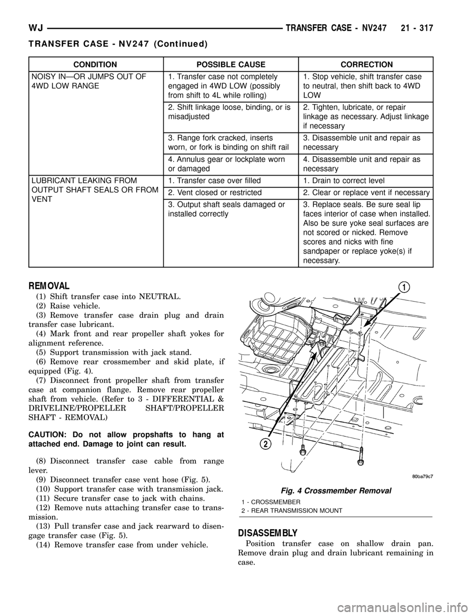
(6) Remove rear crossmember and skid plate, if
equipped (Fig. 3).
(7) Disconnect front/rear propeller shafts at trans-
fer case. (Refer to 3 - DIFFERENTIAL & DRIV-
ELINE/PROPELLER SHAFT/PROPELLER SHAFT -
REMOVAL)
(8) Disconnect transfer case cable from range
lever.
(9) Disconnect transfer case vent hose (Fig. 4) and
transfer case position sensor.
(10) Support transfer case with transmission jack.
(11) Secure transfer case to jack with chains.
(12) Remove nuts attaching transfer case to trans-
mission.(13) Pull transfer case and jack rearward to disen-
gage transfer case.
(14) Remove transfer case from under vehicle.
DISASSEMBLY
REAR RETAINER - NV242LD
(1) Remove output shaft boot. Spread band clamp
that secures boot on slinger with a suitable awl.
Then slide boot off shaft (Fig. 5).
Fig. 3 Crossmember Removal
1 - CROSSMEMBER
2 - REAR TRANSMISSION MOUNT
Fig. 4 Transfer Case Mounting
1 - NV242 TRANSFER CASE
Fig. 5 Output Boot - Typical
1 - SLINGER
2 - BOOT
3-AWL
4 - TRANSFER CASE
21 - 282 TRANSFER CASE - NV242WJ
TRANSFER CASE - NV242 (Continued)
Page 1826 of 2199

NV242HD REAR RETAINER
(1) Apply bead of MopartSealer, or LoctiteŸ
Ultra Gray, to mating surface of rear retainer. Sealer
bead should be a maximum of 3/16 in.
(2) Install rear retainer on rear case. Tighten
retainer bolts to 20-27 N´m (15-20 ft. lbs.) torque.
(3) Install new output shaft bearing snap-ring
(Fig. 91). Lift mainshaft slightly to seat snap-ring in
shaft groove, if necessary.
(4) Apply 3 mm (1/8 in.) wide bead of Mopartgas-
ket maker or silicone adhesive sealer to mounting
surface of extension housing. Allow sealer to set-up
slightly before proceeding.(5) Install extension housing on rear retainer.
(6) Install extension housing bolts and tighten to
35-46 N´m (26-34 ft. lbs.).
COMPANION FLANGE
(1) Lubricate companion flange hub with transmis-
sion fluid and install flange on front shaft.
(2) Install new seal washer on front shaft.
(3) Install flange on front shaft and tighten nut to
122-176 N´m (90-130 ft. lbs.).
INSTALLATION
(1) Mount transfer case on a transmission jack.
(2) Secure transfer case to jack with chains.
(3) Position transfer case under vehicle.
(4) Align transfer case and transmission shafts
and install transfer case on transmission.
(5) Install and tighten transfer case attaching nuts
to 35 N´m (26 ft. lbs.) torque (Fig. 4).
(6) Align and connect propeller shafts. (Refer to 3 -
DIFFERENTIAL & DRIVELINE/PROPELLER
SHAFT/PROPELLER SHAFT - INSTALLATION)
(7) Fill transfer case with correct fluid. Check
transmission fluid level. Correct as necessary.
(8) Install rear crossmember and skid plate, if
equipped. Tighten crossmember bolts to 41 N´m (30
ft. lbs.) torque.
(9) Remove transmission jack and support stand.
(10) Connect shift rod to transfer case range lever.
(11) Connect transfer case vent hose and transfer
case position sensor.
(12) Adjust transfer case shift cable.
(13) Lower vehicle and verify transfer case shift
operation.
Fig. 91 Install Output Bearing Snap-ring
1 - REAR RETAINER
2 - SNAP-RING
3 - REAR BEARING
WJTRANSFER CASE - NV242 21 - 307
TRANSFER CASE - NV242 (Continued)
Page 1836 of 2199

CONDITION POSSIBLE CAUSE CORRECTION
NOISY INÐOR JUMPS OUT OF
4WD LOW RANGE1. Transfer case not completely
engaged in 4WD LOW (possibly
from shift to 4L while rolling)1. Stop vehicle, shift transfer case
to neutral, then shift back to 4WD
LOW
2. Shift linkage loose, binding, or is
misadjusted2. Tighten, lubricate, or repair
linkage as necessary. Adjust linkage
if necessary
3. Range fork cracked, inserts
worn, or fork is binding on shift rail3. Disassemble unit and repair as
necessary
4. Annulus gear or lockplate worn
or damaged4. Disassemble unit and repair as
necessary
LUBRICANT LEAKING FROM
OUTPUT SHAFT SEALS OR FROM
VENT1. Transfer case over filled 1. Drain to correct level
2. Vent closed or restricted 2. Clear or replace vent if necessary
3. Output shaft seals damaged or
installed correctly3. Replace seals. Be sure seal lip
faces interior of case when installed.
Also be sure yoke seal surfaces are
not scored or nicked. Remove
scores and nicks with fine
sandpaper or replace yoke(s) if
necessary.
REMOVAL
(1) Shift transfer case into NEUTRAL.
(2) Raise vehicle.
(3) Remove transfer case drain plug and drain
transfer case lubricant.
(4) Mark front and rear propeller shaft yokes for
alignment reference.
(5) Support transmission with jack stand.
(6) Remove rear crossmember and skid plate, if
equipped (Fig. 4).
(7) Disconnect front propeller shaft from transfer
case at companion flange. Remove rear propeller
shaft from vehicle. (Refer to 3 - DIFFERENTIAL &
DRIVELINE/PROPELLER SHAFT/PROPELLER
SHAFT - REMOVAL)
CAUTION: Do not allow propshafts to hang at
attached end. Damage to joint can result.
(8) Disconnect transfer case cable from range
lever.
(9) Disconnect transfer case vent hose (Fig. 5).
(10) Support transfer case with transmission jack.
(11) Secure transfer case to jack with chains.
(12) Remove nuts attaching transfer case to trans-
mission.
(13) Pull transfer case and jack rearward to disen-
gage transfer case (Fig. 5).
(14) Remove transfer case from under vehicle.
DISASSEMBLY
Position transfer case on shallow drain pan.
Remove drain plug and drain lubricant remaining in
case.
Fig. 4 Crossmember Removal
1 - CROSSMEMBER
2 - REAR TRANSMISSION MOUNT
WJTRANSFER CASE - NV247 21 - 317
TRANSFER CASE - NV247 (Continued)
Page 1855 of 2199

(6) Connect front propeller shaft and install rear
propeller shaft. (Refer to 3 - DIFFERENTIAL &
DRIVELINE/PROPELLER SHAFT/PROPELLER
SHAFT - INSTALLATION)
(7) Fill transfer case with correct fluid. Check
transmission fluid level. Correct as necessary.
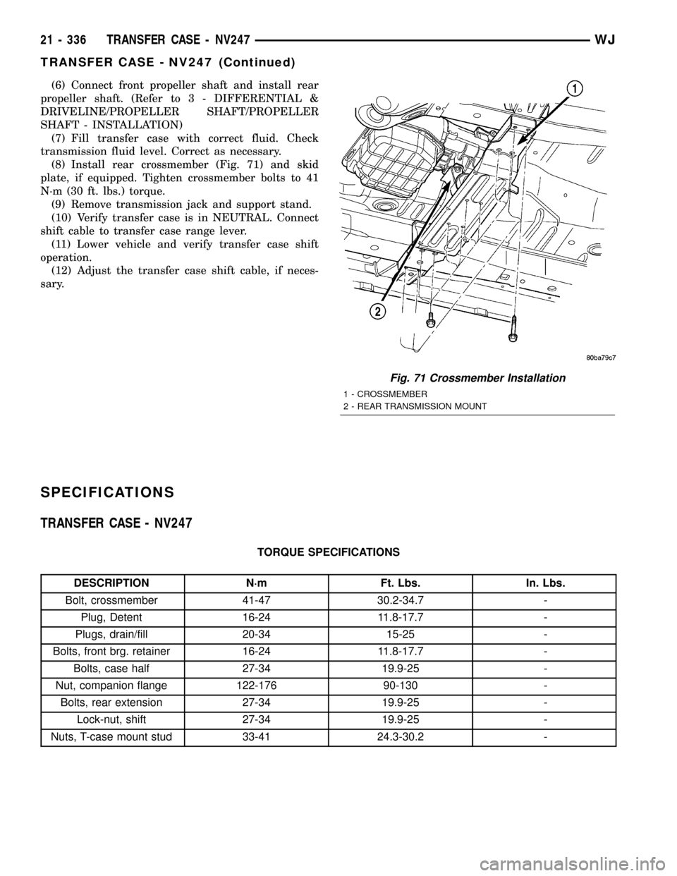
(8) Install rear crossmember (Fig. 71) and skid
plate, if equipped. Tighten crossmember bolts to 41
N´m (30 ft. lbs.) torque.
(9) Remove transmission jack and support stand.
(10) Verify transfer case is in NEUTRAL. Connect
shift cable to transfer case range lever.
(11) Lower vehicle and verify transfer case shift
operation.
(12) Adjust the transfer case shift cable, if neces-
sary.
SPECIFICATIONS
TRANSFER CASE - NV247
TORQUE SPECIFICATIONS
DESCRIPTION N´m Ft. Lbs. In. Lbs.
Bolt, crossmember 41-47 30.2-34.7 -
Plug, Detent 16-24 11.8-17.7 -
Plugs, drain/fill 20-34 15-25 -
Bolts, front brg. retainer 16-24 11.8-17.7 -
Bolts, case half 27-34 19.9-25 -
Nut, companion flange 122-176 90-130 -
Bolts, rear extension 27-34 19.9-25 -
Lock-nut, shift 27-34 19.9-25 -
Nuts, T-case mount stud 33-41 24.3-30.2 -
Fig. 71 Crossmember Installation
1 - CROSSMEMBER
2 - REAR TRANSMISSION MOUNT
21 - 336 TRANSFER CASE - NV247WJ
TRANSFER CASE - NV247 (Continued)
Page:
< prev 1-8 9-16 17-24