2002 JEEP GRAND CHEROKEE tow
[x] Cancel search: towPage 1787 of 2199

OPERATION
The converter impeller (Fig. 115) (driving member),
which is integral to the converter housing and bolted
to the engine drive plate, rotates at engine speed.
The converter turbine (driven member), which reacts
from fluid pressure generated by the impeller, rotates
and turns the transmission input shaft.
TURBINE
As the fluid that was put into motion by the impel-
ler blades strikes the blades of the turbine, some of
the energy and rotational force is transferred into the
turbine and the input shaft. This causes both of them
(turbine and input shaft) to rotate in a clockwise
direction following the impeller. As the fluid is leav-
ing the trailing edges of the turbine's blades it con-
tinues in a ªhinderingº direction back toward the
impeller. If the fluid is not redirected before it strikes
the impeller, it will strike the impeller in such a
direction that it would tend to slow it down.
STATOR
Torque multiplication is achieved by locking the
stator's over-running clutch to its shaft (Fig. 116).
Under stall conditions (the turbine is stationary), the
oil leaving the turbine blades strikes the face of the
stator blades and tries to rotate them in a counter-
clockwise direction. When this happens the over-run-ning clutch of the stator locks and holds the stator
from rotating. With the stator locked, the oil strikes
the stator blades and is redirected into a ªhelpingº
direction before it enters the impeller. This circula-
tion of oil from impeller to turbine, turbine to stator,
and stator to impeller, can produce a maximum
torque multiplication of about 2.4:1. As the turbine
begins to match the speed of the impeller, the fluid
that was hitting the stator in such as way as to
cause it to lock-up is no longer doing so. In this con-
dition of operation, the stator begins to free wheel
and the converter acts as a fluid coupling.
TORQUE CONVERTER CLUTCH (TCC)
In a standard torque converter, the impeller and
turbine are rotating at about the same speed and the
stator is freewheeling, providing no torque multipli-
cation. By applying the turbine's piston and friction
material to the front cover, a total converter engage-
ment can be obtained. The result of this engagement
is a direct 1:1 mechanical link between the engine
and the transmission.
The clutch can be engaged in second, third, fourth,
and fifth gear ranges depending on overdrive control
switch position. If the overdrive control switch is in
the normal ON position, the clutch will engage after
the shift to fourth gear, and above approximately 72
km/h (45 mph). If the control switch is in the OFF
Fig. 115 Torque Converter Fluid Operation - Typical
1 - APPLY PRESSURE 3 - RELEASE PRESSURE
2 - THE PISTON MOVES SLIGHTLY FORWARD 4 - THE PISTON MOVES SLIGHTLY REARWARD
21 - 268 AUTOMATIC TRANSMISSION - 545RFEWJ
TORQUE CONVERTER (Continued)
Page 1796 of 2199

CLEANING
Clean the valve housings, valves, plugs, springs,
and separator plates with a standard parts cleaning
solution only. Do not use gasoline, kerosene, or any
type of caustic solution. (Fig. 131)
Do not immerse any of the electrical components in
cleaning solution. Clean the electrical components by
wiping them off with dry shop towels only.
Dry all except the electrical parts with compressed
air. Make sure all passages are clean and free from
obstructions.Do not use rags or shop towels to
dry or wipe off valve body components. Lint
from these materials can stick to valve body
parts, interfere with valve operation, and clog
filters and fluid passages.
INSPECTION
Inspect all of the valve body mating surfaces for
scratches, nicks, burrs, or distortion. Use a straight-edge to check surface flatness. Minor scratches may
be removed with crocus cloth using only very light
pressure.
Minor distortion of a valve body mating surface
may be corrected by smoothing the surface with a
sheet of crocus cloth. Position the crocus cloth on a
surface plate, sheet of plate glass or equally flat sur-
face. If distortion is severe or any surfaces are
heavily scored, the valve body will have to be
replaced.
Inspect the valves and plugs (Fig. 132) for
scratches, burrs, nicks, or scores. Minor surface
scratches on steel valves and plugs can be removed
with crocus cloth butdo not round off the edges
of the valve or plug lands.Maintaining sharpness
of these edges is vitally important. The edges prevent
foreign matter from lodging between the valves and
plugs and the bore.
Fig. 130 Valve Body Components
1 - SOLENOID SWITCH VALVE
2 - MANUAL VALVE
3 - LOW REVERSE SWITCH VALVE
4 - LOW REVERSE ACCUMULATOR
5 - 2ND CLUTCH ACCUMULATOR
6 - UNDERDRIVE ACCUMULATOR
7 - OVERDRIVE ACCUMULATOR
8 - 4TH CLUTCH ACCUMULATOR
9 - CHECK BALLS (7)
Fig. 131 Valve Body Components
1 - SOLENOID SWITCH VALVE
2 - MANUAL VALVE
3 - LOW REVERSE SWITCH VALVE
4 - LOW REVERSE ACCUMULATOR
5 - 2ND CLUTCH ACCUMULATOR
6 - UNDERDRIVE ACCUMULATOR
7 - OVERDRIVE ACCUMULATOR
8 - 4TH CLUTCH ACCUMULATOR
9 - CHECK BALLS (7)
WJAUTOMATIC TRANSMISSION - 545RFE 21 - 277
VALVE BODY (Continued)
Page 1825 of 2199
REAR RETAINER - NV242LD
(1) Apply bead of MopartSealer, or LoctiteŸ
Ultra Gray, to mating surface of rear retainer. Sealer
bead should be a maximum of 3/16 in.
(2) Install rear retainer on rear case. Tighten
retainer bolts to 20-27 N´m (15-20 ft. lbs.) torque.
(3) Install rear bearing I.D. retaining ring and
spacer on output shaft.
(4) Apply liberal quantity of petroleum jelly to new
rear seal and to output shaft. Petroleum jelly is
needed to protect seal lips during installation.
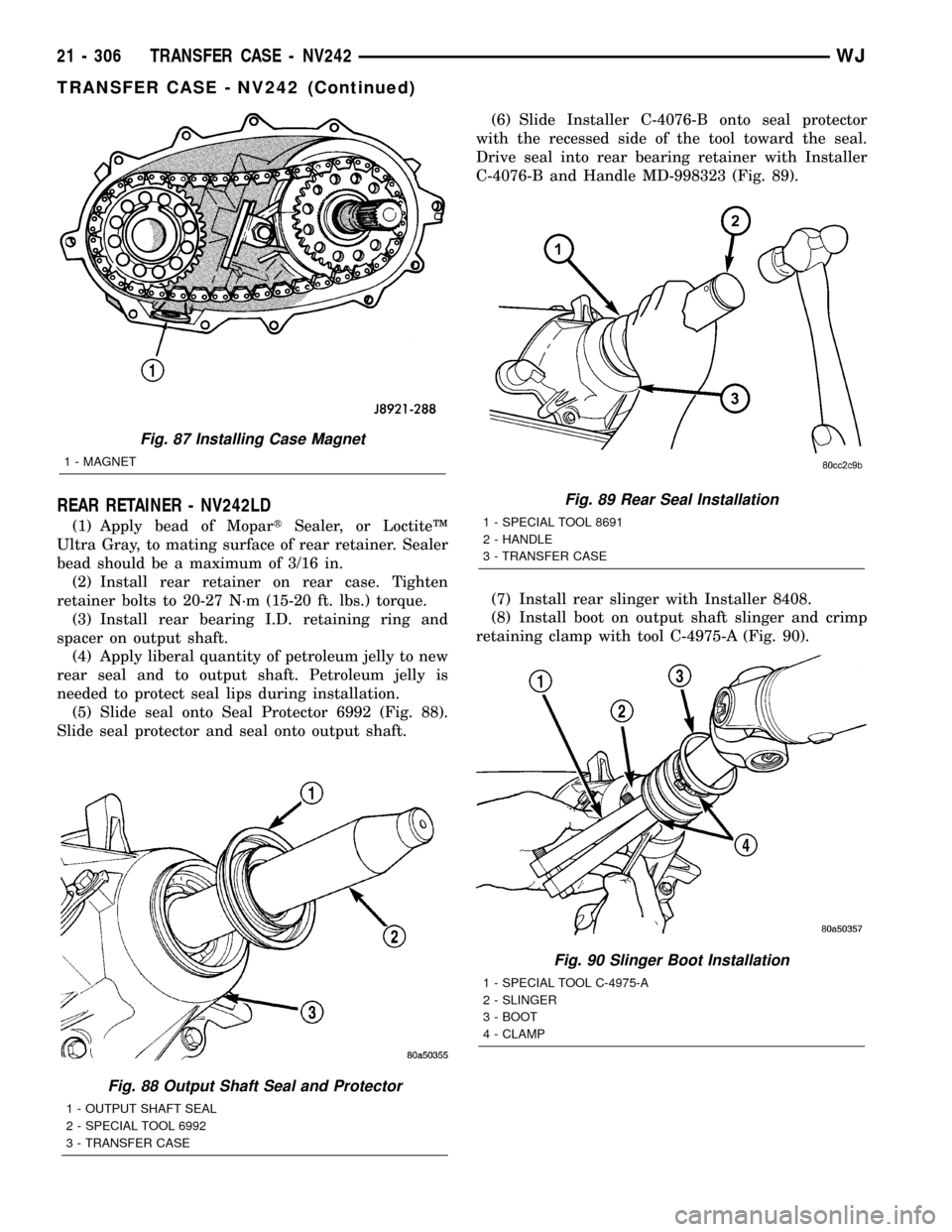
(5) Slide seal onto Seal Protector 6992 (Fig. 88).
Slide seal protector and seal onto output shaft.(6) Slide Installer C-4076-B onto seal protector
with the recessed side of the tool toward the seal.
Drive seal into rear bearing retainer with Installer
C-4076-B and Handle MD-998323 (Fig. 89).
(7) Install rear slinger with Installer 8408.
(8) Install boot on output shaft slinger and crimp
retaining clamp with tool C-4975-A (Fig. 90).
Fig. 88 Output Shaft Seal and Protector
1 - OUTPUT SHAFT SEAL
2 - SPECIAL TOOL 6992
3 - TRANSFER CASE
Fig. 87 Installing Case Magnet
1 - MAGNET
Fig. 89 Rear Seal Installation
1 - SPECIAL TOOL 8691
2 - HANDLE
3 - TRANSFER CASE
Fig. 90 Slinger Boot Installation
1 - SPECIAL TOOL C-4975-A
2 - SLINGER
3 - BOOT
4 - CLAMP
21 - 306 TRANSFER CASE - NV242WJ
TRANSFER CASE - NV242 (Continued)
Page 1829 of 2199
FLUID
STANDARD PROCEDURE - FLUID DRAIN/
REFILL
The fill and drain plugs are both in the rear case
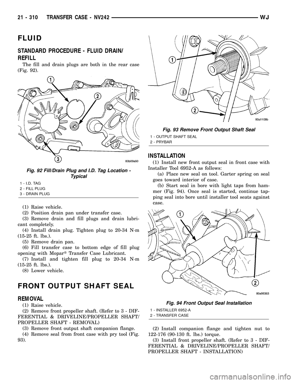
(Fig. 92).
(1) Raise vehicle.
(2) Position drain pan under transfer case.
(3) Remove drain and fill plugs and drain lubri-
cant completely.
(4) Install drain plug. Tighten plug to 20-34 N´m
(15-25 ft. lbs.).
(5) Remove drain pan.
(6) Fill transfer case to bottom edge of fill plug
opening with MopartTransfer Case Lubricant.
(7) Install and tighten fill plug to 20-34 N´m
(15-25 ft. lbs.).
(8) Lower vehicle.
FRONT OUTPUT SHAFT SEAL
REMOVAL
(1) Raise vehicle.
(2) Remove front propeller shaft. (Refer to 3 - DIF-
FERENTIAL & DRIVELINE/PROPELLER SHAFT/
PROPELLER SHAFT - REMOVAL)
(3) Remove front output shaft companion flange.
(4) Remove seal from front case with pry tool (Fig.
93).
INSTALLATION
(1) Install new front output seal in front case with
Installer Tool 6952-A as follows:
(a) Place new seal on tool. Garter spring on seal
goes toward interior of case.
(b) Start seal in bore with light taps from ham-
mer (Fig. 94). Once seal is started, continue tap-
ping seal into bore until installer tool seats against
case.
(2) Install companion flange and tighten nut to
122-176 (90-130 ft. lbs.) torque.
(3) Install front propeller shaft. (Refer to 3 - DIF-
FERENTIAL & DRIVELINE/PROPELLER SHAFT/
PROPELLER SHAFT - INSTALLATION)
Fig. 92 Fill/Drain Plug and I.D. Tag Location -
Typical
1 - I.D. TAG
2 - FILL PLUG
3 - DRAIN PLUG
Fig. 93 Remove Front Output Shaft Seal
1 - OUTPUT SHAFT SEAL
2 - PRYBAR
Fig. 94 Front Output Seal Installation
1 - INSTALLER 6952-A
2 - TRANSFER CASE
21 - 310 TRANSFER CASE - NV242WJ
Page 1843 of 2199
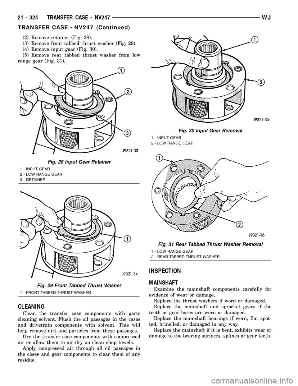
(2) Remove retainer (Fig. 28).
(3) Remove front tabbed thrust washer (Fig. 29).
(4) Remove input gear (Fig. 30).
(5) Remove rear tabbed thrust washer from low
range gear (Fig. 31).
CLEANING
Clean the transfer case components with parts
cleaning solvent. Flush the oil passages in the cases
and drivetrain components with solvent. This will
help remove dirt and particles from these passages.
Dry the transfer case components with compressed
air or allow them to air dry on clean shop towels.
Apply compressed air through all oil passages in
the cases and gear components to clear them of any
residue.
INSPECTION
MAINSHAFT
Examine the mainshaft components carefully for
evidence of wear or damage.
Replace the thrust washers if worn or damaged.
Replace the mainshaft and sprocket gears if the
teeth or gear bores are worn or damaged.
Replace the mainshaft bearings if worn, flat spot-
ted, brinelled, or damaged in any way.
Replace the mainshaft if it is bent, exhibits wear or
damage to the bearing surfaces, splines or gear teeth.
Fig. 28 Input Gear Retainer
1 - INPUT GEAR
2 - LOW RANGE GEAR
3 - RETAINER
Fig. 29 Front Tabbed Thrust Washer
1 - FRONT TABBED THRUST WASHER
Fig. 30 Input Gear Removal
1 - INPUT GEAR
2 - LOW RANGE GEAR
Fig. 31 Rear Tabbed Thrust Washer Removal
1 - LOW RANGE GEAR
2 - REAR TABBED THRUST WASHER
21 - 324 TRANSFER CASE - NV247WJ
TRANSFER CASE - NV247 (Continued)
Page 1846 of 2199
(6) Install new front output seal in front case with
Installer Tool 6952-A as follows:
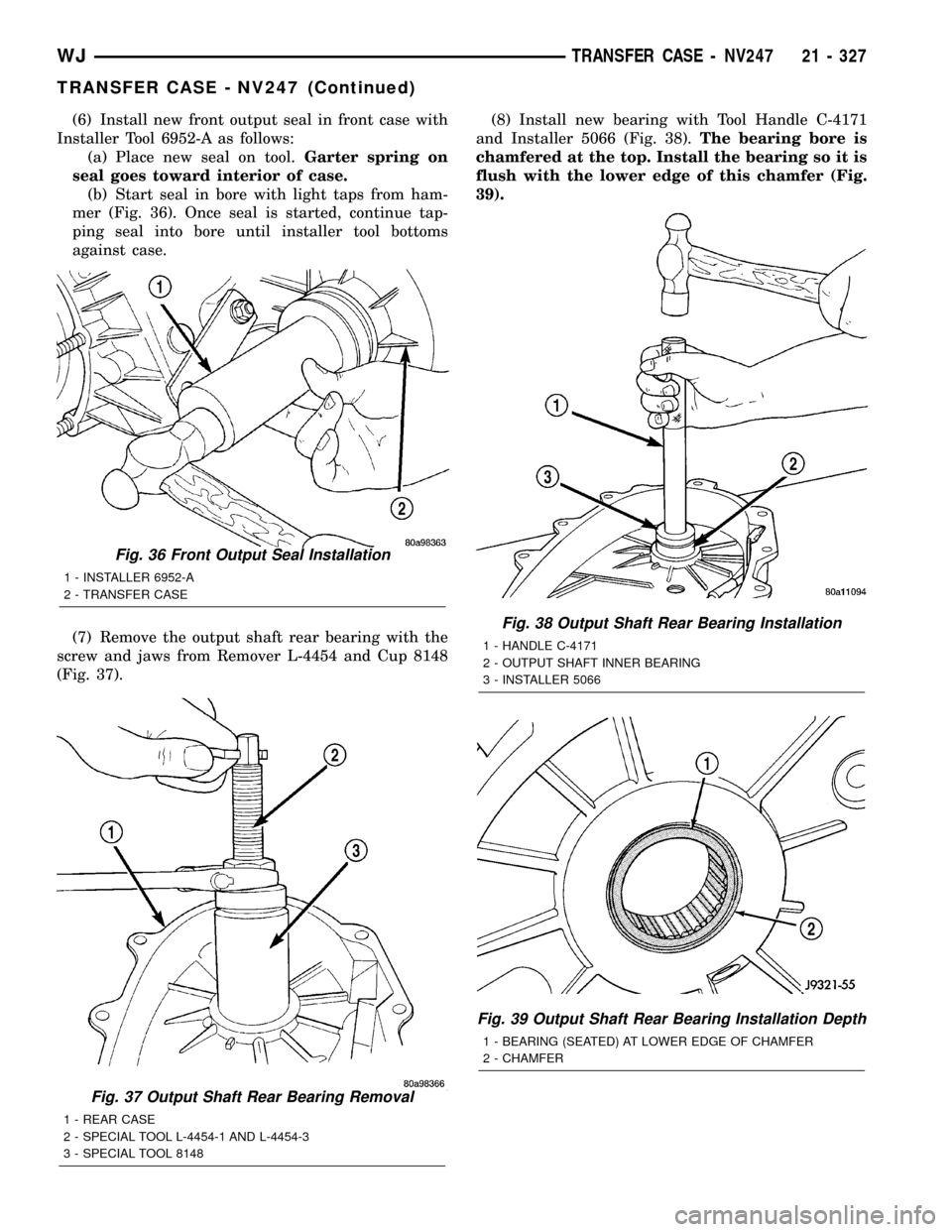
(a) Place new seal on tool.Garter spring on
seal goes toward interior of case.
(b) Start seal in bore with light taps from ham-
mer (Fig. 36). Once seal is started, continue tap-
ping seal into bore until installer tool bottoms
against case.
(7) Remove the output shaft rear bearing with the
screw and jaws from Remover L-4454 and Cup 8148
(Fig. 37).(8) Install new bearing with Tool Handle C-4171
and Installer 5066 (Fig. 38).The bearing bore is
chamfered at the top. Install the bearing so it is
flush with the lower edge of this chamfer (Fig.
39).
Fig. 37 Output Shaft Rear Bearing Removal
1 - REAR CASE
2 - SPECIAL TOOL L-4454-1 AND L-4454-3
3 - SPECIAL TOOL 8148
Fig. 36 Front Output Seal Installation
1 - INSTALLER 6952-A
2 - TRANSFER CASE
Fig. 38 Output Shaft Rear Bearing Installation
1 - HANDLE C-4171
2 - OUTPUT SHAFT INNER BEARING
3 - INSTALLER 5066
Fig. 39 Output Shaft Rear Bearing Installation Depth
1 - BEARING (SEATED) AT LOWER EDGE OF CHAMFER
2 - CHAMFER
WJTRANSFER CASE - NV247 21 - 327
TRANSFER CASE - NV247 (Continued)
Page 1852 of 2199
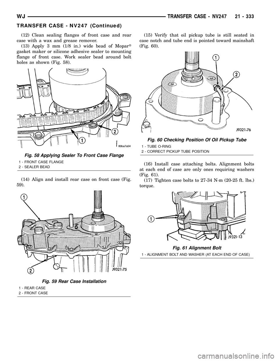
(12) Clean sealing flanges of front case and rear
case with a wax and grease remover.
(13) Apply 3 mm (1/8 in.) wide bead of Mopart
gasket maker or silicone adhesive sealer to mounting
flange of front case. Work sealer bead around bolt
holes as shown (Fig. 58).
(14) Align and install rear case on front case (Fig.
59).(15) Verify that oil pickup tube is still seated in
case notch and tube end is pointed toward mainshaft
(Fig. 60).
(16) Install case attaching bolts. Alignment bolts
at each end of case are only ones requiring washers
(Fig. 61).
(17) Tighten case bolts to 27-34 N´m (20-25 ft. lbs.)
torque.
Fig. 58 Applying Sealer To Front Case Flange
1 - FRONT CASE FLANGE
2 - SEALER BEAD
Fig. 59 Rear Case Installation
1 - REAR CASE
2 - FRONT CASE
Fig. 60 Checking Position Of Oil Pickup Tube
1 - TUBE O-RING
2 - CORRECT PICKUP TUBE POSITION
Fig. 61 Alignment Bolt
1 - ALIGNMENT BOLT AND WASHER (AT EACH END OF CASE)
WJTRANSFER CASE - NV247 21 - 333
TRANSFER CASE - NV247 (Continued)
Page 1853 of 2199
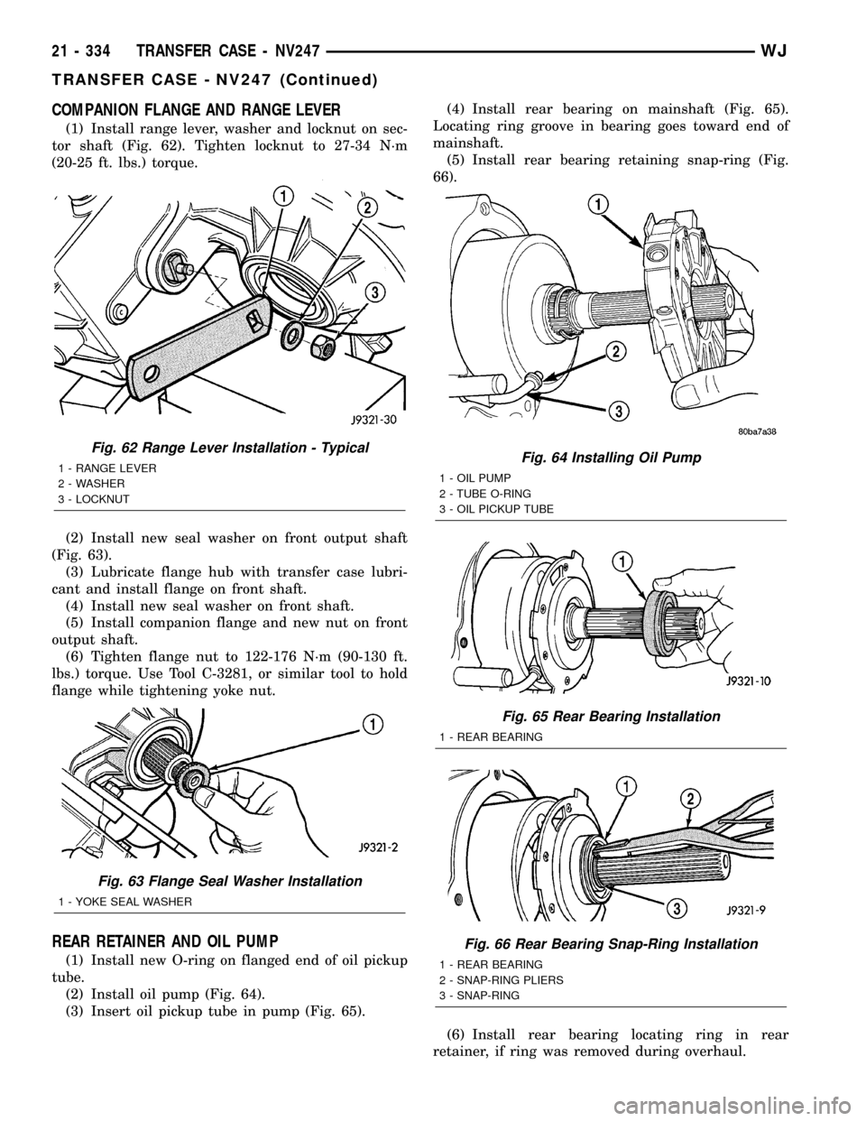
COMPANION FLANGE AND RANGE LEVER
(1) Install range lever, washer and locknut on sec-
tor shaft (Fig. 62). Tighten locknut to 27-34 N´m
(20-25 ft. lbs.) torque.
(2) Install new seal washer on front output shaft
(Fig. 63).
(3) Lubricate flange hub with transfer case lubri-
cant and install flange on front shaft.
(4) Install new seal washer on front shaft.
(5) Install companion flange and new nut on front
output shaft.
(6) Tighten flange nut to 122-176 N´m (90-130 ft.
lbs.) torque. Use Tool C-3281, or similar tool to hold
flange while tightening yoke nut.
REAR RETAINER AND OIL PUMP
(1) Install new O-ring on flanged end of oil pickup
tube.
(2) Install oil pump (Fig. 64).
(3) Insert oil pickup tube in pump (Fig. 65).(4) Install rear bearing on mainshaft (Fig. 65).
Locating ring groove in bearing goes toward end of
mainshaft.
(5) Install rear bearing retaining snap-ring (Fig.
66).
(6) Install rear bearing locating ring in rear
retainer, if ring was removed during overhaul.
Fig. 62 Range Lever Installation - Typical
1 - RANGE LEVER
2 - WASHER
3 - LOCKNUT
Fig. 63 Flange Seal Washer Installation
1 - YOKE SEAL WASHER
Fig. 64 Installing Oil Pump
1 - OIL PUMP
2 - TUBE O-RING
3 - OIL PICKUP TUBE
Fig. 65 Rear Bearing Installation
1 - REAR BEARING
Fig. 66 Rear Bearing Snap-Ring Installation
1 - REAR BEARING
2 - SNAP-RING PLIERS
3 - SNAP-RING
21 - 334 TRANSFER CASE - NV247WJ
TRANSFER CASE - NV247 (Continued)