2002 JEEP GRAND CHEROKEE pin out
[x] Cancel search: pin outPage 649 of 2199
secured loosely to and pivots on the wiper arm hinge
pin to conceal the wiper arm retaining nut. The wide
end of a tapered, stamped steel channel is secured
with a hinge pin to the pivot end of the wiper arm.
One end of a long, rigid, stamped steel strap, with a
small hole near its pivot end, is riveted and crimped
within the narrow end of the stamped steel channel.
The tip of the wiper blade end of this strap is bent
back under itself to form a small hook. Concealed
within the stamped steel channel, one end of a long
spring is engaged with a wire hook on the underside
of the die cast pivot end, while the other end of the
spring is hooked through the small hole in the steel
strap. A molded plastic wiper arm support is snapped
onto the wiper arm strap where it exits the channel.
The entire wiper arm has a satin black finish applied
to all of its visible surfaces.
A wiper arm cannot be adjusted or repaired. If
damaged or faulty, the entire wiper arm unit must be
replaced.
OPERATION
The rear wiper arm is designed to mechanically
transmit the motion from the rear wiper motor out-
put shaft to the rear wiper blade. The wiper arm
must be properly indexed to the motor output shaft
in order to maintain the proper wiper blade travel on
the glass. The wiper arm support is designed to lift
and support the rear wiper arm and blade off of the
glass when the rear wiper blade is parked. This sup-
port and the park ramp on the liftgate outer panel
below the glass also provide an alignment reference
to ensure accurate rear wiper arm and blade instal-
lation. The hole with internal serrations in the wiper
arm pivot end interlocks with the serrations on the
outer circumference of the motor output shaft, allow-
ing positive engagement and finite adjustment of this
connection. A hex nut secures the wiper arm pivot
end to the threads on the motor output shaft and the
pivot cover hinges and snaps over this connection for
a neat appearance. The spring-loaded wiper arm
hinge controls the down-force applied through the tip
of the wiper arm to the wiper blade on the glass. The
hook formation on the tip of the wiper arm provides
a cradle for securing and latching the wiper blade
pivot block to the wiper arm.
REMOVAL
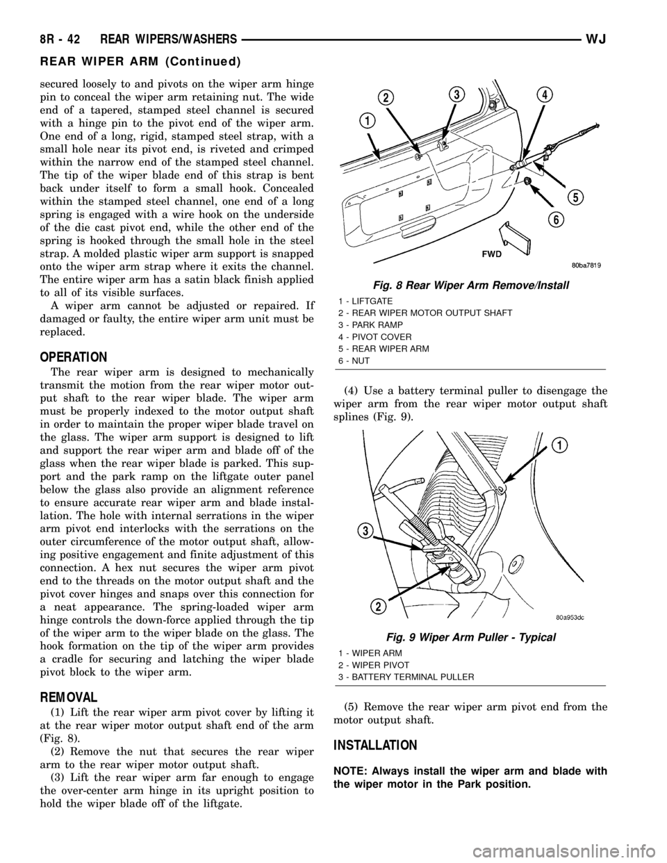
(1) Lift the rear wiper arm pivot cover by lifting it
at the rear wiper motor output shaft end of the arm
(Fig. 8).
(2) Remove the nut that secures the rear wiper
arm to the rear wiper motor output shaft.
(3) Lift the rear wiper arm far enough to engage
the over-center arm hinge in its upright position to
hold the wiper blade off of the liftgate.(4) Use a battery terminal puller to disengage the
wiper arm from the rear wiper motor output shaft
splines (Fig. 9).
(5) Remove the rear wiper arm pivot end from the
motor output shaft.
INSTALLATION
NOTE: Always install the wiper arm and blade with
the wiper motor in the Park position.
Fig. 8 Rear Wiper Arm Remove/Install
1 - LIFTGATE
2 - REAR WIPER MOTOR OUTPUT SHAFT
3 - PARK RAMP
4 - PIVOT COVER
5 - REAR WIPER ARM
6 - NUT
Fig. 9 Wiper Arm Puller - Typical
1 - WIPER ARM
2 - WIPER PIVOT
3 - BATTERY TERMINAL PULLER
8R - 42 REAR WIPERS/WASHERSWJ
REAR WIPER ARM (Continued)
Page 652 of 2199
motor that is secured with screws to the wiper motor
and to the liftgate inner panel.
²Electronic Controls- The rear wiper module
electronic controls include the rear wiper system
electronic logic and rear wiper motor electronic con-
trols. The electronic controls for the motor include an
electronic speed control that speeds the wiper blade
near the center of the glass, but slows the wiper
blade during directional reversals at each end of the
wipe pattern and during wiper blade off-the-glass
parking for quieter operation.
²Motor- The permanent magnet rear wiper
motor is secured with screws to the rear wiper mod-
ule bracket. The wiper motor includes an integral
transmission, and the motor output shaft.
The rear wiper module cannot be adjusted or
repaired. If any component of the module is faulty or
damaged, the entire rear wiper module unit must be
replaced. The motor output shaft gasket, bezel, nut,
and nut cover are available for service replacement.
OPERATION
The rear wiper module receives non-switched bat-
tery current through a fuse in the Junction Block
(JB) and is grounded at all times. The rear wiper
module operation is controlled by the vehicle operator
through battery current signal inputs received by the
rear wiper module electronic controls from the right
multi-function switch on the steering column. The
module also receives an external control input from
the liftgate flip-up glass ajar switch circuit. The rear
wiper module electronic control logic uses these
inputs, its internal inputs, and its programming to
provide continuous wipe, delay wipe, wipe-after-wash
and off-the-glass wiper blade parking. The wiper
blade cycling is controlled by the rear wiper module
electronic controls, which control current flow to the
wiper motor brushes. The wiper motor transmission
converts the rotary output of the wiper motor to the
back and forth wiping motion of the rear wiper arm
and blade on the liftgate glass.
REMOVAL
(1) Disconnect and isolate the battery negative
cable.
(2) Remove the rear wiper arm from the rear
wiper motor output shaft. (Refer to 8 - ELECTRI-
CAL/REAR WIPERS/WASHERS/REAR WIPER ARM
- REMOVAL).
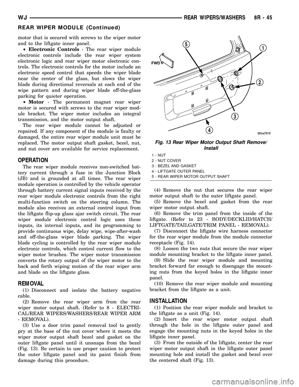
(3) Use a door trim panel removal tool to gently
pry at the base of the nut cover where it meets the
wiper motor output shaft bezel and gasket on the
outer liftgate panel until it unsnaps from the bezel
(Fig. 13). Be certain to use proper caution to protect
the outer liftgate panel and its paint finish from
damage during this procedure.(4) Remove the nut that secures the rear wiper
motor output shaft to the outer liftgate panel.
(5) Remove the bezel and gasket from the rear
wiper motor output shaft.
(6) Remove the trim panel from the inside of the
liftgate. (Refer to 23 - BODY/DECKLID/HATCH/
LIFTGATE/TAILGATE/TRIM PANEL - REMOVAL).
(7) Disconnect the liftgate wire harness connector
for the rear wiper module from the module connector
receptacle (Fig. 14).
(8) Loosen the two nuts that secure the rear wiper
module mounting bracket to the liftgate inner panel.
(9) Slide the rear wiper module and mounting
bracket forward far enough to disengage the mount-
ing nuts from the keyed holes in the liftgate inner
panel.
(10) Remove the rear wiper module and mounting
bracket from the liftgate as a unit.
INSTALLATION
(1) Position the rear wiper module and bracket to
the liftgate as a unit (Fig. 14).
(2) Insert the rear wiper motor output shaft
through the hole in the liftgate outer panel and
engage the mounting nuts in the keyed holes in the
liftgate inner panel.
(3) From the outside of the liftgate, center the rear
wiper motor output shaft in the liftgate outer panel
mounting hole and install the gasket and bezel over
the centered shaft (Fig. 13).
Fig. 13 Rear Wiper Motor Output Shaft Remove/
Install
1 - NUT
2 - NUT COVER
3 - BEZEL AND GASKET
4 - LIFTGATE OUTER PANEL
5 - REAR WIPER MOTOR OUTPUT SHAFT
WJREAR WIPERS/WASHERS 8R - 45
REAR WIPER MODULE (Continued)
Page 654 of 2199

WIRING
TABLE OF CONTENTS
page page
WIRING DIAGRAM INFORMATION....... 8W-01-1
COMPONENT INDEX.................. 8W-02-1
POWER DISTRIBUTION............... 8W-10-1
JUNCTION BLOCK.................... 8W-12-1
GROUND DISTRIBUTION.............. 8W-15-1
BUS COMMUNICATIONS.............. 8W-18-1
CHARGING SYSTEM.................. 8W-20-1
STARTING SYSTEM.................. 8W-21-1
FUEL/IGNITION SYSTEM.............. 8W-30-1
TRANSMISSION CONTROL SYSTEM..... 8W-31-1
VEHICLE SPEED CONTROL............ 8W-33-1
ANTILOCK BRAKES................... 8W-35-1
VEHICLE THEFT SECURITY SYSTEM..... 8W-39-1
INSTRUMENT CLUSTER............... 8W-40-1
HORN/CIGAR LIGHTER/POWER OUTLET . . 8W-41-1
AIR CONDITIONING-HEATER........... 8W-42-1
AIRBAG SYSTEM.................... 8W-43-1
INTERIOR LIGHTING.................. 8W-44-1
BODY CONTROL MODULE............. 8W-45-1AUDIO SYSTEM..................... 8W-47-1
REAR WINDOW DEFOGGER............ 8W-48-1
OVERHEAD CONSOLE................. 8W-49-1
FRONT LIGHTING.................... 8W-50-1
REAR LIGHTING..................... 8W-51-1
TURN SIGNALS...................... 8W-52-1
WIPERS............................ 8W-53-1
TRAILER TOW....................... 8W-54-1
POWER WINDOWS................... 8W-60-1
POWER DOOR LOCKS................ 8W-61-1
POWER MIRRORS................... 8W-62-1
POWER SEATS...................... 8W-63-1
POWER SUNROOF................... 8W-64-1
SPLICE INFORMATION................ 8W-70-1
CONNECTOR PIN-OUT................ 8W-80-1
CONNECTOR/GROUND/SPLICE
LOCATION........................ 8W-91-1
POWER DISTRIBUTION............... 8W-97-1 WJWIRING 8W - 1
Page 661 of 2199

DESCRIPTION - CIRCUIT FUNCTIONS
All circuits in the diagrams use an alpha/numeric
code to identify the wire and it's function. To identify
which circuit code applies to a system, refer to the
Circuit Identification Code Chart. This chart shows
the main circuits only and does not show the second-
ary codes that may apply to some models.
CIRCUIT IDENTIFICATION CODE CHART
CIRCUIT FUNCTION
A BATTERY FEED
B BRAKE CONTROLS
C CLIMATE CONTROLS
D DIAGNOSTIC CIRCUITS
E DIMMING ILLUMINATION
CIRCUITS
F FUSED CIRCUITS
G MONITORING CIRCUITS
(GAUGES)
H OPEN
I NOT USED
J OPEN
K POWERTRAIN CONTROL
MODULE
L EXTERIOR LIGHTING
M INTERIOR LIGHTING
N NOT USED
O NOT USED
P POWER OPTION (BATTERY
FEED)
Q POWER OPTIONS (IGNITION
FEED)
R PASSIVE RESTRAINT
S SUSPENSION/STEERING
T TRANSMISSION/TRANSAXLE/
TRANSFER CASE
U OPEN
V SPEED CONTROL, WIPER/
WASHER
W OPEN
X AUDIO SYSTEMS
Y OPEN
Z GROUNDS
DESCRIPTION - SECTION IDENTIFICATION AND
INFORMATION
The wiring diagrams are grouped into individual
sections. If a component is most likely found in a par-
ticular group, it will be shown complete (all wires,
connectors, and pins) within that group. For exam-
ple, the Auto Shutdown Relay is most likely to be
found in Group 30, so it is shown there complete. It
can, however, be shown partially in another group if
it contains some associated wiring.
Splice diagrams in Section 8W-70 show the entire
splice and provide references to other sections the
splices serves. Section 8W-70 only contains splice dia-
grams that are not shown in their entirety some-
where else in the wiring diagrams.
Section 8W-80 shows each connector and the cir-
cuits involved with that connector. The connectors
are identified using the name/number on the dia-
gram pages.
WIRING SECTION CHART
GROUP TOPIC
8W-01 thru
8W-09General information and Diagram
Overview
8W-10 thru
8W-19Main Sources of Power and
Vehicle Grounding
8W-20 thru
8W-29Starting and Charging
8W-30 thru
8W-39Powertrain/Drivetrain Systems
8W-40 thru
8W-49Body Electrical items and A/C
8W-50 thru
8W-59Exterior Lighting, Wipers and
Trailer Tow
8W-60 thru
8W-69Power Accessories
8W-70 Splice Information
8W-80 Connector Pin Outs
8W-91 Connector, Ground and Splice
Locations
8W - 01 - 6 8W-01 WIRING DIAGRAM INFORMATIONWJ
WIRING DIAGRAM INFORMATION (Continued)
Page 666 of 2199

CONNECTOR
REMOVAL
(1) Disconnect battery.
(2) Release Connector Lock (Fig. 10).
(3) Disconnect the connector being repaired from
its mating half/component.
(4) Remove the dress cover (if applicable) (Fig. 10).
(5) Release the Secondary Terminal Lock, if
required (Fig. 11).
(6) Position the connector locking finger away from
the terminal using the proper special tool. Pull on
the wire to remove the terminal from the connector
(Fig. 12).
INSTALLATION
(1) Insert the removed terminal in the same cavity
on the repair connector.
(2) Repeat steps for each terminal in the connec-
tor, being sure that all wires are inserted into the
proper cavities. For additional connector pin-out
identification, refer to the wiring diagrams.
(3) When the connector is re-assembled, the sec-
ondary terminal lock must be placed in the locked
position to prevent terminal push out.
(4) Replace dress cover (if applicable).
(5) Connect connector to its mating half/compo-
nent.
(6) Connect battery and test all affected systems.
Fig. 10 REMOVAL OF DRESS COVER
1 - DRESS COVER
2 - CONNECTOR LOCK
3 - CONNECTOR
WJ8W-01 WIRING DIAGRAM INFORMATION 8W - 01 - 11
Page 670 of 2199
WIRE
STANDARD PROCEDURE - WIRE SPLICING
When splicing a wire, it is important that the cor-
rect gage be used as shown in the wiring diagrams.
(1) Remove one-half (1/2) inch of insulation from
each wire that needs to be spliced.
(2) Place a piece of adhesive lined heat shrink tub-
ing on one side of the wire. Make sure the tubing will
be long enough to cover and seal the entire repair
area.
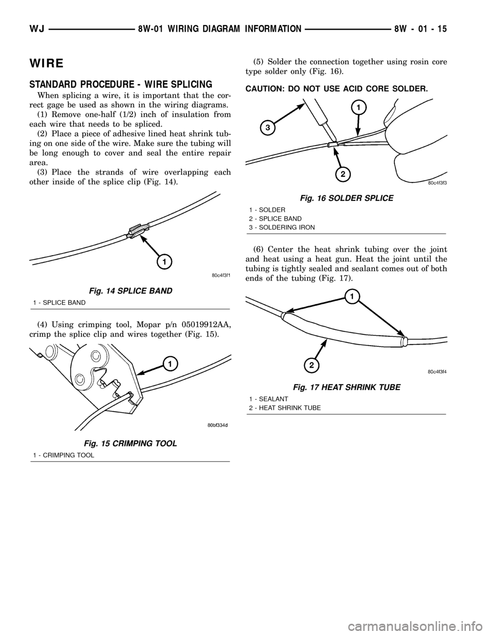
(3) Place the strands of wire overlapping each
other inside of the splice clip (Fig. 14).
(4) Using crimping tool, Mopar p/n 05019912AA,
crimp the splice clip and wires together (Fig. 15).(5) Solder the connection together using rosin core
type solder only (Fig. 16).
CAUTION: DO NOT USE ACID CORE SOLDER.
(6) Center the heat shrink tubing over the joint
and heat using a heat gun. Heat the joint until the
tubing is tightly sealed and sealant comes out of both
ends of the tubing (Fig. 17).
Fig. 14 SPLICE BAND
1 - SPLICE BAND
Fig. 15 CRIMPING TOOL
1 - CRIMPING TOOL
Fig. 16 SOLDER SPLICE
1 - SOLDER
2 - SPLICE BAND
3 - SOLDERING IRON
Fig. 17 HEAT SHRINK TUBE
1 - SEALANT
2 - HEAT SHRINK TUBE
WJ8W-01 WIRING DIAGRAM INFORMATION 8W - 01 - 15
Page 1048 of 2199
8W-80 CONNECTOR PIN-OUT
Component Page
A/C COMPRESSOR CLUTCH.......... 8W-80-6
A/C PRESSURE TRANSDUCER........ 8W-80-6
ACCELERATOR PEDAL POSITION
SENSOR (DIESEL)................. 8W-80-6
ADJUSTABLE PEDALS MODULE
(EXCEPT BUILT-UP-EXPORT)....... 8W-80-6
ADJUSTABLE PEDALS MOTOR/SENSOR
ASSEMBLY (EXCEPT
BUILT-UP-EXPORT)............... 8W-80-7
ADJUSTABLE PEDALS SWITCH (EXCEPT
BUILT-UP-EXPORT)............... 8W-80-7
AIRBAG CONTROL MODULE C1
(ORC C1)........................ 8W-80-7
AIRBAG CONTROL MODULE C2
(ORC C2)........................ 8W-80-8
AMBIENT TEMPERATURE SENSOR.... 8W-80-8
ANTENNA MODULE
(BUILT-UP-EXPORT)............... 8W-80-8
ASH RECEIVER LAMP............... 8W-80-9
AUTOMATIC DAY/NIGHT MIRROR..... 8W-80-9
AUTOMATIC HEADLAMP LIGHT
SENSOR/VTSS LED................ 8W-80-9
AUTOMATIC ZONE CONTROL
MODULE C1 (AZC)................ 8W-80-9
AUTOMATIC ZONE CONTROL
MODULE C2 (AZC)............... 8W-80-10
BATTERY TEMPERATURE SENSOR . . . 8W-80-10
BLOWER MOTOR.................. 8W-80-10
BLOWER MOTOR CONTROLLER
(AZC).......................... 8W-80-10
BLOWER MOTOR RESISTOR
BLOCK (MTC)................... 8W-80-10
BODY CONTROL MODULE C1........ 8W-80-11
BODY CONTROL MODULE C2........ 8W-80-11
BOOST PRESSURE SENSOR
(DIESEL)....................... 8W-80-12
BRAKE LAMP SWITCH.............. 8W-80-12
C100............................. 8W-80-12
C100............................. 8W-80-12
C101 (4.0L RHD)................... 8W-80-12
C101 (4.0L RHD)................... 8W-80-13
C101 (4.7L RHD)................... 8W-80-13
C101 (4.7L RHD)................... 8W-80-13
C102 (DIESEL)..................... 8W-80-14
C102 (DIESEL)..................... 8W-80-14
C102 (GAS RHD)................... 8W-80-14
C102 (GAS RHD)................... 8W-80-15
C103 (DIESEL)..................... 8W-80-15
C103 (DIESEL)..................... 8W-80-15
C103 (GAS)........................ 8W-80-16
C103 (GAS)........................ 8W-80-16
C104............................. 8W-80-17
C104............................. 8W-80-17Component Page
C105 (DIESEL)..................... 8W-80-17
C105 (DIESEL)..................... 8W-80-18
C106 (DIESEL)..................... 8W-80-18
C106 (DIESEL)..................... 8W-80-20
C106 (GAS)........................ 8W-80-22
C106 (GAS)........................ 8W-80-24
C107 (DIESEL)..................... 8W-80-26
C107 (DIESEL)..................... 8W-80-28
C107 (GAS)........................ 8W-80-30
C107 (GAS)........................ 8W-80-32
C108............................. 8W-80-33
C108............................. 8W-80-33
C109............................. 8W-80-33
C109............................. 8W-80-34
C110 (DIESEL)..................... 8W-80-34
C110 (DIESEL)..................... 8W-80-34
C111 ............................. 8W-80-34
C111 ............................. 8W-80-34
C112 ............................. 8W-80-35
C112 ............................. 8W-80-35
C113 (DIESEL)..................... 8W-80-35
C113 (DIESEL)..................... 8W-80-35
C200............................. 8W-80-36
C200............................. 8W-80-38
C201 (DIESEL)..................... 8W-80-39
C201 (DIESEL)..................... 8W-80-39
C202 (AZC)........................ 8W-80-40
C202 (AZC)........................ 8W-80-40
C202 (MTC)....................... 8W-80-41
C202 (MTC)....................... 8W-80-41
C203 (AZC)........................ 8W-80-41
C203 (AZC)........................ 8W-80-41
C300 (LHD)........................ 8W-80-42
C300 (LHD)........................ 8W-80-44
C301 (RHD)....................... 8W-80-46
C301 (RHD)....................... 8W-80-48
C302............................. 8W-80-49
C302............................. 8W-80-50
C303............................. 8W-80-50
C303............................. 8W-80-51
C304............................. 8W-80-51
C304............................. 8W-80-51
C306............................. 8W-80-52
C306............................. 8W-80-52
C307............................. 8W-80-52
C307............................. 8W-80-52
C308............................. 8W-80-53
C308............................. 8W-80-53
C309............................. 8W-80-53
C309............................. 8W-80-54
C310 (BUILT-UP-EXPORT)........... 8W-80-54
C310 (BUILT-UP-EXPORT)........... 8W-80-54
WJ8W-80 CONNECTOR PIN-OUT 8W - 80 - 1
Page 1049 of 2199
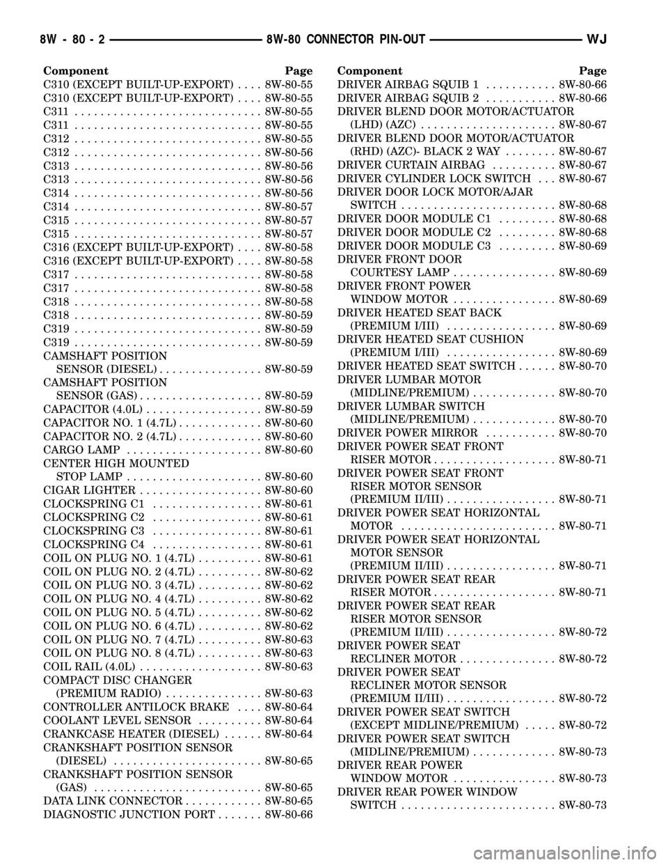
Component Page
C310 (EXCEPT BUILT-UP-EXPORT).... 8W-80-55
C310 (EXCEPT BUILT-UP-EXPORT).... 8W-80-55
C311 ............................. 8W-80-55
C311 ............................. 8W-80-55
C312............................. 8W-80-55
C312............................. 8W-80-56
C313............................. 8W-80-56
C313............................. 8W-80-56
C314............................. 8W-80-56
C314............................. 8W-80-57
C315............................. 8W-80-57
C315............................. 8W-80-57
C316 (EXCEPT BUILT-UP-EXPORT).... 8W-80-58
C316 (EXCEPT BUILT-UP-EXPORT).... 8W-80-58
C317............................. 8W-80-58
C317............................. 8W-80-58
C318............................. 8W-80-58
C318............................. 8W-80-59
C319............................. 8W-80-59
C319............................. 8W-80-59
CAMSHAFT POSITION
SENSOR (DIESEL)................ 8W-80-59
CAMSHAFT POSITION
SENSOR (GAS)................... 8W-80-59
CAPACITOR (4.0L).................. 8W-80-59
CAPACITOR NO. 1 (4.7L)............. 8W-80-60
CAPACITOR NO. 2 (4.7L)............. 8W-80-60
CARGO LAMP..................... 8W-80-60
CENTER HIGH MOUNTED
STOP LAMP..................... 8W-80-60
CIGAR LIGHTER................... 8W-80-60
CLOCKSPRING C1................. 8W-80-61
CLOCKSPRING C2................. 8W-80-61
CLOCKSPRING C3................. 8W-80-61
CLOCKSPRING C4................. 8W-80-61
COIL ON PLUG NO. 1 (4.7L).......... 8W-80-61
COIL ON PLUG NO. 2 (4.7L).......... 8W-80-62
COIL ON PLUG NO. 3 (4.7L).......... 8W-80-62
COIL ON PLUG NO. 4 (4.7L).......... 8W-80-62
COIL ON PLUG NO. 5 (4.7L).......... 8W-80-62
COIL ON PLUG NO. 6 (4.7L).......... 8W-80-62
COIL ON PLUG NO. 7 (4.7L).......... 8W-80-63
COIL ON PLUG NO. 8 (4.7L).......... 8W-80-63
COIL RAIL (4.0L)................... 8W-80-63
COMPACT DISC CHANGER
(PREMIUM RADIO)............... 8W-80-63
CONTROLLER ANTILOCK BRAKE.... 8W-80-64
COOLANT LEVEL SENSOR.......... 8W-80-64
CRANKCASE HEATER (DIESEL)...... 8W-80-64
CRANKSHAFT POSITION SENSOR
(DIESEL)....................... 8W-80-65
CRANKSHAFT POSITION SENSOR
(GAS).......................... 8W-80-65
DATA LINK CONNECTOR............ 8W-80-65
DIAGNOSTIC JUNCTION PORT....... 8W-80-66Component Page
DRIVER AIRBAG SQUIB 1........... 8W-80-66
DRIVER AIRBAG SQUIB 2........... 8W-80-66
DRIVER BLEND DOOR MOTOR/ACTUATOR
(LHD) (AZC)..................... 8W-80-67
DRIVER BLEND DOOR MOTOR/ACTUATOR
(RHD) (AZC)- BLACK 2 WAY........ 8W-80-67
DRIVER CURTAIN AIRBAG.......... 8W-80-67
DRIVER CYLINDER LOCK SWITCH . . . 8W-80-67
DRIVER DOOR LOCK MOTOR/AJAR
SWITCH........................ 8W-80-68
DRIVER DOOR MODULE C1......... 8W-80-68
DRIVER DOOR MODULE C2......... 8W-80-68
DRIVER DOOR MODULE C3......... 8W-80-69
DRIVER FRONT DOOR
COURTESY LAMP................ 8W-80-69
DRIVER FRONT POWER
WINDOW MOTOR................ 8W-80-69
DRIVER HEATED SEAT BACK
(PREMIUM I/III)................. 8W-80-69
DRIVER HEATED SEAT CUSHION
(PREMIUM I/III)................. 8W-80-69
DRIVER HEATED SEAT SWITCH...... 8W-80-70
DRIVER LUMBAR MOTOR
(MIDLINE/PREMIUM)............. 8W-80-70
DRIVER LUMBAR SWITCH
(MIDLINE/PREMIUM)............. 8W-80-70
DRIVER POWER MIRROR........... 8W-80-70
DRIVER POWER SEAT FRONT
RISER MOTOR................... 8W-80-71
DRIVER POWER SEAT FRONT
RISER MOTOR SENSOR
(PREMIUM II/III)................. 8W-80-71
DRIVER POWER SEAT HORIZONTAL
MOTOR........................ 8W-80-71
DRIVER POWER SEAT HORIZONTAL
MOTOR SENSOR
(PREMIUM II/III)................. 8W-80-71
DRIVER POWER SEAT REAR
RISER MOTOR................... 8W-80-71
DRIVER POWER SEAT REAR
RISER MOTOR SENSOR
(PREMIUM II/III)................. 8W-80-72
DRIVER POWER SEAT
RECLINER MOTOR............... 8W-80-72
DRIVER POWER SEAT
RECLINER MOTOR SENSOR
(PREMIUM II/III)................. 8W-80-72
DRIVER POWER SEAT SWITCH
(EXCEPT MIDLINE/PREMIUM)..... 8W-80-72
DRIVER POWER SEAT SWITCH
(MIDLINE/PREMIUM)............. 8W-80-73
DRIVER REAR POWER
WINDOW MOTOR................ 8W-80-73
DRIVER REAR POWER WINDOW
SWITCH........................ 8W-80-73
8W - 80 - 2 8W-80 CONNECTOR PIN-OUTWJ