2002 JEEP GRAND CHEROKEE torque specifications
[x] Cancel search: torque specificationsPage 60 of 2199
FRONT AXLE - 186FBI
TABLE OF CONTENTS
page page
FRONT AXLE - 186FBI
DESCRIPTION.........................15
OPERATION...........................15
DIAGNOSIS AND TESTING................16
REMOVAL.............................20
INSTALLATION.........................21
ADJUSTMENTS........................21
SPECIFICATIONS.......................30
SPECIAL TOOLS.......................31
AXLE SHAFTS
REMOVAL.............................34
INSTALLATION.........................34
AXLE SHAFT SEALS
REMOVAL.............................35
INSTALLATION.........................35
AXLE - C/V JOINT
REMOVAL.............................35
INSTALLATION.........................35
AXLE - U-JOINT
REMOVAL.............................36INSTALLATION.........................37
PINION SEAL
REMOVAL.............................37
INSTALLATION.........................37
COLLAPSIBLE SPACER
REMOVAL.............................39
INSTALLATION.........................39
DIFFERENTIAL
REMOVAL.............................40
DISASSEMBLY.........................42
ASSEMBLY............................42
INSTALLATION.........................43
DIFFERENTIAL CASE BEARINGS
REMOVAL.............................44
INSTALLATION.........................44
PINION GEAR/RING GEAR
REMOVAL.............................45
INSTALLATION.........................46
FRONT AXLE - 186FBI
DESCRIPTION
The Front Beam-design Iron (FBI) axle consists of
a cast iron differential housing with axle shaft tubes
extending from either side. The tubes are pressed
into the differential housing and welded. The axles
are semi-floating axle shafts, meaning the loads are
supported by the hub bearings. The axle shafts are
retained by nuts at the hub bearings.
The differential case is a one-piece design. Differ-
ential bearing preload and ring gear backlash is
adjusted by the use of shims located between the dif-
ferential bearing cups and housing. Pinion bearing
preload is set and maintained by the use of a collaps-
ible spacer. A differential cover provides a means for
inspection and servicing.
An optional Vari-Loktdifferential has a one-piece
differential case which contains the gerotor pump
assembly and the clutch mechinism. This unit is ser-
viced as an assembly.
OPERATION
The axle receives power from the transfer case
through the front propeller shaft. The front propeller
shaft is connected to the pinion gear which rotatesthe differential through the gear mesh with the ring
gear bolted to the differential case. The engine power
is transmitted to the axle shafts through the pinion
mate and side gears. The side gears are splined to
the axle shafts.
STANDARD DIFFERENTIAL
During straight-ahead driving, the differential pinion
gears do not rotate on the pinion mate shaft. This
occurs because input torque applied to the gears is
divided and distributed equally between the two side
gears. As a result, the pinion gears revolve with the pin-
ion mate shaft but do not rotate around it (Fig. 1).
When turning corners, the outside wheel must
travel a greater distance than the inside wheel to
complete a turn. The difference must be compensated
for to prevent the tires from scuffing and skidding
through turns. To accomplish this, the differential
allows the axle shafts to turn at unequal speeds (Fig.
2). In this instance, the input torque applied to the
pinion gears is not divided equally. The pinion gears
now rotate around the pinion mate shaft in opposite
directions. This allows the side gear and axle shaft
attached to the outside wheel to rotate at a faster
speed.
WJFRONT AXLE - 186FBI 3 - 15
Page 75 of 2199
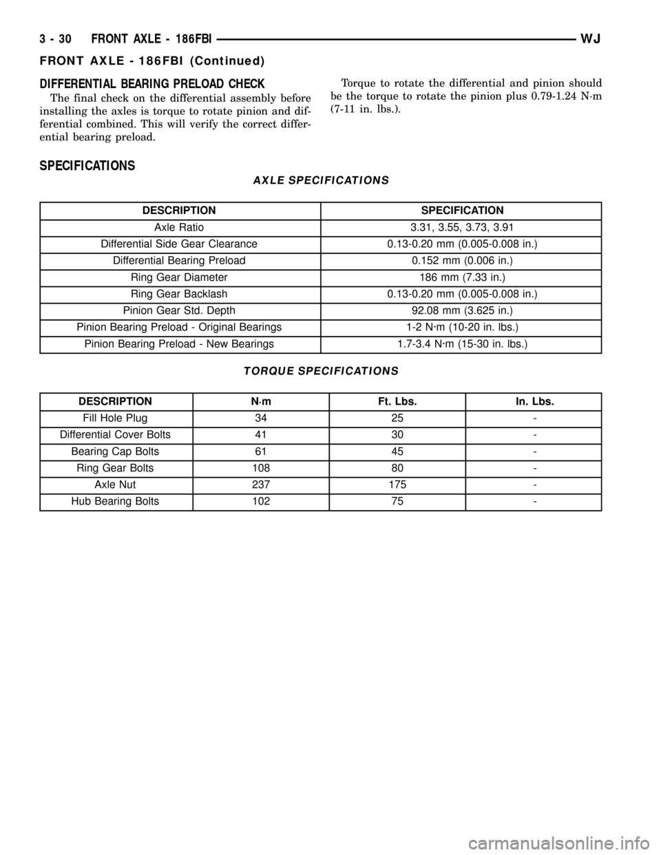
DIFFERENTIAL BEARING PRELOAD CHECK
The final check on the differential assembly before
installing the axles is torque to rotate pinion and dif-
ferential combined. This will verify the correct differ-
ential bearing preload.Torque to rotate the differential and pinion should
be the torque to rotate the pinion plus 0.79-1.24 N´m
(7-11 in. lbs.).
SPECIFICATIONS
AXLE SPECIFICATIONS
DESCRIPTION SPECIFICATION
Axle Ratio 3.31, 3.55, 3.73, 3.91
Differential Side Gear Clearance 0.13-0.20 mm (0.005-0.008 in.)
Differential Bearing Preload 0.152 mm (0.006 in.)
Ring Gear Diameter 186 mm (7.33 in.)
Ring Gear Backlash 0.13-0.20 mm (0.005-0.008 in.)
Pinion Gear Std. Depth 92.08 mm (3.625 in.)
Pinion Bearing Preload - Original Bearings 1-2 N´m (10-20 in. lbs.)
Pinion Bearing Preload - New Bearings 1.7-3.4 N´m (15-30 in. lbs.)
TORQUE SPECIFICATIONS
DESCRIPTION N´m Ft. Lbs. In. Lbs.
Fill Hole Plug 34 25 -
Differential Cover Bolts 41 30 -
Bearing Cap Bolts 61 45 -
Ring Gear Bolts 108 80 -
Axle Nut 237 175 -
Hub Bearing Bolts 102 75 -
3 - 30 FRONT AXLE - 186FBIWJ
FRONT AXLE - 186FBI (Continued)
Page 95 of 2199
REAR AXLE - 198RBI
TABLE OF CONTENTS
page page
REAR AXLE - 198RBI
DESCRIPTION.........................50
OPERATION...........................50
DIAGNOSIS AND TESTING................51
REMOVAL.............................55
INSTALLATION.........................56
ADJUSTMENTS........................56
SPECIFICATIONS.......................65
SPECIAL TOOLS.......................66
AXLE SHAFTS
REMOVAL.............................69
INSTALLATION.........................69
AXLE BEARINGS/SEALS
REMOVAL.............................69
INSTALLATION.........................70
PINION SEAL
REMOVAL.............................71
INSTALLATION.........................71
COLLAPSIBLE SPACER
REMOVAL.............................73INSTALLATION.........................73
DIFFERENTIAL
REMOVAL.............................75
DISASSEMBLY.........................77
ASSEMBLY............................77
INSTALLATION.........................77
DIFFERENTIAL-TRAC-LOC
DIAGNOSIS AND TESTING................79
DISASSEMBLY.........................79
CLEANING............................82
INSPECTION..........................82
ASSEMBLY............................82
DIFFERENTIAL CASE BEARINGS
REMOVAL.............................83
INSTALLATION.........................84
PINION GEAR/RING GEAR
REMOVAL.............................84
INSTALLATION.........................86
REAR AXLE - 198RBI
DESCRIPTION
The Rear Beam-design Iron (RBI) axle housing has
an iron center casting with axle shaft tubes extend-
ing from either side. The tubes are pressed into and
welded to the differential housing to form a one-piece
axle housing. The axles has semi-floating axle shafts,
meaning that loads are supported by the axle shaft
and bearings. The axle shafts are retained by bearing
retainer plates on the axles which are bolted to
flanges at the outboard end of the axle tubes.
The differential case is a one-piece design. Differ-
ential bearing preload and ring gear backlash is
adjusted by the use of selective spacer shims. Pinion
bearing preload is set and maintained by the use of a
collapsible spacer. A differential cover provides a
means for inspection and service.
Axles with optional Trac-Loktdifferential have a
one-piece differential case, and the same internal
components as a standard differential, plus two
clutch disc packs.
OPERATION
The axle receives power from the transmission/
transfer case through the rear propeller shaft. Therear propeller shaft is connected to the pinion gear
which rotates the differential through the gear mesh
with the ring gear bolted to the differential case. The
engine power is transmitted to the axle shafts
through the pinion mate and side gears. The side
gears are splined to the axle shafts.
STANDARD DIFFERENTIAL
During straight-ahead driving, the differential pin-
ion gears do not rotate on the pinion mate shaft. This
occurs because input torque applied to the gears is
divided and distributed equally between the two side
gears. As a result, the pinion gears revolve with the
pinion mate shaft but do not rotate around it (Fig. 1).
When turning corners, the outside wheel must
travel a greater distance than the inside wheel to
complete a turn. The difference must be compensated
for to prevent the tires from scuffing and skidding
through turns. To accomplish this, the differential
allows the axle shafts to turn at unequal speeds (Fig.
2). In this instance, the input torque applied to the
pinion gears is not divided equally. The pinion gears
now rotate around the pinion mate shaft in opposite
directions. This allows the side gear and axle shaft
attached to the outside wheel to rotate at a faster
speed.
3 - 50 REAR AXLE - 198RBIWJ
Page 110 of 2199

DIFFERENTIAL BEARING PRELOAD CHECK
The final check on the differential assembly before
installing the axles is torque to rotate pinion and dif-
ferential combined. This will verify the correct differ-
ential bearing preload.Torque to rotate the differential and pinion should
be the torque to rotate the pinion plus 0.79-1.24 N´m
(7-11 in. lbs.).
SPECIFICATIONS
AXLE SPECIFICATIONS
DESCRIPTION SPECIFICATION
Axle Ratio 3.07, 3.31, 3.55, 3.73, 4.11
Differential Bearing Preload 0.1 mm (0.004 in.)
Ring Gear Diameter 198 mm (7.795 in.)
Ring Gear Backlash 0.12-0.20 mm (0.005-0.008 in.)
Pinion Gear Std. Depth 96.85 mm (3.813 in.)
Pinion Bearing Preload - Original Bearings 1-2 N´m (10-20 in. lbs.)
Pinion Bearing Preload - New Bearings 1.7-3.9 N´m (15-35 in. lbs.)
TORQUE SPECIFICATIONS
DESCRIPTION N´m Ft. Lbs. In. Lbs.
Differential Cover Bolts 41 30 -
Bearing Cap Bolts 77 57 -
Ring Gear Bolts 129-142 95-105 -
Pinion Nut Minimum 272 200 -
Pinion Mate Shaft Screw 16.25 12 -
Axle Bearing Retainer Plate
Nuts61 45 -
WJREAR AXLE - 198RBI 3 - 65
REAR AXLE - 198RBI (Continued)
Page 135 of 2199

REAR AXLE - 226RBA
TABLE OF CONTENTS
page page
REAR AXLE - 226RBA
DESCRIPTION.........................90
OPERATION...........................90
DIAGNOSIS AND TESTING................92
REMOVAL.............................95
INSTALLATION.........................96
ADJUSTMENTS........................97
SPECIFICATIONS......................105
SPECIAL TOOLS.......................106
AXLE SHAFTS
REMOVAL............................109
INSTALLATION........................109
AXLE BEARINGS/SEALS
REMOVAL............................109
INSTALLATION........................110
PINION SEAL
REMOVAL............................111
INSTALLATION........................112
COLLAPSIBLE SPACER
REMOVAL............................113INSTALLATION........................114
DIFFERENTIAL
REMOVAL............................115
DISASSEMBLY........................117
ASSEMBLY...........................117
INSTALLATION........................117
DIFFERENTIAL - TRAC-LOK
DIAGNOSIS AND TESTING...............119
DISASSEMBLY........................119
CLEANING...........................121
INSPECTION.........................121
ASSEMBLY...........................121
DIFFERENTIAL CASE BEARINGS
REMOVAL............................123
INSTALLATION........................123
PINION GEAR/RING GEAR
REMOVAL............................124
INSTALLATION........................126
REAR AXLE - 226RBA
DESCRIPTION
The Rear Beam-design Aluminum (RBA) axle hous-
ing has an aluminum center casting (differential
housing) with axle shaft tubes extending from either
side. The tubes are pressed into the differential hous-
ing to form a one-piece axle housing. The axle has
semi-floating axle shafts, meaning that vehicle load
is supported by the axle shaft and bearings.
The differential case is a one-piece design. Differen-
tial bearing preload and ring gear backlash is adjusted
with selective shims. Pinion bearing preload is set and
maintained by the use of a collapsible spacer. The cover
provides a means for inspection and service.
Optional Trac-Loktdifferential differential has a
one-piece differential case, and the same internal
components as a standard differential, plus two
clutch disc packs.
Optional Vari-Loktdifferential has a one-piece dif-
ferential case which contains the gerotor pump
assembly and the clutch mechinism. The unit is ser-
viced only as an assembly.
OPERATION
The axle receives power from the transfer case
through the front propeller shaft. The front propellershaft is connected to the pinion gear which rotates
the differential through the gear mesh with the ring
gear bolted to the differential case. The engine power
is transmitted to the axle shafts through the pinion
mate and side gears. The side gears are splined to
the axle shafts.
STANDARD DIFFERENTIAL
During straight-ahead driving the differential pin-
ion gears do not rotate on the pinion mate shaft. This
occurs because input torque applied to the gears is
divided and distributed equally between the two side
gears. As a result, the pinion gears revolve with the
pinion mate shaft but do not rotate around it (Fig. 1).
When turning corners, the outside wheel must travel
a greater distance than the inside wheel to complete a
turn. The difference must be compensated for to prevent
the tires from scuffing and skidding through turns. To
accomplish this, the differential allows the axle shafts
to turn at unequal speeds (Fig. 2). In this instance, the
input torque applied to the pinion gears is not divided
equally. The pinion gears now rotate around the pinion
mate shaft in opposite directions. This allows the side
gear and axle shaft attached to the outside wheel to
rotate at a faster speed.
3 - 90 REAR AXLE - 226RBAWJ
Page 150 of 2199
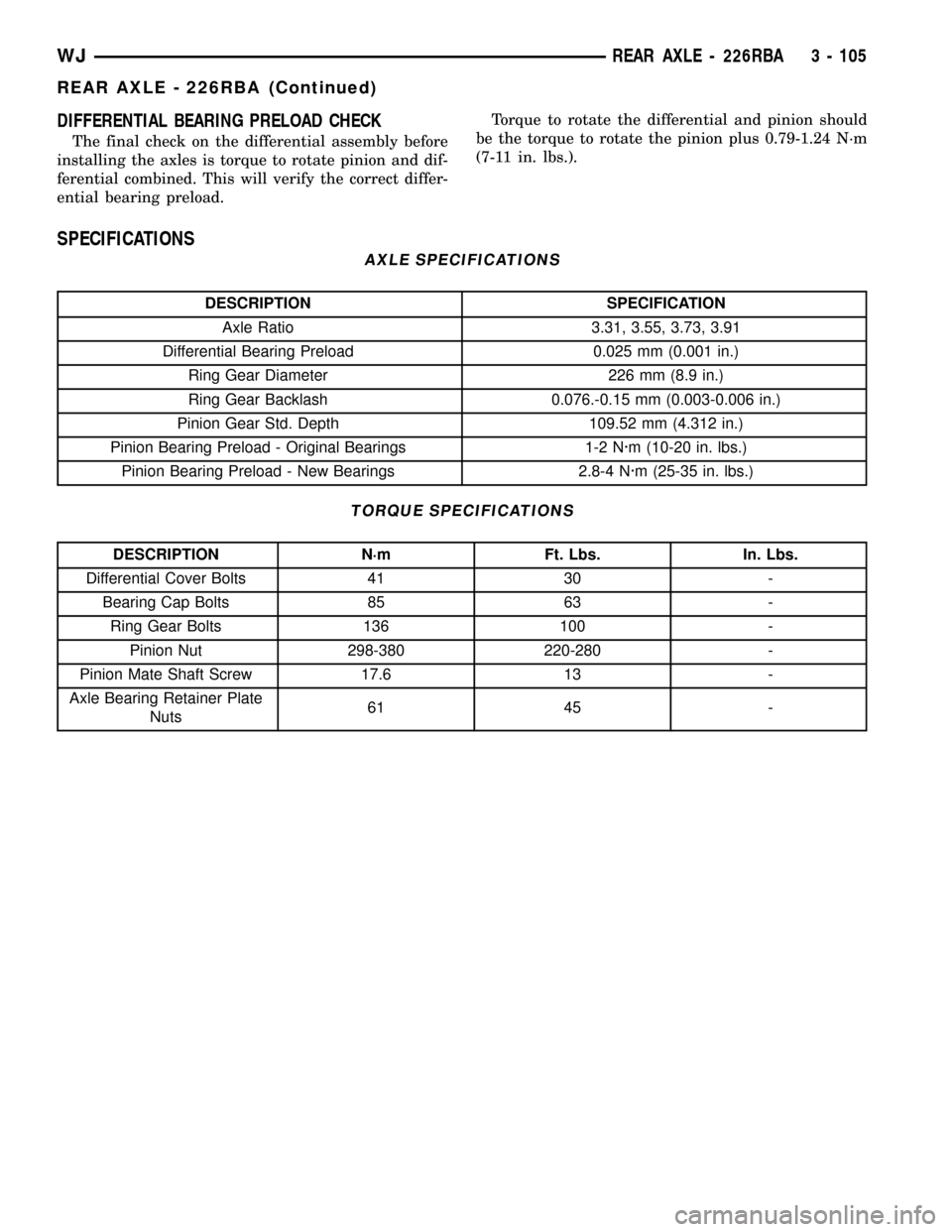
DIFFERENTIAL BEARING PRELOAD CHECK
The final check on the differential assembly before
installing the axles is torque to rotate pinion and dif-
ferential combined. This will verify the correct differ-
ential bearing preload.Torque to rotate the differential and pinion should
be the torque to rotate the pinion plus 0.79-1.24 N´m
(7-11 in. lbs.).
SPECIFICATIONS
AXLE SPECIFICATIONS
DESCRIPTION SPECIFICATION
Axle Ratio 3.31, 3.55, 3.73, 3.91
Differential Bearing Preload 0.025 mm (0.001 in.)
Ring Gear Diameter 226 mm (8.9 in.)
Ring Gear Backlash 0.076.-0.15 mm (0.003-0.006 in.)
Pinion Gear Std. Depth 109.52 mm (4.312 in.)
Pinion Bearing Preload - Original Bearings 1-2 N´m (10-20 in. lbs.)
Pinion Bearing Preload - New Bearings 2.8-4 N´m (25-35 in. lbs.)
TORQUE SPECIFICATIONS
DESCRIPTION N´m Ft. Lbs. In. Lbs.
Differential Cover Bolts 41 30 -
Bearing Cap Bolts 85 63 -
Ring Gear Bolts 136 100 -
Pinion Nut 298-380 220-280 -
Pinion Mate Shaft Screw 17.6 13 -
Axle Bearing Retainer Plate
Nuts61 45 -
WJREAR AXLE - 226RBA 3 - 105
REAR AXLE - 226RBA (Continued)
Page 176 of 2199
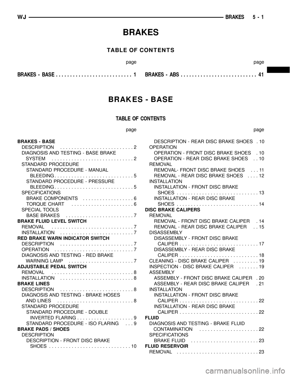
BRAKES
TABLE OF CONTENTS
page page
BRAKES - BASE........................... 1BRAKES - ABS........................... 41
BRAKES - BASE
TABLE OF CONTENTS
page page
BRAKES - BASE
DESCRIPTION..........................2
DIAGNOSIS AND TESTING - BASE BRAKE
SYSTEM.............................2
STANDARD PROCEDURE
STANDARD PROCEDURE - MANUAL
BLEEDING............................5
STANDARD PROCEDURE - PRESSURE
BLEEDING............................5
SPECIFICATIONS
BRAKE COMPONENTS..................6
TORQUE CHART......................6
SPECIAL TOOLS
BASE BRAKES........................7
BRAKE FLUID LEVEL SWITCH
REMOVAL.............................7
INSTALLATION..........................7
RED BRAKE WARN INDICATOR SWITCH
DESCRIPTION..........................7
OPERATION............................7
DIAGNOSIS AND TESTING - RED BRAKE
WARNING LAMP.......................7
ADJUSTABLE PEDAL SWITCH
REMOVAL.............................8
INSTALLATION..........................8
BRAKE LINES
DESCRIPTION..........................8
DIAGNOSIS AND TESTING - BRAKE HOSES
AND LINES...........................8
STANDARD PROCEDURE
STANDARD PROCEDURE - DOUBLE
INVERTED FLARING....................9
STANDARD PROCEDURE - ISO FLARING . . . 9
BRAKE PADS / SHOES
DESCRIPTION
DESCRIPTION - FRONT DISC BRAKE
SHOES.............................10DESCRIPTION - REAR DISC BRAKE SHOES . 10
OPERATION
OPERATION - FRONT DISC BRAKE SHOES . 10
OPERATION - REAR DISC BRAKE SHOES . . 10
REMOVAL
REMOVAL- FRONT DISC BRAKE SHOES . . . 11
REMOVAL - REAR DISC BRAKE SHOES....12
INSTALLATION
INSTALLATION - FRONT DISC BRAKE
SHOES.............................13
INSTALLATION - REAR DISC BRAKE
SHOES.............................14
DISC BRAKE CALIPERS
REMOVAL
REMOVAL - FRONT DISC BRAKE CALIPER . 14
REMOVAL - REAR DISC BRAKE CALIPER . . 15
DISASSEMBLY
DISASSEMBLY - FRONT DISC BRAKE
CALIPER............................17
DISASSEMBLY - REAR DISC BRAKE
CALIPER............................18
CLEANING - DISC BRAKE CALIPER.........19
INSPECTION - DISC BRAKE CALIPER.......19
ASSEMBLY
ASSEMBLY - FRONT DISC BRAKE CALIPER . 20
ASSEMBLY - REAR DISC BRAKE CALIPER . 21
INSTALLATION
INSTALLATION - FRONT DISC BRAKE
CALIPER............................22
INSTALLATION - REAR DISC BRAKE
CALIPER............................22
FLUID
DIAGNOSIS AND TESTING - BRAKE FLUID
CONTAMINATION.....................22
SPECIFICATIONS
BRAKE FLUID........................23
FLUID RESERVOIR
REMOVAL.............................23
WJBRAKES 5 - 1
Page 181 of 2199
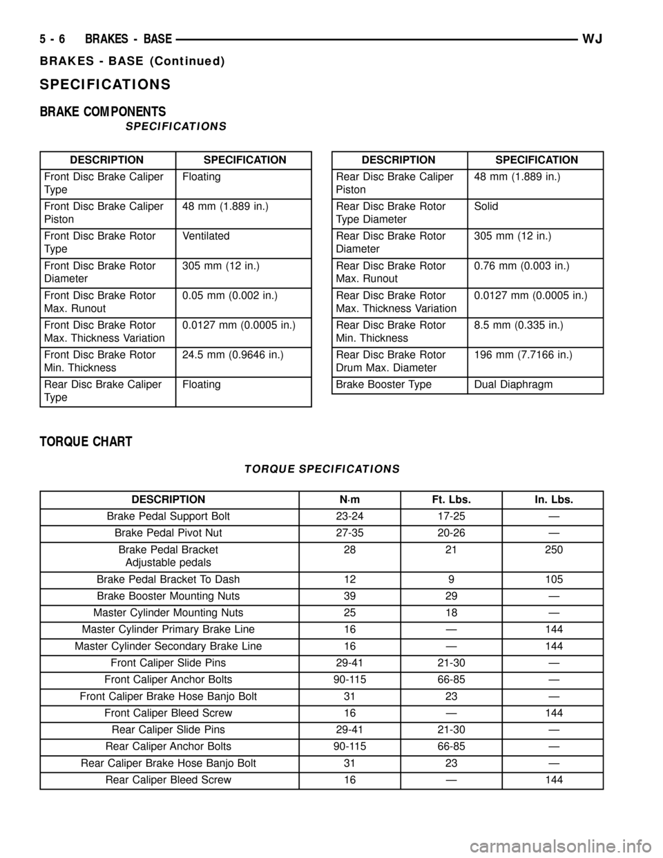
SPECIFICATIONS
BRAKE COMPONENTS
SPECIFICATIONS
DESCRIPTION SPECIFICATION
Front Disc Brake Caliper
TypeFloating
Front Disc Brake Caliper
Piston48 mm (1.889 in.)
Front Disc Brake Rotor
TypeVentilated
Front Disc Brake Rotor
Diameter305 mm (12 in.)
Front Disc Brake Rotor
Max. Runout0.05 mm (0.002 in.)
Front Disc Brake Rotor
Max. Thickness Variation0.0127 mm (0.0005 in.)
Front Disc Brake Rotor
Min. Thickness24.5 mm (0.9646 in.)
Rear Disc Brake Caliper
TypeFloatingDESCRIPTION SPECIFICATION
Rear Disc Brake Caliper
Piston48 mm (1.889 in.)
Rear Disc Brake Rotor
Type DiameterSolid
Rear Disc Brake Rotor
Diameter305 mm (12 in.)
Rear Disc Brake Rotor
Max. Runout0.76 mm (0.003 in.)
Rear Disc Brake Rotor
Max. Thickness Variation0.0127 mm (0.0005 in.)
Rear Disc Brake Rotor
Min. Thickness8.5 mm (0.335 in.)
Rear Disc Brake Rotor
Drum Max. Diameter196 mm (7.7166 in.)
Brake Booster Type Dual Diaphragm
TORQUE CHART
TORQUE SPECIFICATIONS
DESCRIPTION N´m Ft. Lbs. In. Lbs.
Brake Pedal Support Bolt 23-24 17-25 Ð
Brake Pedal Pivot Nut 27-35 20-26 Ð
Brake Pedal Bracket
Adjustable pedals28 21 250
Brake Pedal Bracket To Dash 12 9 105
Brake Booster Mounting Nuts 39 29 Ð
Master Cylinder Mounting Nuts 25 18 Ð
Master Cylinder Primary Brake Line 16 Ð 144
Master Cylinder Secondary Brake Line 16 Ð 144
Front Caliper Slide Pins 29-41 21-30 Ð
Front Caliper Anchor Bolts 90-115 66-85 Ð
Front Caliper Brake Hose Banjo Bolt 31 23 Ð
Front Caliper Bleed Screw 16 Ð 144
Rear Caliper Slide Pins 29-41 21-30 Ð
Rear Caliper Anchor Bolts 90-115 66-85 Ð
Rear Caliper Brake Hose Banjo Bolt 31 23 Ð
Rear Caliper Bleed Screw 16 Ð 144
5 - 6 BRAKES - BASEWJ
BRAKES - BASE (Continued)