2002 JEEP GRAND CHEROKEE lower control arm
[x] Cancel search: lower control armPage 44 of 2199

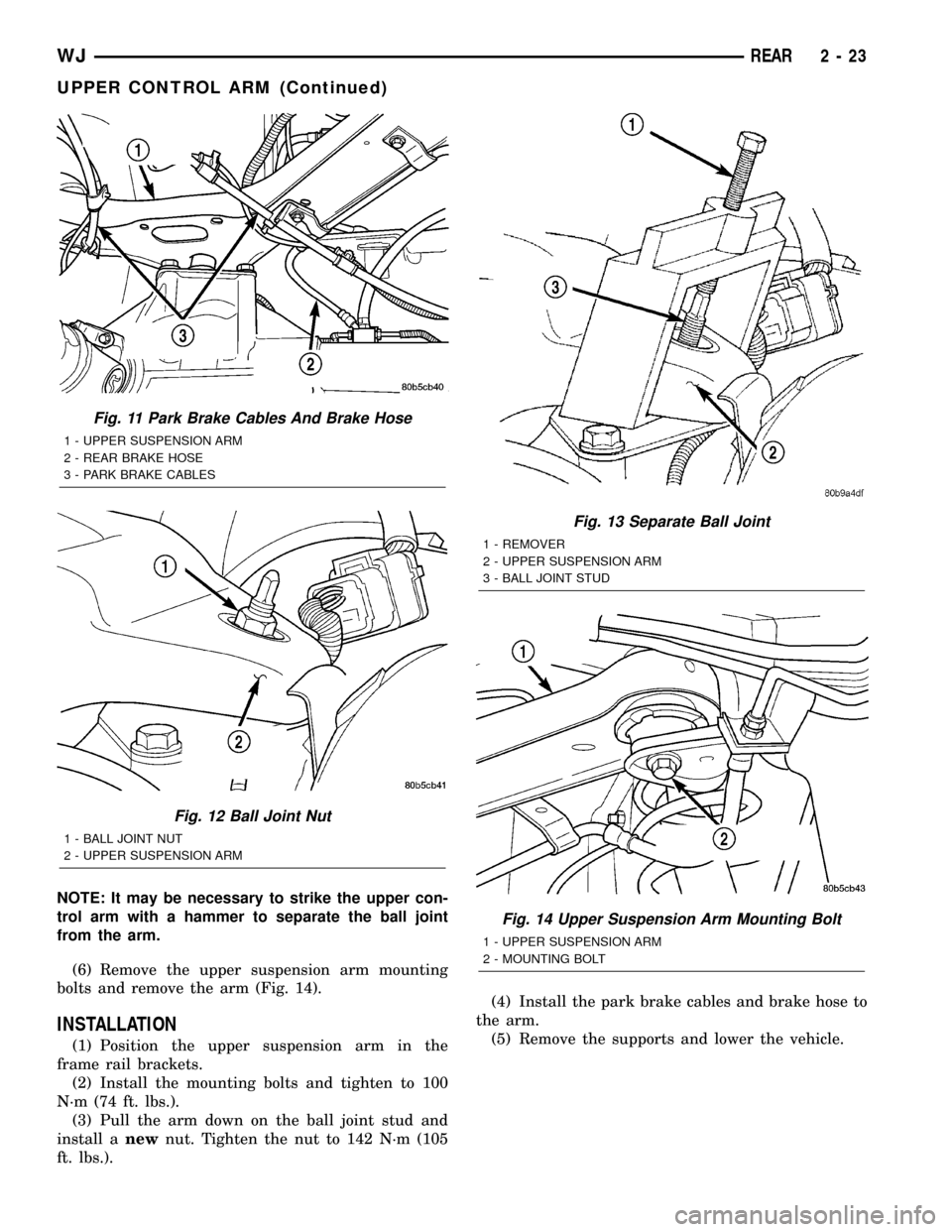
NOTE: It may be necessary to strike the upper con-
trol arm with a hammer to separate the ball joint
from the arm.
(6) Remove the upper suspension arm mounting
bolts and remove the arm (Fig. 14).
INSTALLATION
(1) Position the upper suspension arm in the
frame rail brackets.
(2) Install the mounting bolts and tighten to 100
N´m (74 ft. lbs.).
(3) Pull the arm down on the ball joint stud and
install anewnut. Tighten the nut to 142 N´m (105
ft. lbs.).(4) Install the park brake cables and brake hose to
the arm.
(5) Remove the supports and lower the vehicle.
Fig. 11 Park Brake Cables And Brake Hose
1 - UPPER SUSPENSION ARM
2 - REAR BRAKE HOSE
3 - PARK BRAKE CABLES
Fig. 12 Ball Joint Nut
1 - BALL JOINT NUT
2 - UPPER SUSPENSION ARM
Fig. 13 Separate Ball Joint
1 - REMOVER
2 - UPPER SUSPENSION ARM
3 - BALL JOINT STUD
Fig. 14 Upper Suspension Arm Mounting Bolt
1 - UPPER SUSPENSION ARM
2 - MOUNTING BOLT
WJREAR 2 - 23
UPPER CONTROL ARM (Continued)
Page 116 of 2199

(7) Press metal retaining ring onto axle shaft with
Installer 7913 and a press (Fig. 30).
(8) Install axle in vehicle.
PINION SEAL
REMOVAL
(1) Raise and support the vehicle.
(2) Remove wheel and tire assemblies.
(3) Remove brake calipers and rotors.
(4) Mark propeller shaft and pinion yoke for
installation reference.
(5) Remove propeller shaft from the yoke.
(6) Rotate pinion gear a minimum of ten times and
verify pinion rotates smoothly.
(7) Record rotating torque of the pinion gear with
an inch pound dial-type torque wrench, for installa-
tion reference.
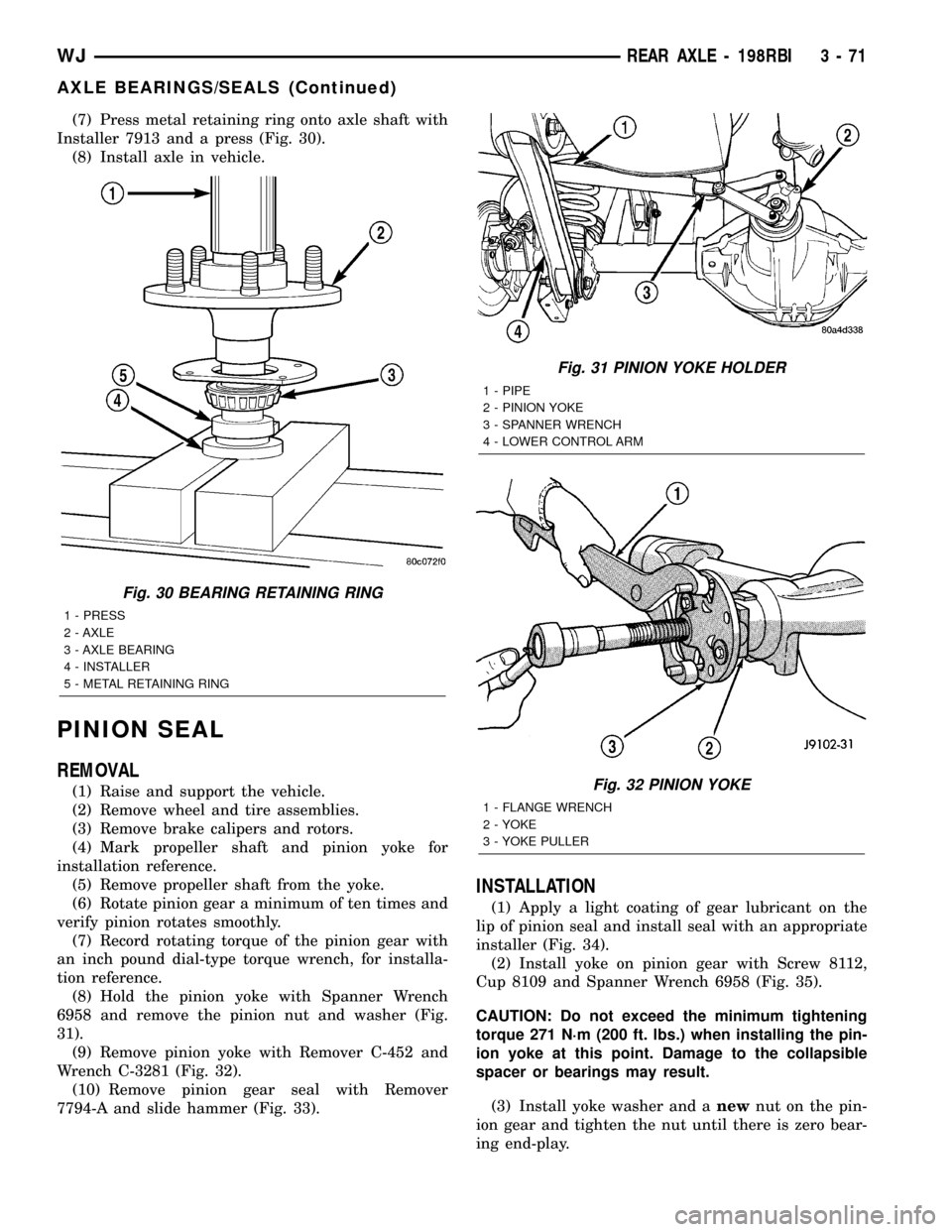
(8) Hold the pinion yoke with Spanner Wrench
6958 and remove the pinion nut and washer (Fig.
31).
(9) Remove pinion yoke with Remover C-452 and
Wrench C-3281 (Fig. 32).
(10) Remove pinion gear seal with Remover
7794-A and slide hammer (Fig. 33).
INSTALLATION
(1) Apply a light coating of gear lubricant on the
lip of pinion seal and install seal with an appropriate
installer (Fig. 34).
(2) Install yoke on pinion gear with Screw 8112,
Cup 8109 and Spanner Wrench 6958 (Fig. 35).
CAUTION: Do not exceed the minimum tightening
torque 271 N´m (200 ft. lbs.) when installing the pin-
ion yoke at this point. Damage to the collapsible
spacer or bearings may result.
(3) Install yoke washer and anewnut on the pin-
ion gear and tighten the nut until there is zero bear-
ing end-play.
Fig. 30 BEARING RETAINING RING
1 - PRESS
2 - AXLE
3 - AXLE BEARING
4 - INSTALLER
5 - METAL RETAINING RING
Fig. 31 PINION YOKE HOLDER
1 - PIPE
2 - PINION YOKE
3 - SPANNER WRENCH
4 - LOWER CONTROL ARM
Fig. 32 PINION YOKE
1 - FLANGE WRENCH
2 - YOKE
3 - YOKE PULLER
WJREAR AXLE - 198RBI 3 - 71
AXLE BEARINGS/SEALS (Continued)
Page 118 of 2199

(6) If the rotating torque is low, use Spanner
Wrench 6958 to hold the pinion yoke (Fig. 37), and
tighten the pinion nut in 6.8 N´m (5 ft. lbs.) incre-
ments until the proper rotating torque is achieved.
CAUTION: If maximum tightening torque is reached
prior to reaching required rotating torque, the col-
lapsible spacer may have been damaged. Replace
the collapsible spacer.
(7) Install the propeller shaft with reference marks
aligned.
(8) Add gear lubricant to the differential if neces-
sary.
(9) Install brake rotors and calipers.
(10) Install wheel and tire assemblies.
(11) Lower the vehicle.
COLLAPSIBLE SPACER
REMOVAL
(1) Raise and support the vehicle.
(2) Remove wheel and tire assemblies.
(3) Remove rear brake calipers and rotors.
(4) Mark propeller shaft and pinion yoke for
installation reference and remove propeller shaft.
(5) Rotate pinion gear a minimum of ten times and
verify pinion rotates smoothly.
(6) Record rotate torque of the pinion gear, with an
inch pound torque wrench.
(7) Hold pinion yoke with Spanner Wrench 6958
and remove pinion nut and washer (Fig. 38).
(8) Remove pinion yoke with Remover C-452 and
Wrench C-3281 (Fig. 39).(9) Remove pinion shaft seal with Remover 7794-A
and slide hammer (Fig. 40).
(10) Remove front pinion bearing using a pair of
pick tools to pull the bearing off the pinion gear
shaft.
NOTE: If the pinion bearing becomes bound on the
pinion shaft, lightly tap the end of the shaft with a
rawhide/rubber mallet.
(11) Remove the collapsible spacer.
INSTALLATION
(1) Install anewcollapsible spacer on pinion
shaft.
(2) Install pinion front bearing on the pinion shaft.
Fig. 37 PINION SHAFT NUT
1 - SPANNER WRENCH
2 - PIPE
3 - TORQUE WRENCH
Fig. 38 PINION YOKE HOLDER
1 - 1 in. PIPE
2 - PINION YOKE
3 - SPANNER WRENCH
4 - LOWER CONTROL ARM
Fig. 39 PINION YOKE PULLER
1 - WRENCH
2 - PINION YOKE
3 - PULLER
WJREAR AXLE - 198RBI 3 - 73
PINION SEAL (Continued)
Page 129 of 2199

INSTALLATION
NOTE: If differential side bearings or differential
case are replaced, differential side bearing shim
requirements may change. Refer to Adjustments
(Differential Bearing Preload and Gear Backlash) for
procedures.
(1) Install differential side bearings with Installer
C-3716-A and Handle C-4171 (Fig. 70).
(2) Install differential in axle housing.
(3) Remove support and lower vehicle.
PINION GEAR/RING GEAR
REMOVAL
NOTE: The ring and pinion gears are serviced as a
matched set. Never replace one gear without the
other gear.
(1) Raise and support vehicle.
(2) Mark pinion yoke and propeller shaft for
installation reference.
(3) Disconnect propeller shaft from pinion yoke
and tie shaft to underbody.
(4) Remove differential from the housing.
(5) Place differential case in a vise with soft metal
jaw.(6) Remove bolts holding ring gear to differential
case.
(7) Drive ring gear from differential case with a
rawhide hammer (Fig. 71).
(8) Hold the pinion yoke with Spanner Wrench
6958 and remove the pinion yoke nut and washer
(Fig. 72).
Fig. 70 Differential Side Bearing
1 - INSTALLER
2 - HANDLE
Fig. 71 RING GEAR
1 - DIFFERENTIAL CASE
2 - RING GEAR
3 - HAMMER
Fig. 72 PINION YOKE HOLDER
1 - 1 in. PIPE
2 - PINION YOKE
3 - HOLDER
4 - LOWER CONTROL ARM
3 - 84 REAR AXLE - 198RBIWJ
DIFFERENTIAL CASE BEARINGS (Continued)
Page 156 of 2199

(7) Press metal retaining ring onto axle shaft with
Installer 7913 and a press (Fig. 30).
(8) Install axle in vehicle.
PINION SEAL
REMOVAL
(1) Raise and support the vehicle.
(2) Remove wheel and tire assemblies.
(3) Remove rear brake calipers and rotors.
(4) Mark propeller shaft and pinion yoke for
installation reference.
(5) Remove the propeller shaft from the yoke.
(6) Rotate pinion gear three or four times and ver-
ify that pinion rotates smoothly.
(7) Record torque necessary to rotate the pinion
gear with a inch pound dial-type torque wrench.
(8) Using a short piece of pipe and Spanner
Wrench 6958 to hold the pinion yoke and remove pin-
ion nut and washer (Fig. 31).
(9) Remove pinion companion flange with Remover
C-452 and Flange Wrench C-3281. (Fig. 32)
Fig. 30 BEARING RETAINING RING
1 - PRESS
2 - AXLE
3 - AXLE BEARING
4 - INSTALLER
5 - METAL RETAINING RING
Fig. 31 Pinion Yoke Holder
1 - PIPE
2 - PINION YOKE
3 - SPANNER WRENCH
4 - LOWER CONTROL ARM
Fig. 32 Pinion Yoke Remover
1 - FLANGE WRENCH
2 - YOKE
3 - YOKE PULLER
WJREAR AXLE - 226RBA 3 - 111
AXLE BEARINGS/SEALS (Continued)
Page 158 of 2199

(5) If rotating torque is low, use Wrench 6958 to
hold the pinion yoke (Fig. 37) and tighten the pinion
shaft nut in 6.8 N´m (5 ft. lbs.) increments until
rotating torque is achieved.
CAUTION: If the maximum tightening torque is
reached prior to reaching the required rotating
torque, the collapsible spacer may have been dam-
aged. Replace the collapsible spacer.
(6) Install propeller shaft with reference marks
aligned.
(7) Fill differential with gear lubricant.
(8) Install the brake rotors and calipers.
(9) Install wheel and tire assemblies.
(10) Lower the vehicle.
COLLAPSIBLE SPACER
REMOVAL
(1) Raise and support the vehicle.
(2) Remove wheel and tire assemblies.
(3) Remove rear brake calipers and rotors.
(4) Mark propeller shaft and pinion yoke for
installation reference and remove propeller shaft.
(5) Rotate pinion gear a minimum of ten times and
verify pinion rotates smoothly.
(6) Record rotate torque of the pinion gear, with an
inch pound torque wrench.
(7) Hold pinion yoke with Spanner Wrench 6958
and remove pinion nut and washer (Fig. 38).
(8) Remove pinion yoke with Remover C-452 and
Wrench C-3281 (Fig. 39).
Fig. 37 PINION SHAFT NUT
1 - SPANNER WRENCH
2 - PIPE
3 - TORQUE WRENCH
Fig. 38 PINION YOKE HOLDER
1 - 1 in. PIPE
2 - PINION YOKE
3 - SPANNER WRENCH
4 - LOWER CONTROL ARM
Fig. 39 PINION YOKE PULLER
1 - WRENCH
2 - PINION YOKE
3 - PULLER
WJREAR AXLE - 226RBA 3 - 113
PINION SEAL (Continued)
Page 169 of 2199

CAUTION: Vari-lokTplenum must be seated against
the differential case prior to installing the ring gear
side differential bearing.
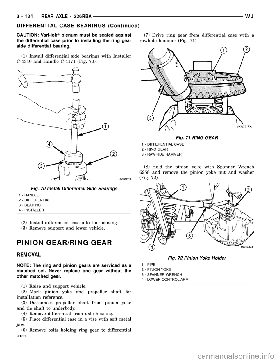
(1) Install differential side bearings with Installer
C-4340 and Handle C-4171 (Fig. 70).
(2) Install differential case into the housing.
(3) Remove support and lower vehicle.
PINION GEAR/RING GEAR
REMOVAL
NOTE: The ring and pinion gears are serviced as a
matched set. Never replace one gear without the
other matched gear.
(1) Raise and support vehicle.
(2) Mark pinion yoke and propeller shaft for
installation reference.
(3) Disconnect propeller shaft from pinion yoke
and tie shaft to underbody.
(4) Remove differential from axle housing.
(5) Place differential case in a vise with soft metal
jaw.
(6) Remove bolts holding ring gear to differential
case.(7) Drive ring gear from differential case with a
rawhide hammer (Fig. 71).
(8) Hold the pinion yoke with Spanner Wrench
6958 and remove the pinion yoke nut and washer
(Fig. 72).
Fig. 70 Install Differential Side Bearings
1 - HANDLE
2 - DIFFERENTIAL
3 - BEARING
4 - INSTALLER
Fig. 71 RING GEAR
1 - DIFFERENTIAL CASE
2 - RING GEAR
3 - RAWHIDE HAMMER
Fig. 72 Pinion Yoke Holder
1 - PIPE
2 - PINION YOKE
3 - SPANNER WRENCH
4 - LOWER CONTROL ARM
3 - 124 REAR AXLE - 226RBAWJ
DIFFERENTIAL CASE BEARINGS (Continued)
Page 235 of 2199

accessory drive belt (Refer to 7 - COOLING/ACCES-
SORY DRIVE/DRIVE BELTS - REMOVAL).
Add coolant to radiator to bring level to within 6.3
mm (1/4 in) of top of thermostat housing.
CAUTION: Avoid overheating. Do not operate
engine for an excessive period of time. Open drain-
cock immediately after test to eliminate boil over.
Start engine and accelerate rapidly three times, to
approximately 3000 rpm while observing coolant. If
internal engine combustion gases are leaking into
cooling system, bubbles will appear in coolant. If bub-
bles do not appear, internal combustion gas leakage
is not present.
DIAGNOSIS AND TESTING - COOLING SYSTEM
DEAERATION
As the engine operates, any air trapped in cooling
system gathers under the radiator cap. The next time
the engine is operated, thermal expansion of coolant
will push any trapped air past radiator cap into the
coolant reserve/overflow tank. Here it escapes to the
atmosphere into the tank. When the engine cools
down the coolant, it will be drawn from the reserve/
overflow tank into the radiator to replace any
removed air.
STANDARD PROCEDURE
STANDARD PROCEDUREÐDRAINING COOLING
SYSTEM 4.7L ENGINE
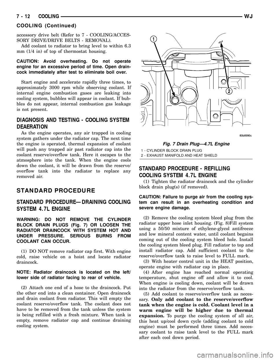
WARNING: DO NOT REMOVE THE CYLINDER
BLOCK DRAIN PLUGS (Fig. 7) OR LOOSEN THE
RADIATOR DRAINCOCK WITH SYSTEM HOT AND
UNDER PRESSURE. SERIOUS BURNS FROM
COOLANT CAN OCCUR.
(1) DO NOT remove radiator cap first. With engine
cold, raise vehicle on a hoist and locate radiator
draincock.
NOTE: Radiator draincock is located on the left/
lower side of radiator facing to rear of vehicle.
(2) Attach one end of a hose to the draincock. Put
the other end into a clean container. Open draincock
and drain coolant from radiator. This will empty the
coolant reserve/overflow tank. The coolant does not
have to be removed from the tank unless the system
is being refilled with a fresh mixture. When tank is
empty, remove radiator cap and continue draining
cooling system.
STANDARD PROCEDURE - REFILLING
COOLING SYSTEM 4.7L ENGINE
(1) Tighten the radiator draincock and the cylinder
block drain plug(s) (if removed).
CAUTION: Failure to purge air from the cooling sys-
tem can result in an overheating condition and
severe engine damage.
(2) Remove the cooling system bleed plug from the
radiator upper hose inlet housing. (Fig. 8)Fill system
using a 50/50 mixture of ethylene-glycol antifreeze
and low mineral content water, until coolant begains
coming out of the cooling system bleed hole. Install
the cooling system bleed plug. Fill radiator to top and
install radiator cap. Add sufficient coolant to the
reserve/overflow tank to raise level to FULL mark.
(3) With heater control unit in the HEAT position,
operate engine with radiator cap in place.
(4) After engine has reached normal operating
temperature, shut engine off and allow it to cool.
When engine is cooling down, coolant will be drawn
into the radiator from the reserve/overflow tank.
(5) Add coolant to reserve/overflow tank as neces-
sary.Only add coolant to the reserve/overflow
tank when the engine is cold. Coolant level in a
warm engine will be higher due to thermal
expansion.To purge the cooling system of all air,
this heat up/cool down cycle (adding coolant to cold
engine) must be performed three times. Add neces-
sary coolant to raise tank level to the FULL mark
after each cool down period.
Fig. 7 Drain PlugÐ4.7L Engine
1 - CYLINDER BLOCK DRAIN PLUG
2 - EXHAUST MANIFOLD AND HEAT SHIELD
7 - 12 COOLINGWJ
COOLING (Continued)