2002 JEEP GRAND CHEROKEE filter
[x] Cancel search: filterPage 404 of 2199

(6) While pulling assembly from engine, note direc-
tion and position of pulse ring (Fig. 6). After removal,
look down into top of oil pump and note direction and
position of slot at top of oil pump gear.
(7) Remove and discard old oil pump drive-to-en-
gine block gasket.
REMOVAL - 4.7L
The Camshaft Position Sensor (CMP) on the 4.7L
V±8 engine is bolted to the front/top of the right cyl-
inder head (Fig. 10).
It is easier to remove/install sensor from under
vehicle.
(1) Raise and support vehicle.
(2) Disconnect electrical connector at CMP sensor
(Fig. 10).
(3) Remove sensor mounting bolt (Fig. 10).
(4) Carefully pry sensor from cylinder head in a
rocking action with two small screwdrivers.Some
4.7L engines are equipped with a sensor spacer
shim. If equipped, this shim will be located at
sensor bolt hole between cylinder head and
sensor mounting tang (TSB W08±18±00). Save
this shim for sensor installation.
(5) Check condition of sensor o-ring.
Fig. 7 CMP Location - 4.0L Engine
1 - OIL FILTER
2 - CAMSHAFT POSITION SENSOR
3 - CLAMP BOLT
4 - HOLD-DOWN CLAMP
5 - MOUNTING BOLTS (2)
6 - ELEC. CONNECTOR
Fig. 8 CMP Pulse Ring Alignment - 4.0L Engine
1 - PULSE RING (SHUTTER)
2 - TOOTHPICK
3 - SENSOR BASE (OIL PUMP DRIVESHAFT ASSEMBLY)
Fig. 9 Align Timing Marks - 4.0L Engine
1 - CRANKSHAFT VIBRATION DAMPER TIMING MARK
WJIGNITION CONTROL 8I - 7
CAMSHAFT POSITION SENSOR (Continued)
Page 405 of 2199

INSTALLATION
INSTALLATION - 4.0L
SENSOR ONLY - 4.0L
The Camshaft Position Sensor (CMP) on the 4.0L
6±cylinder engine is bolted to the top of the oil pump
drive shaft assembly (Fig. 6). The sensor and drive
shaft assembly is located on the right side of the
engine near the oil filter (Fig. 7).
(1) Install sensor to oil pump drive.
(2) Install 2 sensor mounting bolts and tighten to
2 N´m (15 in. lbs.) torque.
(3) Connect electrical connector to CMP sensor.
OIL PUMP DRIVE AND SENSOR - 4.0L
(1) Clean oil pump drive mounting hole area of
engine block.
(2) Install new oil pump drive-to-engine block gas-
ket.
(3) Temporarily install a toothpick or similar tool
through access hole at side of oil pump drive housing.
Align toothpick into mating hole on pulse ring (Fig.
8).(4) Install oil pump drive into engine while align-
ing into slot on oil pump. Rotate oil pump drive back
to its original position and install hold-down clamp
and bolt. Finger tighten bolt. Do not do a final tight-
ening of bolt at this time.
(5) If engine crankshaft or camshaft has been
rotated, such as during engine tear-down, CMP sen-
sor relationship must be reestablished.
(a) Remove ignition coil rail assembly. Refer to
Ignition Coil Removal/Installation.
(b) Remove cylinder number 1 spark plug.
(c) Hold a finger over the open spark plug hole.
Rotate engine at vibration dampener bolt until
compression (pressure) is felt.
(d) Slowly continue to rotate engine. Do this
until timing index mark on vibration damper pul-
ley aligns with top dead center (TDC) mark (0
degree) on timing degree scale (Fig. 9). Always
rotate engine in direction of normal rotation. Do
not rotate engine backward to align timing marks.
(e) Install oil pump drive into engine while
aligning into slot on oil pump. If pump drive will
not drop down flush to engine block, the oil pump
slot is not aligned. Remove oil pump drive and
align slot in oil pump to shaft at bottom of drive.
Install into engine. Rotate oil pump drive back to
its original position and install hold-down clamp
and bolt. Finger tighten bolt. Do not do a final
tightening of bolt at this time.
(f) Remove toothpick from housing.
(6) Install sensor to oil pump drive. After installa-
tion, the CMP sensor should face rear of engine 0É.
(7) Install 2 sensor mounting bolts and tighten to
2 N´m (15 in. lbs.) torque.
(8) Connect electrical connector to CMP sensor.
(9) If removed, install spark plug and ignition coil
rail.
To verify correct rotational position of oil pump
drive, the DRB scan tool must be used.
WARNING: WHEN PERFORMING THE FOLLOWING
TEST, THE ENGINE WILL BE RUNNING. BE CARE-
FUL NOT TO STAND IN LINE WITH THE FAN
BLADES OR FAN BELT. DO NOT WEAR LOOSE
CLOTHING.
(10) Connect DRB scan tool to data link connector.
The data link connector is located in passenger com-
partment, below and to left of steering column.
(11) Gain access to SET SYNC screen on DRB.
(12) Follow directions on DRB screen and start
engine. Bring to operating temperature (engine must
be in ªclosed loopº mode).
(13) With engine running atidle speed, the words
IN RANGE should appear on screen along with 0É.
This indicates correct position of oil pump drive.
Fig. 10 CMP LocationÐ4.7L Engine
1 - RIGHT CYLINDER HEAD
2 - CAMSHAFT POSITION SENSOR
3 - MOUNTING BOLT
4 - ELEC. CONNECTOR
8I - 8 IGNITION CONTROLWJ
CAMSHAFT POSITION SENSOR (Continued)
Page 1245 of 2199
REMOVAL
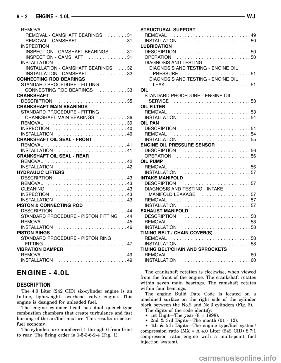
REMOVAL - CAMSHAFT BEARINGS.......31
REMOVAL - CAMSHAFT................31
INSPECTION
INSPECTION - CAMSHAFT BEARINGS.....31
INSPECTION - CAMSHAFT..............31
INSTALLATION
INSTALLATION - CAMSHAFT BEARINGS . . . 32
INSTALLATION - CAMSHAFT............32
CONNECTING ROD BEARINGS
STANDARD PROCEDURE - FITTING
CONNECTING ROD BEARINGS..........33
CRANKSHAFT
DESCRIPTION.........................35
CRANKSHAFT MAIN BEARINGS
STANDARD PROCEDURE - FITTING
CRANKSHAFT MAIN BEARINGS..........36
REMOVAL.............................39
INSPECTION..........................40
INSTALLATION.........................40
CRANKSHAFT OIL SEAL - FRONT
REMOVAL.............................41
INSTALLATION.........................41
CRANKSHAFT OIL SEAL - REAR
REMOVAL.............................42
INSTALLATION.........................42
HYDRAULIC LIFTERS
DESCRIPTION.........................43
REMOVAL.............................43
CLEANING............................43
INSPECTION..........................43
INSTALLATION.........................43
PISTON & CONNECTING ROD
DESCRIPTION.........................44
STANDARD PROCEDURE - PISTON FITTING . 44
REMOVAL.............................45
INSTALLATION.........................46
PISTON RINGS
STANDARD PROCEDURE - PISTON RING
FITTING.............................47
VIBRATION DAMPER
REMOVAL.............................49
INSTALLATION.........................49STRUCTURAL SUPPORT
REMOVAL.............................49
INSTALLATION.........................50
LUBRICATION
DESCRIPTION.........................50
OPERATION...........................50
DIAGNOSIS AND TESTING
DIAGNOSIS AND TESTING - ENGINE OIL
PRESSURE..........................51
DIAGNOSIS AND TESTING - ENGINE OIL
LEAK...............................51
OIL
STANDARD PROCEDURE - ENGINE OIL
SERVICE............................53
OIL FILTER
REMOVAL.............................53
INSTALLATION.........................54
OIL PAN
DESCRIPTION.........................54
REMOVAL.............................54
INSTALLATION.........................55
ENGINE OIL PRESSURE SENSOR
DESCRIPTION.........................56
OPERATION...........................56
OIL PUMP
REMOVAL.............................56
INSTALLATION.........................57
INTAKE MANIFOLD
DESCRIPTION.........................57
DIAGNOSIS AND TESTING - INTAKE
MANIFOLD LEAKAGE..................57
REMOVAL.............................57
INSTALLATION.........................57
EXHAUST MANIFOLD
DESCRIPTION.........................58
REMOVAL.............................58
INSTALLATION.........................58
TIMING BELT / CHAIN COVER(S)
REMOVAL.............................58
INSTALLATION.........................58
TIMING BELT/CHAIN AND SPROCKETS
REMOVAL.............................60
INSTALLATION.........................60
ENGINE - 4.0L
DESCRIPTION
The 4.0 Liter (242 CID) six-cylinder engine is an
In-line, lightweight, overhead valve engine. This
engine is designed for unleaded fuel.
The engine cylinder head has dual quench-type
combustion chambers that create turbulence and fast
burning of the air/fuel mixture. This results in better
fuel economy.
The cylinders are numbered 1 through 6 from front
to rear. The firing order is 1-5-3-6-2-4 (Fig. 1).The crankshaft rotation is clockwise, when viewed
from the front of the engine. The crankshaft rotates
within seven main bearings. The camshaft rotates
within four bearings.
The engine Build Date Code is located on a
machined surface on the right side of the cylinder
block between the No.2 and No.3 cylinders (Fig. 2).
The digits of the code identify:
²1st DigitÐThe year (8 = 1998).
²2nd & 3rd DigitsÐThe month (01 - 12).
²4th & 5th DigitsÐThe engine type/fuel system/
compression ratio (MX = A 4.0 Liter (242 CID) 8.7:1
compression ratio engine with a multi-point fuel
injection system).
9 - 2 ENGINE - 4.0LWJ
Page 1248 of 2199
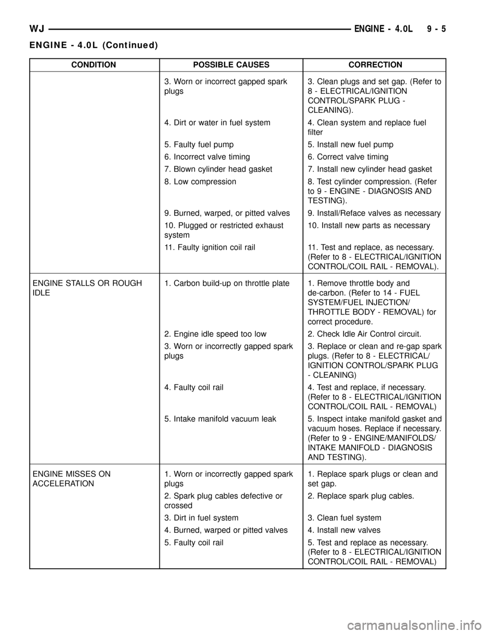
CONDITION POSSIBLE CAUSES CORRECTION
3. Worn or incorrect gapped spark
plugs3. Clean plugs and set gap. (Refer to
8 - ELECTRICAL/IGNITION
CONTROL/SPARK PLUG -
CLEANING).
4. Dirt or water in fuel system 4. Clean system and replace fuel
filter
5. Faulty fuel pump 5. Install new fuel pump
6. Incorrect valve timing 6. Correct valve timing
7. Blown cylinder head gasket 7. Install new cylinder head gasket
8. Low compression 8. Test cylinder compression. (Refer
to 9 - ENGINE - DIAGNOSIS AND
TESTING).
9. Burned, warped, or pitted valves 9. Install/Reface valves as necessary
10. Plugged or restricted exhaust
system10. Install new parts as necessary
11. Faulty ignition coil rail 11. Test and replace, as necessary.
(Refer to 8 - ELECTRICAL/IGNITION
CONTROL/COIL RAIL - REMOVAL).
ENGINE STALLS OR ROUGH
IDLE1. Carbon build-up on throttle plate 1. Remove throttle body and
de-carbon. (Refer to 14 - FUEL
SYSTEM/FUEL INJECTION/
THROTTLE BODY - REMOVAL) for
correct procedure.
2. Engine idle speed too low 2. Check Idle Air Control circuit.
3. Worn or incorrectly gapped spark
plugs3. Replace or clean and re-gap spark
plugs. (Refer to 8 - ELECTRICAL/
IGNITION CONTROL/SPARK PLUG
- CLEANING)
4. Faulty coil rail 4. Test and replace, if necessary.
(Refer to 8 - ELECTRICAL/IGNITION
CONTROL/COIL RAIL - REMOVAL)
5. Intake manifold vacuum leak 5. Inspect intake manifold gasket and
vacuum hoses. Replace if necessary.
(Refer to 9 - ENGINE/MANIFOLDS/
INTAKE MANIFOLD - DIAGNOSIS
AND TESTING).
ENGINE MISSES ON
ACCELERATION1. Worn or incorrectly gapped spark
plugs1. Replace spark plugs or clean and
set gap.
2. Spark plug cables defective or
crossed2. Replace spark plug cables.
3. Dirt in fuel system 3. Clean fuel system
4. Burned, warped or pitted valves 4. Install new valves
5. Faulty coil rail 5. Test and replace as necessary.
(Refer to 8 - ELECTRICAL/IGNITION
CONTROL/COIL RAIL - REMOVAL)
WJENGINE - 4.0L 9 - 5
ENGINE - 4.0L (Continued)
Page 1250 of 2199
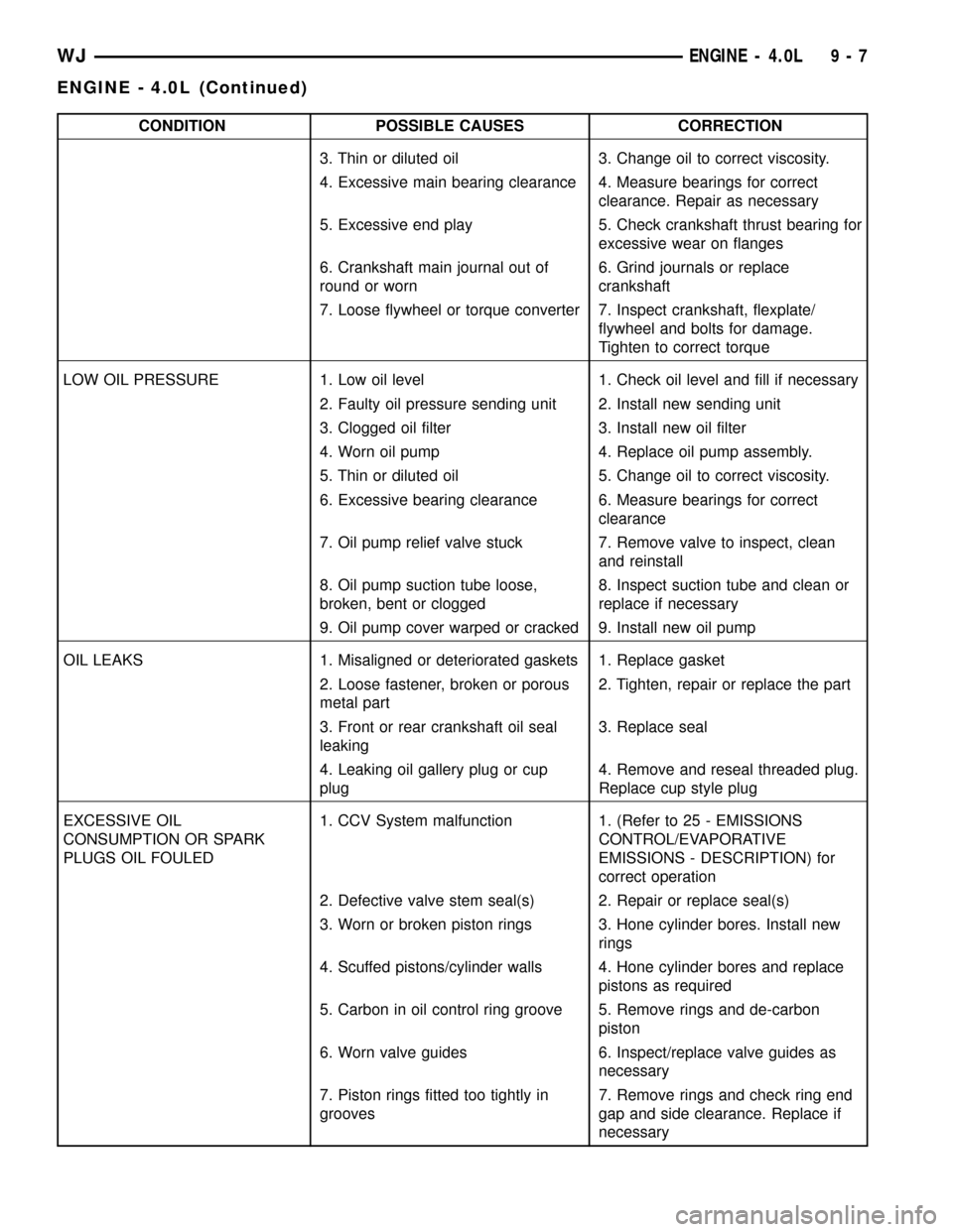
CONDITION POSSIBLE CAUSES CORRECTION
3. Thin or diluted oil 3. Change oil to correct viscosity.
4. Excessive main bearing clearance 4. Measure bearings for correct
clearance. Repair as necessary
5. Excessive end play 5. Check crankshaft thrust bearing for
excessive wear on flanges
6. Crankshaft main journal out of
round or worn6. Grind journals or replace
crankshaft
7. Loose flywheel or torque converter 7. Inspect crankshaft, flexplate/
flywheel and bolts for damage.
Tighten to correct torque
LOW OIL PRESSURE 1. Low oil level 1. Check oil level and fill if necessary
2. Faulty oil pressure sending unit 2. Install new sending unit
3. Clogged oil filter 3. Install new oil filter
4. Worn oil pump 4. Replace oil pump assembly.
5. Thin or diluted oil 5. Change oil to correct viscosity.
6. Excessive bearing clearance 6. Measure bearings for correct
clearance
7. Oil pump relief valve stuck 7. Remove valve to inspect, clean
and reinstall
8. Oil pump suction tube loose,
broken, bent or clogged8. Inspect suction tube and clean or
replace if necessary
9. Oil pump cover warped or cracked 9. Install new oil pump
OIL LEAKS 1. Misaligned or deteriorated gaskets 1. Replace gasket
2. Loose fastener, broken or porous
metal part2. Tighten, repair or replace the part
3. Front or rear crankshaft oil seal
leaking3. Replace seal
4. Leaking oil gallery plug or cup
plug4. Remove and reseal threaded plug.
Replace cup style plug
EXCESSIVE OIL
CONSUMPTION OR SPARK
PLUGS OIL FOULED1. CCV System malfunction 1. (Refer to 25 - EMISSIONS
CONTROL/EVAPORATIVE
EMISSIONS - DESCRIPTION) for
correct operation
2. Defective valve stem seal(s) 2. Repair or replace seal(s)
3. Worn or broken piston rings 3. Hone cylinder bores. Install new
rings
4. Scuffed pistons/cylinder walls 4. Hone cylinder bores and replace
pistons as required
5. Carbon in oil control ring groove 5. Remove rings and de-carbon
piston
6. Worn valve guides 6. Inspect/replace valve guides as
necessary
7. Piston rings fitted too tightly in
grooves7. Remove rings and check ring end
gap and side clearance. Replace if
necessary
WJENGINE - 4.0L 9 - 7
ENGINE - 4.0L (Continued)
Page 1252 of 2199
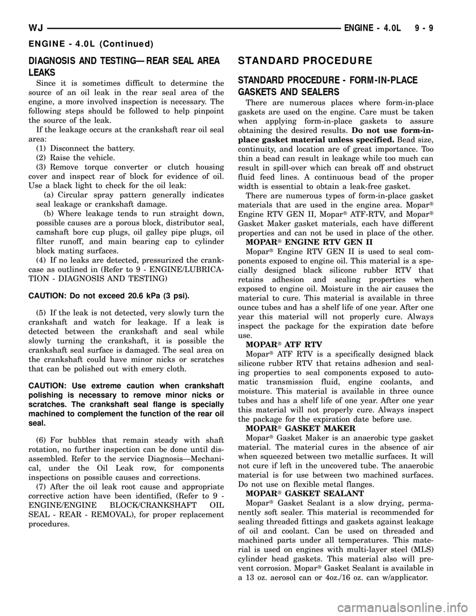
DIAGNOSIS AND TESTINGÐREAR SEAL AREA
LEAKS
Since it is sometimes difficult to determine the
source of an oil leak in the rear seal area of the
engine, a more involved inspection is necessary. The
following steps should be followed to help pinpoint
the source of the leak.
If the leakage occurs at the crankshaft rear oil seal
area:
(1) Disconnect the battery.
(2) Raise the vehicle.
(3) Remove torque converter or clutch housing
cover and inspect rear of block for evidence of oil.
Use a black light to check for the oil leak:
(a) Circular spray pattern generally indicates
seal leakage or crankshaft damage.
(b) Where leakage tends to run straight down,
possible causes are a porous block, distributor seal,
camshaft bore cup plugs, oil galley pipe plugs, oil
filter runoff, and main bearing cap to cylinder
block mating surfaces.
(4) If no leaks are detected, pressurized the crank-
case as outlined in (Refer to 9 - ENGINE/LUBRICA-
TION - DIAGNOSIS AND TESTING)
CAUTION: Do not exceed 20.6 kPa (3 psi).
(5) If the leak is not detected, very slowly turn the
crankshaft and watch for leakage. If a leak is
detected between the crankshaft and seal while
slowly turning the crankshaft, it is possible the
crankshaft seal surface is damaged. The seal area on
the crankshaft could have minor nicks or scratches
that can be polished out with emery cloth.
CAUTION: Use extreme caution when crankshaft
polishing is necessary to remove minor nicks or
scratches. The crankshaft seal flange is specially
machined to complement the function of the rear oil
seal.
(6) For bubbles that remain steady with shaft
rotation, no further inspection can be done until dis-
assembled. Refer to the service DiagnosisÐMechani-
cal, under the Oil Leak row, for components
inspections on possible causes and corrections.
(7) After the oil leak root cause and appropriate
corrective action have been identified, (Refer to 9 -
ENGINE/ENGINE BLOCK/CRANKSHAFT OIL
SEAL - REAR - REMOVAL), for proper replacement
procedures.
STANDARD PROCEDURE
STANDARD PROCEDURE - FORM-IN-PLACE
GASKETS AND SEALERS
There are numerous places where form-in-place
gaskets are used on the engine. Care must be taken
when applying form-in-place gaskets to assure
obtaining the desired results.Do not use form-in-
place gasket material unless specified.Bead size,
continuity, and location are of great importance. Too
thin a bead can result in leakage while too much can
result in spill-over which can break off and obstruct
fluid feed lines. A continuous bead of the proper
width is essential to obtain a leak-free gasket.
There are numerous types of form-in-place gasket
materials that are used in the engine area. Mopart
Engine RTV GEN II, MopartATF-RTV, and Mopart
Gasket Maker gasket materials, each have different
properties and can not be used in place of the other.
MOPARtENGINE RTV GEN II
MopartEngine RTV GEN II is used to seal com-
ponents exposed to engine oil. This material is a spe-
cially designed black silicone rubber RTV that
retains adhesion and sealing properties when
exposed to engine oil. Moisture in the air causes the
material to cure. This material is available in three
ounce tubes and has a shelf life of one year. After one
year this material will not properly cure. Always
inspect the package for the expiration date before
use.
MOPARtATF RTV
MopartATF RTV is a specifically designed black
silicone rubber RTV that retains adhesion and seal-
ing properties to seal components exposed to auto-
matic transmission fluid, engine coolants, and
moisture. This material is available in three ounce
tubes and has a shelf life of one year. After one year
this material will not properly cure. Always inspect
the package for the expiration date before use.
MOPARtGASKET MAKER
MopartGasket Maker is an anaerobic type gasket
material. The material cures in the absence of air
when squeezed between two metallic surfaces. It will
not cure if left in the uncovered tube. The anaerobic
material is for use between two machined surfaces.
Do not use on flexible metal flanges.
MOPARtGASKET SEALANT
MopartGasket Sealant is a slow drying, perma-
nently soft sealer. This material is recommended for
sealing threaded fittings and gaskets against leakage
of oil and coolant. Can be used on threaded and
machined parts under all temperatures. This mate-
rial is used on engines with multi-layer steel (MLS)
cylinder head gaskets. This material also will pre-
vent corrosion. MopartGasket Sealant is available in
a 13 oz. aerosol can or 4oz./16 oz. can w/applicator.
WJENGINE - 4.0L 9 - 9
ENGINE - 4.0L (Continued)
Page 1253 of 2199
FORM-IN-PLACE GASKET AND SEALER
APPLICATION
Assembling parts using a form-in-place gasket
requires care but it's easier then using precut gaskets.
MopartGasket Maker material should be applied
sparingly 1 mm (0.040 in.) diameter or less of sealant
to one gasket surface. Be certain the material sur-
rounds each mounting hole. Excess material can eas-
ily be wiped off. Components should be torqued in
place within 15 minutes. The use of a locating dowel
is recommended during assembly to prevent smear-
ing material off the location.
MopartEngine RTV GEN II or ATF RTV gasket
material should be applied in a continuous bead
approximately 3 mm (0.120 in.) in diameter. All
mounting holes must be circled. For corner sealing, a
3.17 or 6.35 mm (1/8 or 1/4 in.) drop is placed in the
center of the gasket contact area. Uncured sealant
may be removed with a shop towel. Components
should be torqued in place while the sealant is still
wet to the touch (within 10 minutes). The usage of a
locating dowel is recommended during assembly to
prevent smearing material off the location.
MopartGasket Sealant in an aerosol can should be
applied using a thin, even coat sprayed completely
over both surfaces to be joined, and both sides of a
gasket. Then proceed with assembly. Material in a
can w/applicator can be brushed on evenly over the
sealing surfaces. Material in an aerosol can should be
used on engines with multi-layer steel gaskets.
STANDARD PROCEDURE - REPAIR DAMAGED
OR WORN THREADS
CAUTION: Be sure that the tapped holes maintain
the original center line.
Damaged or worn threads can be repaired. Essen-
tially, this repair consists of:
²Drilling out worn or damaged threads.
²Tapping the hole with a special Heli-Coil Tap, or
equivalent.
²Installing an insert into the tapped hole to bring
the hole back to its original thread size.
STANDARD PROCEDUREÐHYDROSTATIC LOCK
CAUTION: DO NOT use the starter motor to rotate
the crankshaft. Severe damage could occur.
When an engine is suspected of hydrostatic lock
(regardless of what caused the problem), follow the
steps below.
(1) Perform the Fuel Pressure Release Procedure
(Refer to 14 - FUEL SYSTEM/FUEL DELIVERY -
STANDARD PROCEDURE).(2) Disconnect the negative cable(s) from the bat-
tery.
(3) Inspect air cleaner, induction system, and
intake manifold to ensure system is dry and clear of
foreign material.
(4) Place a shop towel around the spark plugs to
catch any fluid that may possibly be under pressure
in the cylinder head. Remove the spark plugs.
(5) With all spark plugs removed, rotate the crank-
shaft using a breaker bar and socket.
(6) Identify the fluid in the cylinders (coolant, fuel,
oil, etc.).
(7) Be sure all fluid has been removed from the
cylinders.
(8) Repair engine or components as necessary to
prevent this problem from occurring again.
(9) Squirt a small amount of engine oil into the
cylinders to lubricate the walls. This will prevent
damage on restart.
(10) Install new spark plugs. Tighten the spark
plugs to 41 N´m (30 ft. lbs.) torque.
(11) Drain engine oil. Remove and discard the oil
filter.
(12) Install the drain plug. Tighten the plug to 34
N´m (25 ft. lbs.) torque.
(13) Install a new oil filter.
(14) Fill engine crankcase with the specified
amount and grade of oil. (Refer to LUBRICATION &
MAINTENANCE - SPECIFICATIONS).
(15) Connect the negative cable(s) to the battery.
(16) Start the engine and check for any leaks.
STANDARD PROCEDURE - CYLINDER BORE
HONING
Before honing, stuff plenty of clean shop towels
under the bores and over the crankshaft to keep
abrasive materials from entering the crankshaft
area.
(1)
Used carefully, the Cylinder Bore Sizing Hone
C-823, equipped with 220 grit stones, is the best tool
for this job. In addition to deglazing, it will reduce
taper and out-of-round, as well as removing light scuff-
ing, scoring and scratches. Usually, a few strokes will
clean up a bore and maintain the required limits.
CAUTION: DO NOT use rigid type hones to remove
cylinder wall glaze.
(2) Deglazing of the cylinder walls may be done if
the cylinder bore is straight and round. Use a cylin-
der surfacing hone, Honing Tool C-3501, equipped
with 280 grit stones (C-3501-3810). about 20-60
strokes, depending on the bore condition, will be suf-
ficient to provide a satisfactory surface. Using honing
oil C-3501-3880, or a light honing oil, available from
major oil distributors.
9 - 10 ENGINE - 4.0LWJ
ENGINE - 4.0L (Continued)
Page 1261 of 2199
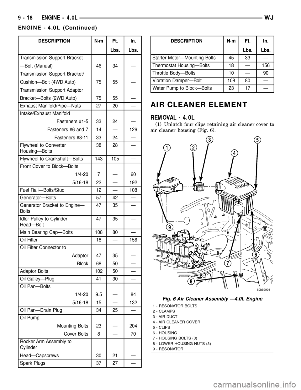
DESCRIPTION N´m Ft. In.
Lbs. Lbs.
Transmission Support Bracket
ÐBolt (Manual) 46 34 Ð
Transmission Support Bracket/
CushionÐBolt (4WD Auto) 75 55 Ð
Transmission Support Adaptor
BracketÐBolts (2WD Auto) 75 55 Ð
Exhaust Manifold/PipeÐNuts 27 20 Ð
Intake/Exhaust Manifold
Fasteners #1-5 33 24 Ð
Fasteners #6 and 7 14 Ð 126
Fasteners #8-11 33 24 Ð
Flywheel to Converter
HousingÐBolts38 28 Ð
Flywheel to CrankshaftÐBolts 143 105 Ð
Front Cover to BlockÐBolts
1/4-20 7 Ð 60
5/16-18 22 Ð 192
Fuel RailÐBolts/Stud 12 Ð 108
GeneratorÐBolts 57 42 Ð
Generator Bracket to EngineÐ
Bolts47 35 Ð
Idler Pulley to Cylinder
HeadÐBolt47 35 Ð
Main Bearing CapÐBolts 108 80 Ð
Oil Filter 18 Ð 156
Oil Filter Connector to
Adaptor 47 35 Ð
Block 68 50 Ð
Adaptor Bolts 102 50 Ð
Oil GalleyÐPlug 41 30 Ð
Oil PanÐBolts
1/4-20 9.5 Ð 84
5/16-18 15 Ð 132
Oil PanÐDrain Plug 34 25 Ð
Oil Pump
Mounting Bolts 23 Ð 204
Cover Bolts 8 Ð 70
Rocker Arm Assembly to
Cylinder
HeadÐCapscrews 30 21 Ð
Spark Plugs 37 27 ÐDESCRIPTION N´m Ft. In.
Lbs. Lbs.
Starter MotorÐMounting Bolts 45 33 Ð
Thermostat HousingÐBolts 18 Ð 156
Throttle BodyÐBolts 10 Ð 90
Vibration DamperÐBolt 108 80 Ð
Water Pump to BlockÐBolts 23 17 Ð
AIR CLEANER ELEMENT
REMOVAL - 4.0L
(1) Unlatch four clips retaining air cleaner cover to
air cleaner housing (Fig. 6).
Fig. 6 Air Cleaner Assembly Ð4.0L Engine
1 - RESONATOR BOLTS
2 - CLAMPS
3 - AIR DUCT
4 - AIR CLEANER COVER
5 - CLIPS
6 - HOUSING
7 - HOUSING BOLTS (3)
8 - LOWER HOUSING NUTS (3)
9 - RESONATOR
9 - 18 ENGINE - 4.0LWJ
ENGINE - 4.0L (Continued)