2002 JEEP GRAND CHEROKEE blower
[x] Cancel search: blowerPage 1145 of 2199
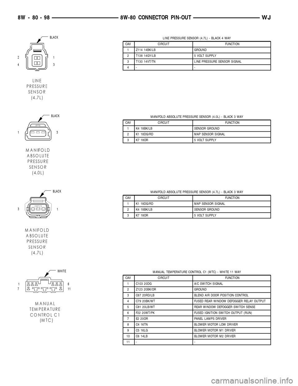
LINE PRESSURE SENSOR (4.7L) - BLACK 4 WAY
CAV CIRCUIT FUNCTION
1 Z114 14BK/LB GROUND
2 T138 14GY/LB 5 VOLT SUPPLY
3 T130 14VT/TN LINE PRESSURE SENSOR SIGNAL
4- -
MANIFOLD ABSOLUTE PRESSURE SENSOR (4.0L) - BLACK 3 WAY
CAV CIRCUIT FUNCTION
1 K4 18BK/LB SENSOR GROUND
2 K1 18DG/RD MAP SENSOR SIGNAL
3 K7 18OR 5 VOLT SUPPLY
MANIFOLD ABSOLUTE PRESSURE SENSOR (4.7L) - BLACK 3 WAY
CAV CIRCUIT FUNCTION
1 K1 18DG/RD MAP SENSOR SIGNAL
2 K4 18BK/LB SENSOR GROUND
3 K7 18OR 5 VOLT SUPPLY
MANUAL TEMPERATURE CONTROL C1 (MTC) - WHITE 11 WAY
CAV CIRCUIT FUNCTION
1 C103 20DG A/C SWITCH SIGNAL
2 Z123 20BK/OR GROUND
3 C67 20RD/LB BLEND AIR DOOR POSITION CONTROL
4 C79 20BK/WT FUSED REAR WINDOW DEFOGGER RELAY OUTPUT
5 C81 20LB/WT REAR WINDOW DEFOGGER SWITCH SENSE
6 F22 20WT/PK FUSED IGNITION SWITCH OUTPUT (RUN)
7 E2 20OR PANEL LAMPS DRIVER
8 C4 16TN BLOWER MOTOR LOW DRIVER
9 C5 16LG BLOWER MOTOR M1 DRIVER
10 C6 14LB BLOWER MOTOR M2 DRIVER
11 - -
8W - 80 - 98 8W-80 CONNECTOR PIN-OUTWJ
Page 1146 of 2199
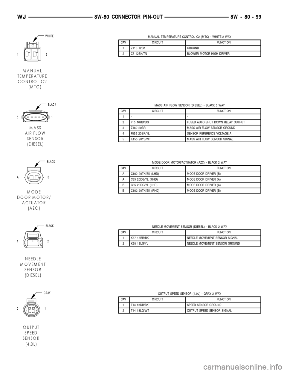
MANUAL TEMPERATURE CONTROL C2 (MTC) - WHITE 2 WAY
CAV CIRCUIT FUNCTION
1 Z118 12BK GROUND
2 C7 12BK/TN BLOWER MOTOR HIGH DRIVER
MASS AIR FLOW SENSOR (DIESEL) - BLACK 5 WAY
CAV CIRCUIT FUNCTION
1- -
2 F15 16RD/DG FUSED AUTO SHUT DOWN RELAY OUTPUT
3 Z189 20BR MASS AIR FLOW SENSOR GROUND
4 F855 20BR/YL SENSOR REFERENCE VOLTAGE A
5 K155 20YL/WT MASS AIR FLOW SENSOR SIGNAL
MODE DOOR MOTOR/ACTUATOR (AZC) - BLACK 2 WAY
CAV CIRCUIT FUNCTION
A C102 20TN/BK (LHD) MODE DOOR DRIVER (B)
A C35 20DG/YL (RHD) MODE DOOR DRIVER (A)
B C35 20DG/YL (LHD) MODE DOOR DRIVER (A)
B C102 20TN/BK (RHD) MODE DOOR DRIVER (B)
NEEDLE MOVEMENT SENSOR (DIESEL) - BLACK 2 WAY
CAV CIRCUIT FUNCTION
1 K67 18BR/BK NEEDLE MOVEMENT SENSOR SIGNAL
2 K68 18LG/YL NEEDLE MOVEMENT SENSOR GROUND
OUTPUT SPEED SENSOR (4.0L) - GRAY 2 WAY
CAV CIRCUIT FUNCTION
1 T13 18DB/BK SPEED SENSOR GROUND
2 T14 18LG/WT OUTPUT SPEED SENSOR SIGNAL
WJ8W-80 CONNECTOR PIN-OUT 8W - 80 - 99
Page 1176 of 2199
8W-91 CONNECTOR/GROUND/SPLICE LOCATION
TABLE OF CONTENTS
page
CONNECTOR/GROUND/SPLICE LOCATION
DESCRIPTION..........................1
CONNECTOR/GROUND/SPLICE
LOCATION
DESCRIPTION
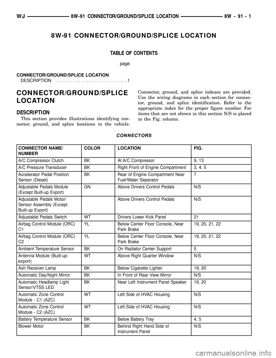
This section provides illustrations identifying con-
nector, ground, and splice locations in the vehicle.Connector, ground, and splice indexes are provided.
Use the wiring diagrams in each section for connec-
tor, ground, and splice identification. Refer to the
appropriate index for the proper figure number. For
items that are not shown in this section N/S is placed
in the Fig. column.
CONNECTORS
CONNECTOR NAME/
NUMBERCOLOR LOCATION FIG.
A/C Compressor Clutch BK At A/C Compressor 9, 13
A/C Pressure Transducer BK Right Front of Engine Compartment 3, 4, 5
Accelerator Pedal Position
Sensor (Diesel)BK Rear of Engine Compartment Near
Fuel/Water Seperator7
Adjustable Pedals Module
(Except Built-up Export)GN Above Drivers Control Pedals N/S
Adjustable Pedals Motor/
Sensor Assembly (Except
Built-up Export)Above Drivers Control Pedals N/S
Adjustable Pedals Switch WT Drivers Lower Kick Panel 21
Airbag Control Module (ORC)
C1YL Below Center Floor Console, Near
Park Brake19, 20, 21, 22
Airbag Control Module (ORC)
C2YL Below Center Floor Console, Near
Park Brake19, 20, 21, 22
Ambient Temperature Sensor BK On Radiator Center Support 5
Antenna Module (Built-up-
export)WT Above Right Quarter Window N/S
Ash Receiver Lamp BK Below Cigarette Lighter 19, 20
Automatic Day/Night Mirror BK In Front of Rear View Mirror N/S
Automatic Headlamp Light
Sensor/VTSS LEDBK Near Left Instrument Panel Speaker 19, 20
Automatic Zone Control
Module - C1 (AZC)WT Left Side of HVAC Housing N/S
Automatic Zone Control
Module - C2 (AZC)WT Left Side of HVAC Housing N/S
Battery Temperature Sensor BK Below Battery Tray 4, 5
Blower Motor BK Behind Right Hand Side of
Instrument PanelN/S
WJ8W-91 CONNECTOR/GROUND/SPLICE LOCATION 8W - 91 - 1
Page 1177 of 2199
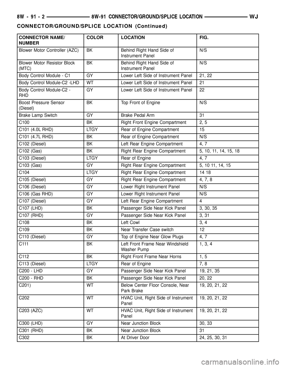
CONNECTOR NAME/
NUMBERCOLOR LOCATION FIG.
Blower Motor Controller (AZC) BK Behind Right Hand Side of
Instrument PanelN/S
Blower Motor Resistor Block
(MTC)BK Behind Right Hand Side of
Instrument PanelN/S
Body Control Module - C1 GY Lower Left Side of Instrument Panel 21, 22
Body Control Module-C2 -LHD WT Lower Left Side of Instrument Panel 21
Body Control Module-C2 -
RHDGY Lower Left Side of Instrument Panel 22
Boost Pressure Sensor
(Diesel)BK Top Front of Engine N/S
Brake Lamp Switch GY Brake Pedal Arm 31
C100 BK Right Front Engine Compartment 2, 5
C101 (4.0L RHD) LTGY Rear of Engine Compartment 15
C101 (4.7L RHD) BK Rear of Engine Compartment N/S
C102 (Diesel) BK Left Rear Engine Compartment 4, 7
C102 (Gas) BK Right Rear Engine Compartment 5, 10, 11, 14, 15, 18
C103 (Diesel) LTGY Rear of Engine 4, 7
C103 (Gas) GY Right Rear Engine Compartment 5, 10 11, 14, 15
C104 LTGY Right Rear Engine Compartment 14 18
C105 (Diesel) GY Right Rear Engine Compartment 4, 7, 8
C106 (Diesel) GY Lower Right Instrument Panel N/S
C106 (Gas RHD) GY Lower Right Instrument Panel N/S
C107 (Diesel) GY Left Rear Engine Compartment 4
C107 (LHD) BK Passenger Side Near Kick Panel 3, 30, 35
C107 (RHD) GY Passenger Side Near Kick Panel 3, 31
C108 BK Left Cowl 3, 4
C109 BK Near Transfer Case switch 12
C110 (Diesel) GY Top of Engine Near Glow Plugs 4, 7
C111 BK Left Front Frame Near Windshield
Washer Pump1, 3, 4
C112 BK Right Front Frame Near Horns 1, 5
C113 (Diesel) LTGY Rear of Engine 7, 8
C200 - LHD GY Passenger Side Near Kick Panel 19, 21, 35
C200 - RHD BK Passenger Side Near Kick Panel 20, 22
C201) WT Below Center Floor Console, Near
Park Brake19, 20, 21, 22
C202 WT HVAC Unit, Right Side of Instrument
Panel19, 20, 21, 22
C203 (AZC) WT HVAC Unit, Right Side of Instrument
Panel19, 20, 21, 22
C300 (LHD) GY Near Junction Block 30, 33
C301 (RHD) BK Near Junction Block 31
C302 BK At Driver Door 24, 25, 30, 31
8W - 91 - 2 8W-91 CONNECTOR/GROUND/SPLICE LOCATIONWJ
CONNECTOR/GROUND/SPLICE LOCATION (Continued)
Page 1875 of 2199

leak area. If the hose cannot be positioned without
being held, have someone help do the water test.
Some water leaks must be tested for a considerable
length of time to become apparent. When a leak
appears, find the highest point of the water track or
drop. The highest point usually will show the point of
entry. After leak point has been found, repair the
leak and water test to verify that the leak has
stopped.
Locating the entry point of water that is leaking
into a cavity between panels can be difficult. The
trapped water may splash or run from the cavity,
often at a distance from the entry point. Most water
leaks of this type become apparent after accelerating,
stopping, turning, or when on an incline.
MIRROR INSPECTION METHOD
When a leak point area is visually obstructed, use
a suitable mirror to gain visual access. A mirror can
also be used to deflect light to a limited-access area
to assist in locating a leak point.
BRIGHT LIGHT LEAK TEST METHOD
Some water leaks in the luggage compartment can
be detected without water testing. Position the vehi-
cle in a brightly lit area. From inside the darkened
luggage compartment inspect around seals and body
seams. If necessary, have a helper direct a drop light
over the suspected leak areas around the luggage
compartment. If light is visible through a normally
sealed location, water could enter through the open-
ing.
PRESSURIZED LEAK TEST METHOD
When a water leak into the passenger compart-
ment cannot be detected by water testing, pressurize
the passenger compartment and soap test exterior of
the vehicle. To pressurize the passenger compart-
ment, close all doors and windows, start engine, and
set heater control to high blower in HEAT position. If
engine can not be started, connect a charger to the
battery to ensure adequate voltage to the blower.
With interior pressurized, apply dish detergent solu-
tion to suspected leak area on the exterior of the
vehicle. Apply detergent solution with spray device or
soft bristle brush. If soap bubbles occur at a body
seam, joint, seal or gasket, the leak entry point could
be at that location.
WIND NOISE
Wind noise is the result of most air leaks. Air leaks
can be caused by poor sealing, improper body compo-
nent alignment, body seam porosity, or missing plugs
in the engine compartment or door hinge pillar areas.
All body sealing points should be airtight in normal
driving conditions. Moving sealing surfaces will notalways seal airtight under all conditions. At times,
side glass or door seals will allow wind noise to be
noticed in the passenger compartment during high
cross winds. Over compensating on door or glass
adjustments to stop wind noise that occurs under
severe conditions can cause premature seal wear and
excessive closing or latching effort. After a repair pro-
cedure has been performed, test vehicle to verify
noise has stopped before returning vehicle to use.
Wind noise can also be caused by improperly fitted
exterior moldings or body ornamentation. Loose
moldings can flutter, creating a buzzing or chattering
noise. An open cavity or protruding edge can create a
whistling or howling noise. Inspect the exterior of the
vehicle to verify that these conditions do not exist.
VISUAL INSPECTION BEFORE TESTS
Verify that floor and body plugs are in place and
body components are aligned and sealed. If compo-
nent alignment or sealing is necessary, refer to the
appropriate section of this group for proper proce-
dures.
ROAD TESTING WIND NOISE
(1) Drive the vehicle to verify the general location
of the wind noise.
(2) Apply 50 mm (2 in.) masking tape in 150 mm
(6 in.) lengths along weatherstrips, weld seams or
moldings. After each length is applied, drive the vehi-
cle. If noise goes away after a piece of tape is applied,
remove tape, locate, and repair defect.
POSSIBLE CAUSE OF WIND NOISE
²Moldings standing away from body surface can
catch wind and whistle.
²Gaps in sealed areas behind overhanging body
flanges can cause wind-rushing sounds.
²Misaligned movable components.
²Missing or improperly installed plugs in pillars.
²Weld burn through holes.
STANDARD PROCEDURE
STANDARD PROCEDURE - BODY LUBRICATION
All mechanisms and linkages should be lubricated
when necessary. This will maintain ease of operation
and provide protection against rust and excessive
wear. The weatherstrip seals should be lubricated to
prolong their life as well as to improve door sealing.
All applicable exterior and interior vehicle operat-
ing mechanisms should be inspected and cleaned.
Pivot/sliding contact areas on the mechanisms should
then be lubricated.
(1) When necessary, lubricate the operating mech-
anisms with the specified lubricants.
23 - 2 BODYWJ
BODY (Continued)
Page 1915 of 2199

(35) Disconnect the two instrument panel wire
harness connectors from the two heater and air con-
ditioner housing connectors located near the blower
motor on the passenger side end of the housing (Fig.
12).
(36) Remove the two screws that secure the pas-
senger side instrument panel structural duct to the
heater and air conditioner housing (Fig. 13).(37) Remove the two screws that secure the instru-
ment panel to the passenger side cowl side inner
panel (Fig. 14).
(38) With the aid of an assistant, lift the instru-
ment panel assembly upward off of the studs on the
dash panel near the windshield fence line and to dis-
engage the molded plastic hook formations on the
instrument panel structural duct from the guide
holes at each cowl side inner panel.
(39)
Pull the instrument panel rearward from the
dash panel and the cowl side inner panels and remove it
through the driver side front door of the vehicle.
Fig. 12 Heater and Air Conditioner Housing
Connections
1 - INSTRUMENT PANEL
2 - HVAC HOUSING
3 - INSTRUMENT PANEL WIRE HARNESS
4 - BLOWER MOTOR
Fig. 13 Passenger Side Instrument Panel to
Heater-A/C Housing Mounting
1 - HEATER AND AIR CONDITIONER HOUSING
2 - INSTRUMENT PANEL STRUCTURAL DUCT
3 - SCREW (2)
Fig. 14 Instrument Panel to Passenger Side Cowl
Side Inner Panel Mounting
1 - COWL SIDE INNER PANEL
2 - INSTRUMENT PANEL STRUCTURAL DUCT
3 - SCREW (2)
23 - 42 INSTRUMENT PANEL SYSTEMWJ
INSTRUMENT PANEL SYSTEM (Continued)
Page 1916 of 2199

INSTALLATION
WARNING: ON VEHICLES EQUIPPED WITH AIR-
BAGS, DISABLE THE AIRBAG SYSTEM BEFORE
ATTEMPTING ANY STEERING WHEEL, STEERING
COLUMN, OR INSTRUMENT PANEL COMPONENT
DIAGNOSIS OR SERVICE. DISCONNECT AND ISO-
LATE THE BATTERY NEGATIVE (GROUND) CABLE,
THEN WAIT TWO MINUTES FOR THE AIRBAG SYS-
TEM CAPACITOR TO DISCHARGE BEFORE PER-
FORMING FURTHER DIAGNOSIS OR SERVICE. THIS
IS THE ONLY SURE WAY TO DISABLE THE AIRBAG
SYSTEM. FAILURE TO TAKE THE PROPER PRE-
CAUTIONS COULD RESULT IN ACCIDENTAL AIR-
BAG DEPLOYMENT AND POSSIBLE PERSONAL
INJURY.
(1) Prior to installing the instrument panel into
the vehicle, loosen the three nuts that secure the
instrument panel intermediate bracket and the accel-
erator pedal assembly to the studs on the dash panel
(Fig. 8).
(2) With the aid of an assistant, load the instru-
ment panel assembly through the driver side front
door of the vehicle and hang it on the studs on the
dash panel near the windshield fence line (Fig. 1).
(3) Be certain that the molded plastic hook forma-
tions on the instrument panel structural duct are
inserted into and seated in the guide holes at each
cowl side inner panel.
(4) Loosely install the two screws that secure each
end of the instrument panel to the cowl side inner
panels.
(5) Install and tighten the two screws that secure
the passenger side instrument panel structural duct
to the heater and air conditioner housing (Fig. 13).
Tighten the screws to 11.8 N´m (105 in. lbs.).
(6) Install and tighten the one screw that secures
the instrument panel steering column support
bracket to the driver side end of the heater and air
conditioner housing (Fig. 7). Tighten the screw to
11.8 N´m (105 in. lbs.).
(7) Tighten the two screws that secure each end of
the instrument panel to the cowl side inner panels
(Fig. 10) and (Fig. 14). Tighten the screws to 11.8
N´m (105 in. lbs.).
(8) Install and tighten the one screw that secures
the instrument panel steering column support
bracket to the intermediate bracket on the driver
side dash panel (Fig. 8). Tighten the screw to 11.3
N´m (100 in. lbs.).
(9) Tighten the three nuts that secure the instru-
ment panel intermediate bracket and the accelerator
pedal assembly to the studs on the dash panel.
Tighten the nuts to 11.3 N´m (100 in. lbs.).(10) Install and tighten the four nuts that secure
the instrument panel to the studs on the dash panel
near the windshield fence line. Tighten the nuts to
11.8 N´m (105 in. lbs.).
(11) Install and tighten the nut that secures the
instrument panel steering column support bracket to
the stud on the driver side cowl plenum panel (Fig.
9). Tighten the nut to 28.2 N´m (250 in. lbs.).
(12) Reinstall the instrument panel to center floor
tunnel bracket onto the instrument panel and the
floor panel transmission tunnel. (Refer to 23 - BODY/
INSTRUMENT PANEL/IP CENTER FLOOR TUN-
NEL BRACKET - INSTALLATION).
(13) Reconnect the two instrument panel wire har-
ness connectors to the two heater and air conditioner
housing connectors located near the blower motor on
the passenger side end of the housing (Fig. 12).
(14) Reconnect the two halves of the radio antenna
coaxial cable connector near the right cowl side inner
panel under the end of the instrument panel.
(15) Reconnect the instrument panel wire harness
connector to the lower cavity of the inline connector
on the passenger side cowl side inner panel and
tighten the connector screw (Fig. 11). Tighten the
screw to 4 N´m (36 in. lbs.).
(16) Reinstall the lower right center bezel onto the
instrument panel. (Refer to 23 - BODY/INSTRU-
MENT PANEL/IP LOWER RIGHT CENTER BEZEL
- INSTALLATION).
(17) Reinstall the end cap onto the instrument
panel. (Refer to 23 - BODY/INSTRUMENT PANEL/
INSTRUMENT PANEL END CAP - INSTALLA-
TION).
(18) If the vehicle is equipped with the manual
heating and air conditioning system, reconnect the
vacuum harness connector located near the driver
side of the floor panel transmission tunnel behind
the driver side floor duct.
(19) Position the driver side floor duct to the
heater and air conditioner housing near the driver
side of the floor panel transmission tunnel (Fig. 7).
(20) Install and tighten the one screw that secures
the driver side floor duct to the heater and air con-
ditioner housing near the driver side of the floor
panel transmission tunnel. Tighten the screw to 2.2
N´m (20 in. lbs.).
(21) Route the instrument panel wire harness to
the floor panel transmission tunnel and engage the
retainers that secure the harness to the mounting
brackets on the tunnel (Fig. 6).
(22) Install the instrument panel wire harness
ground eyelets to the studs on the floor panel trans-
mission tunnel in front of and behind the airbag con-
trol module and secure the eyelets with nuts. Tighten
the nuts to 7.3 N´m (65 in. lbs.).
WJINSTRUMENT PANEL SYSTEM 23 - 43
INSTRUMENT PANEL SYSTEM (Continued)
Page 1970 of 2199
releasing the control switch before the sunroof was
fully closed. The sunroof module has a water-man-
agement system. During washing high-pressure
water may be forced between the glass panel seal
and the roof opening. Normally this water will drain.
However, when some type of drying blower system is
used, like those found in automatic car washes, thewater may not have a chance to drain before the
blower forces air between the seal and the roof open-
ing. This causes the water to blow over the edge of
the module and onto the headlining.
Refer to (Fig. 1) Sunroof Assembly for exploded
view of the sunroof.
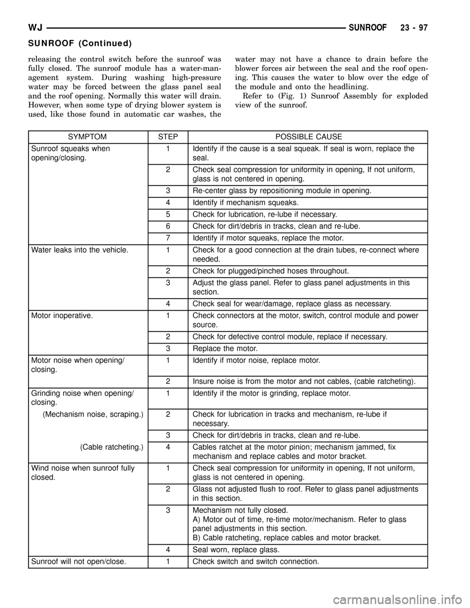
SYMPTOM STEP POSSIBLE CAUSE
Sunroof squeaks when
opening/closing.1 Identify if the cause is a seal squeak. If seal is worn, replace the
seal.
2 Check seal compression for uniformity in opening, If not uniform,
glass is not centered in opening.
3 Re-center glass by repositioning module in opening.
4 Identify if mechanism squeaks.
5 Check for lubrication, re-lube if necessary.
6 Check for dirt/debris in tracks, clean and re-lube.
7 Identify if motor squeaks, replace the motor.
Water leaks into the vehicle. 1 Check for a good connection at the drain tubes, re-connect where
needed.
2 Check for plugged/pinched hoses throughout.
3 Adjust the glass panel. Refer to glass panel adjustments in this
section.
4 Check seal for wear/damage, replace glass as necessary.
Motor inoperative. 1 Check connectors at the motor, switch, control module and power
source.
2 Check for defective control module, replace if necessary.
3 Replace the motor.
Motor noise when opening/
closing.1 Identify if motor noise, replace motor.
2 Insure noise is from the motor and not cables, (cable ratcheting).
Grinding noise when opening/
closing.1 Identify if the motor is grinding, replace motor.
(Mechanism noise, scraping.) 2 Check for lubrication in tracks and mechanism, re-lube if
necessary.
3 Check for dirt/debris in tracks, clean and re-lube.
(Cable ratcheting.) 4 Cables ratchet at the motor pinion; mechanism jammed, fix
mechanism and replace cables and motor bracket.
Wind noise when sunroof fully
closed.1 Check seal compression for uniformity in opening, If not uniform,
glass is not centered in opening.
2 Glass not adjusted flush to roof. Refer to glass panel adjustments
in this section.
3 Mechanism not fully closed.
A) Motor out of time, re-time motor/mechanism. Refer to glass
panel adjustments in this section.
B) Cable ratcheting, replace cables and motor bracket.
4 Seal worn, replace glass.
Sunroof will not open/close. 1 Check switch and switch connection.
WJSUNROOF 23 - 97
SUNROOF (Continued)