2002 JEEP GRAND CHEROKEE Lamps
[x] Cancel search: LampsPage 81 of 2199

CAUTION: Boot must not be dimpled, stretched or
out of shape in any way. If not shaped correctly,
equalize pressure in boot and shape it by hand.
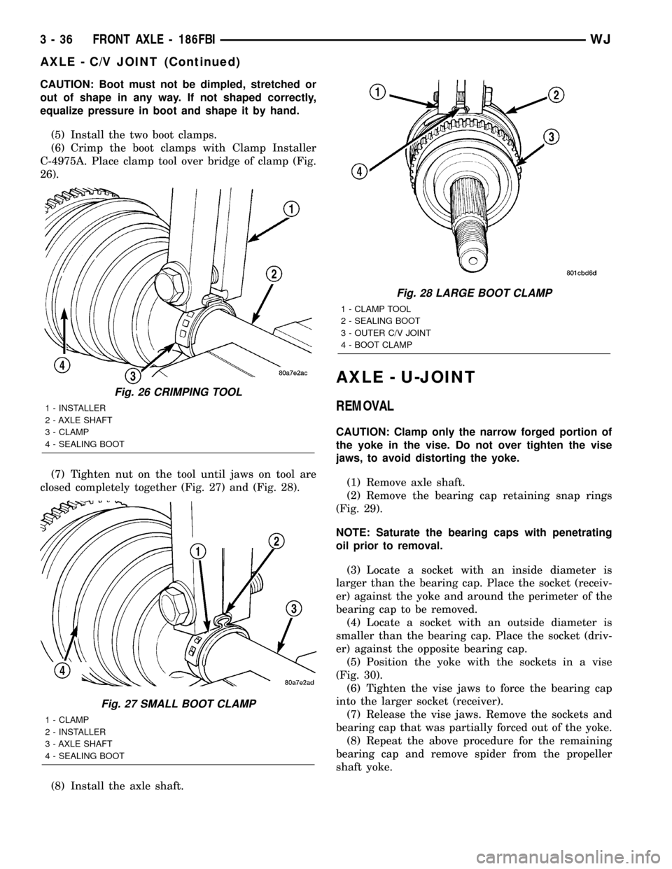
(5) Install the two boot clamps.
(6) Crimp the boot clamps with Clamp Installer
C-4975A. Place clamp tool over bridge of clamp (Fig.
26).
(7) Tighten nut on the tool until jaws on tool are
closed completely together (Fig. 27) and (Fig. 28).
(8) Install the axle shaft.
AXLE - U-JOINT
REMOVAL
CAUTION: Clamp only the narrow forged portion of
the yoke in the vise. Do not over tighten the vise
jaws, to avoid distorting the yoke.
(1) Remove axle shaft.
(2) Remove the bearing cap retaining snap rings
(Fig. 29).
NOTE: Saturate the bearing caps with penetrating
oil prior to removal.
(3) Locate a socket with an inside diameter is
larger than the bearing cap. Place the socket (receiv-
er) against the yoke and around the perimeter of the
bearing cap to be removed.
(4) Locate a socket with an outside diameter is
smaller than the bearing cap. Place the socket (driv-
er) against the opposite bearing cap.
(5) Position the yoke with the sockets in a vise
(Fig. 30).
(6) Tighten the vise jaws to force the bearing cap
into the larger socket (receiver).
(7) Release the vise jaws. Remove the sockets and
bearing cap that was partially forced out of the yoke.
(8) Repeat the above procedure for the remaining
bearing cap and remove spider from the propeller
shaft yoke.
Fig. 26 CRIMPING TOOL
1 - INSTALLER
2 - AXLE SHAFT
3 - CLAMP
4 - SEALING BOOT
Fig. 27 SMALL BOOT CLAMP
1 - CLAMP
2 - INSTALLER
3 - AXLE SHAFT
4 - SEALING BOOT
Fig. 28 LARGE BOOT CLAMP
1 - CLAMP TOOL
2 - SEALING BOOT
3 - OUTER C/V JOINT
4 - BOOT CLAMP
3 - 36 FRONT AXLE - 186FBIWJ
AXLE - C/V JOINT (Continued)
Page 85 of 2199

²New Bearings: 1.7 to 3.4 N´m (15 to 30 in. lbs.).
(9) Install propeller shaft with reference marks
aligned.
(10) Install brake rotors and calipers.
(11) Add gear lubricant if necessary.
(12) Install wheel and tire assemblies.
(13) Lower vehicle.
DIFFERENTIAL
REMOVAL
(1) Raise and support the vehicle.
(2) Remove lubricant fill hole plug from the differ-
ential housing cover.
(3) Remove differential cover and drain lubricant.
(4) Clean the housing cavity with a flushing oil,
light engine oil or lint free cloth.Never use water,
steam, kerosene or gasoline for cleaning.
(5) Remove hub bearings and axle shafts.
(6) Note installation reference letters stamped on
the bearing caps and housing machined sealing sur-
face (Fig. 38).
(7) Loosen the differential bearing cap bolts.
(8) Position Spreader W-129-B with Adapter Kit
6987B on differential locating holes (Fig. 39). Install
hold down clamps and tighten the tool turnbuckle
finger-tight.
Fig. 37 PINION COMPANION FLANGE
1 - COMPANION FLNAGE
2 - DIFFERENTIAL HOUSING
3 - SPANNER WRENCH
Fig. 38 BEARING CAP IDENTIFICATION
1 - REFERENCE LETTERS
2 - REFERENCE LETTERS
Fig. 39 DIFFERENTIAL SPREADER LOCATION
1 - DIFFERENTIAL HOUSING
2 - ADAPTER
3 - HOLD DOWN CLAMPS
4 - SPREADER
5 - TURNBUCKLE
3 - 40 FRONT AXLE - 186FBIWJ
COLLAPSIBLE SPACER (Continued)
Page 88 of 2199

INSTALLATION
NOTE: If replacement differential bearings or differ-
ential case are being installed, differential side
bearing shim requirements may change. Refer to
Adjustments (Differential Bearing Preload and Gear
Backlash) to determine the proper shim selection.
(1) Position Spreader W-129-B with Adapter Kit
6987B on differential locating holes. Install hold
down clamps and tighten the tool turnbuckle finger-
tight.
(2) Install a Pilot Stud C-3288-B at the left side of
the differential housing. Attach Dial Indicator C-3339
to pilot stud. Load the indicator plunger against the
opposite side of the housing and zero the indicator.
(3) Spread the housing enough to install the case
in the housing. Measure the distance with the dial
indicator.
CAUTION: Never spread the housing over 0.50 mm
(0.020 in). If housing is over-spread, it could dis-
torted and damaged the housing.
(4) Remove the dial indicator.
(5) Install differential case in the housing (Fig.
46). Make sure the differential bearing cups remain
on the bearings and the preload shims remain
between the face of the bearing cup and housing. Tap
the differential case to ensure the bearings cups and
shims are fully seated in the housing.
CAUTION: On a Vari-lokTdifferential the oil feed
tube must be pointed at the bottom of the housing.
If differential is installed with the oil feed tube
pointed at the top, the anti-rotation tabs will be
damaged.
(6) Install the bearing caps at their original loca-
tions (Fig. 47).
(7) Loosely install differential bearing cap bolts.
(8) Remove axle housing spreader.
(9) Tighten the bearing cap bolts to 61 N´m (45 ft.
lbs.).
(10) Install the hub bearings and axle shafts.
Fig. 46 DIFFERENTIAL CASE REMOVAL
1 - DIFFERENTIAL HOUSING
2 - DIFFERENTIAL CASE
3 - BEARING CUPS
Fig. 47 Bearing Cap Reference
1 - REFERENCE LETTERS
2 - REFERENCE LETTERS
WJFRONT AXLE - 186FBI 3 - 43
DIFFERENTIAL (Continued)
Page 120 of 2199

(7) Check rotating torque with an inch pound
torque wrench (Fig. 44). The rotating torque of the
pinion gear should be, the reading recorded during
removal plus an additional 0.56 N´m (5 in. lbs.).
(8) Install propeller shaft with reference marks
align.
(9) Install rear brake calipers and rotors (Refer to
5 - BRAKES/HYDRAULIC/MECHANICAL/ROTORS
- INSTALLATION).
(10) Add gear lubricant, if necessary.
(11) Install wheel and tire assemblies.
(12) Remove supports and lower vehicle.
DIFFERENTIAL
REMOVAL
(1) Raise and support vehicle.
(2) Remove fill hole plug from the differential
housing cover.
(3) Remove differential housing cover and drain
fluid.
(4) Clean the housing cavity with flushing oil, light
engine oil or lint free cloth.
NOTE: Do not use water, steam, kerosene or gaso-
line for cleaning.
(5) Remove axle shafts.(6)
Note the reference letters stamped on the bearing
caps and housing machined sealing surface (Fig. 45).
(7) Loosen the differential bearing cap bolts.
(8) Position Spreader W-129-B with Adapter Kit
6987B on differential locating holes (Fig. 46). Install
holddown clamps and tighten the turnbuckle finger-
tight.
Fig. 44 PINION ROTATING TORQUE
1 - TORQUE WRENCH
2 - PINION YOKE
Fig. 45 BEARING CAP REFERENCE
1 - REFERENCE LETTERS
2 - REFERENCE LETTERS
Fig. 46 SPREADER LOCATION
1 - DIFFERENTIAL HOUSING
2 - DOWEL
3 - SAFETY HOLD DOWN
4 - SPREADER
5 - TURNBUCKLE
WJREAR AXLE - 198RBI 3 - 75
COLLAPSIBLE SPACER (Continued)
Page 122 of 2199

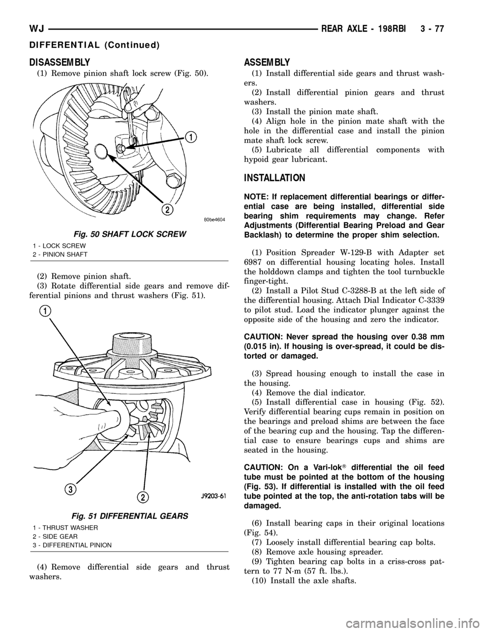
DISASSEMBLY
(1) Remove pinion shaft lock screw (Fig. 50).
(2) Remove pinion shaft.
(3) Rotate differential side gears and remove dif-
ferential pinions and thrust washers (Fig. 51).
(4) Remove differential side gears and thrust
washers.
ASSEMBLY
(1) Install differential side gears and thrust wash-
ers.
(2) Install differential pinion gears and thrust
washers.
(3) Install the pinion mate shaft.
(4) Align hole in the pinion mate shaft with the
hole in the differential case and install the pinion
mate shaft lock screw.
(5) Lubricate all differential components with
hypoid gear lubricant.
INSTALLATION
NOTE: If replacement differential bearings or differ-
ential case are being installed, differential side
bearing shim requirements may change. Refer
Adjustments (Differential Bearing Preload and Gear
Backlash) to determine the proper shim selection.
(1) Position Spreader W-129-B with Adapter set
6987 on differential housing locating holes. Install
the holddown clamps and tighten the tool turnbuckle
finger-tight.
(2) Install a Pilot Stud C-3288-B at the left side of
the differential housing. Attach Dial Indicator C-3339
to pilot stud. Load the indicator plunger against the
opposite side of the housing and zero the indicator.
CAUTION: Never spread the housing over 0.38 mm
(0.015 in). If housing is over-spread, it could be dis-
torted or damaged.
(3) Spread housing enough to install the case in
the housing.
(4) Remove the dial indicator.
(5) Install differential case in housing (Fig. 52).
Verify differential bearing cups remain in position on
the bearings and preload shims are between the face
of the bearing cup and the housing. Tap the differen-
tial case to ensure bearings cups and shims are
seated in the housing.
CAUTION: On a Vari-lokTdifferential the oil feed
tube must be pointed at the bottom of the housing
(Fig. 53). If differential is installed with the oil feed
tube pointed at the top, the anti-rotation tabs will be
damaged.
(6) Install bearing caps in their original locations
(Fig. 54).
(7) Loosely install differential bearing cap bolts.
(8) Remove axle housing spreader.
(9) Tighten bearing cap bolts in a criss-cross pat-
tern to 77 N´m (57 ft. lbs.).
(10) Install the axle shafts.
Fig. 50 SHAFT LOCK SCREW
1 - LOCK SCREW
2 - PINION SHAFT
Fig. 51 DIFFERENTIAL GEARS
1 - THRUST WASHER
2 - SIDE GEAR
3 - DIFFERENTIAL PINION
WJREAR AXLE - 198RBI 3 - 77
DIFFERENTIAL (Continued)
Page 160 of 2199

NOTE: If more than 380 N´m (280 ft. lbs.) torque is
required to crush the collapsible spacer, the spacer
is defective and must be replaced.
(7) Check rotating torque with an inch pound
torque wrench (Fig. 44). The rotating torque of the
pinion gear should be, the reading recorded during
removal plus an additional 0.56 N´m (5 in. lbs.).
(8)
Install propeller shaft with reference marks align.
(9) Install rear brake rotors and calipers.
(10) Add gear lubricant, if necessary.
(11) Install wheel and tire assemblies.
(12) Remove supports and lower vehicle.
DIFFERENTIAL
REMOVAL
(1) Raise and support vehicle.
(2) Remove fill hole plug from the differential
housing cover.
(3) Remove differential housing cover and drain
fluid.
(4) Clean the housing cavity with flushing oil, light
engine oil or lint free cloth.
NOTE: Do not use water, steam, kerosene or gaso-
line for cleaning.
(5) Remove axle shafts.(6)
Note the reference letters stamped on the bearing
caps and housing machined sealing surface (Fig. 45).
(7) Loosen the differential bearing cap bolts.
(8) Position Spreader W-129-B with Adapter Kit
6987B on differential locating holes (Fig. 46). Install
holddown clamps and tighten the turnbuckle finger-
tight.
Fig. 44 PINION ROTATING TORQUE
1 - TORQUE WRENCH
2 - PINION YOKE
Fig. 45 BEARING CAP REFERENCE
1 - REFERENCE LETTERS
2 - REFERENCE LETTERS
Fig. 46 SPREADER LOCATION
1 - DIFFERENTIAL HOUSING
2 - DOWEL
3 - SAFETY HOLD DOWN
4 - SPREADER
5 - TURNBUCKLE
WJREAR AXLE - 226RBA 3 - 115
COLLAPSIBLE SPACER (Continued)
Page 162 of 2199

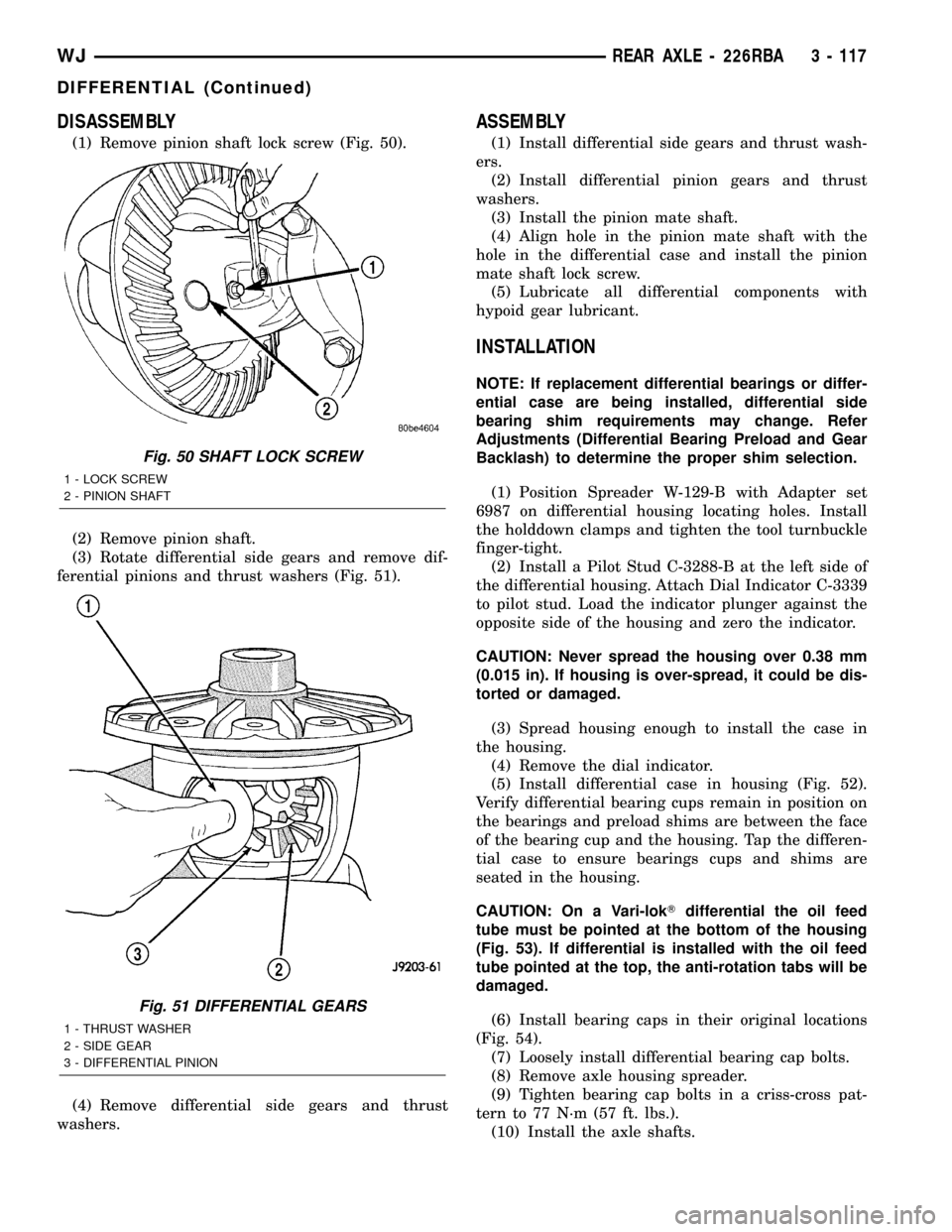
DISASSEMBLY
(1) Remove pinion shaft lock screw (Fig. 50).
(2) Remove pinion shaft.
(3) Rotate differential side gears and remove dif-
ferential pinions and thrust washers (Fig. 51).
(4) Remove differential side gears and thrust
washers.
ASSEMBLY
(1) Install differential side gears and thrust wash-
ers.
(2) Install differential pinion gears and thrust
washers.
(3) Install the pinion mate shaft.
(4) Align hole in the pinion mate shaft with the
hole in the differential case and install the pinion
mate shaft lock screw.
(5) Lubricate all differential components with
hypoid gear lubricant.
INSTALLATION
NOTE: If replacement differential bearings or differ-
ential case are being installed, differential side
bearing shim requirements may change. Refer
Adjustments (Differential Bearing Preload and Gear
Backlash) to determine the proper shim selection.
(1) Position Spreader W-129-B with Adapter set
6987 on differential housing locating holes. Install
the holddown clamps and tighten the tool turnbuckle
finger-tight.
(2) Install a Pilot Stud C-3288-B at the left side of
the differential housing. Attach Dial Indicator C-3339
to pilot stud. Load the indicator plunger against the
opposite side of the housing and zero the indicator.
CAUTION: Never spread the housing over 0.38 mm
(0.015 in). If housing is over-spread, it could be dis-
torted or damaged.
(3) Spread housing enough to install the case in
the housing.
(4) Remove the dial indicator.
(5) Install differential case in housing (Fig. 52).
Verify differential bearing cups remain in position on
the bearings and preload shims are between the face
of the bearing cup and the housing. Tap the differen-
tial case to ensure bearings cups and shims are
seated in the housing.
CAUTION: On a Vari-lokTdifferential the oil feed
tube must be pointed at the bottom of the housing
(Fig. 53). If differential is installed with the oil feed
tube pointed at the top, the anti-rotation tabs will be
damaged.
(6) Install bearing caps in their original locations
(Fig. 54).
(7) Loosely install differential bearing cap bolts.
(8) Remove axle housing spreader.
(9) Tighten bearing cap bolts in a criss-cross pat-
tern to 77 N´m (57 ft. lbs.).
(10) Install the axle shafts.
Fig. 50 SHAFT LOCK SCREW
1 - LOCK SCREW
2 - PINION SHAFT
Fig. 51 DIFFERENTIAL GEARS
1 - THRUST WASHER
2 - SIDE GEAR
3 - DIFFERENTIAL PINION
WJREAR AXLE - 226RBA 3 - 117
DIFFERENTIAL (Continued)
Page 218 of 2199

ELECTRIC BRAKE
DESCRIPTION
The electronic brake distribution (EBD) functions
like a rear proportioning valve. The EBD system uses
the ABS system to control the slip of the rear wheels
in partial braking range. The braking force of the
rear wheels is controlled electronically by using the
inlet and outlet valves located in the HCU.
OPERATION
Upon entry into EBD the inlet valve for the rear
brake circuit is switched on so that the fluid supply
from the master cylinder is shut off. In order to
decrease the rear brake pressure the outlet valve for
the rear brake circuit is pulsed. This allows fluid to
enter the low pressure accumulator (LPA) in the
HCU resulting in a drop in fluid pressure to the rear
brakes. In order to increase the rear brake pressure
the outlet valve is switched off and the inlet valve is
pulsed. This increases the pressure to the rear
brakes. This will continue until the required slip dif-
ference is obtained. At the end of EBD braking (no
brake application) the fluid in the LPA drains back to
the master cylinder by switching on the outlet valve
and draining through the inlet valve check valve. At
the same time the inlet valve is switched on to pre-
vent a hydraulic short circiut in case of another
brake application.
The EBD will remain functional during many ABS
fault modes. If the red and amber warning lamps are
illuminated the EBD may have a fault.
FRONT WHEEL SPEED
SENSOR
DESCRIPTION
A wheel speed sensor is used at each wheel. The
front sensors are mounted to the steering knuckles.
The rear sensors are mounted at the outboard end of
the axle. Tone wheels are mounted to the outboard
ends of the front and rear axle shafts. The gear type
tone wheel serves as the trigger mechanism for each
sensor.
OPERATION
The sensors convert wheel speed into a small digi-
tal signal. The CAB sends 12 volts to the sensors.
The sensor has an internal magneto resistance
bridge that alters the voltage and amperage of the
signal circuit. This voltage and amperage is changed
by magnetic induction when the toothed tone wheel
passes the wheel speed sensor. This digital signal issent to the CAB. The CAB measures the voltage and
amperage of the digital signal for each wheel.
REMOVAL
(1) Raise and support the vehicle.
(2) Remove the front wheel sensor mounting bolt
(Fig. 1).
(3) Remove the sensor from the steering knuckle.
(4) Disengage the sensor wire from the brackets
(Fig. 1)on the steering knuckle.
(5) Disconnect the sensor from the sensor harness
(Fig. 2)and (Fig. 3).
(6) Remove the sensor and wire.
INSTALLATION
(1) Install the sensor on the steering knuckle.
(2) Apply Mopar Lock N' Seal or Loctitet242 to
the sensor mounting bolt. Use new sensor bolt if orig-
inal bolt is worn or damaged.
(3) Install the sensor mounting bolt and tighten
bolt to 12-14 N´m (106-124 in. lbs.).
(4) Engage the grommets on the sensor wire to the
steering knuckle brackets.
(5) Connect the sensor wire to the harness connec-
tor.
(6) Check the sensor wire routing. Be sure the
wire is clear of all chassis components and is not
twisted or kinked at any spot.
(7) Remove the support and lower vehicle.
Fig. 1 Sensor Location
1 - BRACKET
2 - BRACKET
3 - WHEEL SPEED SENSOR
4 - MOUNTING BOLT
WJBRAKES - ABS 5 - 43