2002 JEEP GRAND CHEROKEE Hydraulic fan
[x] Cancel search: Hydraulic fanPage 266 of 2199

(4) Remove two radiator mounting bolts.
(5) Disconnect both transmission cooler lines from
radiator.
(6) Disconnect electrical connector for the fan con-
trol solenoid.
(7) Disconnect the power steering cooler line from
cooler and filter.
(8) Disconnect the radiator upper and lower hoses.
(9) Disconnect the overflow hose from radiator.
(10) Remove the air inlet duct at the grill.(11) The lower part of radiator is equipped with
two alignment dowel pins (Fig. 35). They are located
on the bottom of radiator tank and fit into rubber
grommets. These rubber grommets are pressed into
the radiator lower crossmember.
WARNING: THE AIR CONDITIONING SYSTEM (IF
EQUIPPED) IS UNDER A CONSTANT PRESSURE
EVEN WITH THE ENGINE OFF. REFER TO REFRIG-
ERANT WARNINGS IN, HEATING AND AIR CONDI-
TIONING BEFORE HANDLING ANY AIR
CONDITIONING COMPONENT.
NOTE: The radiator and radiator cooling fan can be
removed as an assembly. It is not necessary to
remove the cooling fan before removing or install-
ing the radiator.
(12) Disconnect the two high pressure fluid lines
at the hydraulic fan drive.
(13) Disconnect the low pressure return hose at
the hydraulic fan drive.
(14) Gently lift up and remove radiator from vehi-
cle. Be careful not to scrape the radiator fins against
any other component. Also be careful not to disturb
the air conditioning condenser (if equipped).
CLEANING
Clean radiator fins With the engine cold, apply cold
water and compressed air to the back (engine side) of
Fig. 32 Hose Clamp Tool - Typical
1 - HOSE CLAMP TOOL 6094
2 - HOSE CLAMP
Fig. 33 Clamp Number/Letter Location - Typical
1 - TYPICAL CONSTANT TENSION HOSE CLAMP
2 - CLAMP NUMBER/LETTER LOCATION
3 - TYPICAL HOSE
Fig. 34 Air Seals - Typical
1 - AIR DAM
2 - RADIATOR
3 - AIR DAM
4 - A/C CONDENSER
5 - AIR SEAL
WJENGINE 7 - 43
RADIATOR - 4.7L (Continued)
Page 267 of 2199

the radiator to flush the radiator and/or A/C con-
denser of debris.
INSPECTION
The radiator cooling fins should be checked for
damage or deterioration. Inspect cooling fins to make
sure they are not bent or crushed, these areas result
in reduced heat exchange causing the cooling system
to operate at higher temperatures. Inspect the plastic
end tanks for cracks, damage or leaks.
Inspect the radiator neck for damage or distortion.
INSTALLATION
CAUTION: Before installing the radiator or A/C con-
denser, be sure the radiator-to-body and radiator-to-
A/C condenser rubber air seals (Fig. 39) are
properly fastened to their original positions. These
are used at the top, bottom and sides of the radia-
tor and A/C condenser. To prevent overheating,
these seals must be installed to their original posi-
tions.
(1) Equipped with air conditioning: Gently lower
the radiator and fan shroud into the vehicle. Guide
the two radiator alignment dowels through the holes
in the rubber air seals first and then through the A/C
support brackets (Fig. 40). Continue to guide thealignment dowels into the rubber grommets located
in lower radiator crossmember. The holes in the
L-shaped brackets (located on bottom of A/C con-
denser) must be positioned between bottom of rubber
air seals and top of rubber grommets.
(2) Connect the radiator upper and lower hoses
and hose clamps to radiator.
CAUTION: The tangs on the hose clamps must be
positioned straight down.
(3) Install coolant reserve/overflow tank hose at
radiator.
(4) Connect both transmission cooler lines at the
radiator.
(5) Install both radiator mounting bolts.
(6) Install air inlet duct at grill.
(7) Attach electric connector for hydraulic fan con-
trol solenoid.
(8) Install the grill (Refer to 23 - BODY/EXTERI-
OR/GRILLE - INSTALLATION).
(9) Connect the two high pressure lines to the
hydraulic fan drive. Tighten
1¤2in. pressure line fit-
ting to 49 N´m (36 ft. lbs.). and the 3/8 in. pressure
line fitting to 29 N´m (21.5 ft. lbs.).
(10) Connect the low pressure hose to the hydrau-
lic fan drive. Position the spring clamp.
(11) Connect the power steering filter hoses to the
filter. Install new hose clamps.
(12) Rotate the fan blades (by hand) and check for
interference at fan shroud.
(13) Refill cooling system (Refer to 7 - COOLING -
STANDARD PROCEDURE).
(14) Refill the power steering reservoir and bleed
air from system (Refer to 19 - STEERING/PUMP -
STANDARD PROCEDURE).
(15) Connect battery cable at battery.
(16) Start and warm engine. Check for leaks.
RADIATOR - 4.0L
DESCRIPTION
All vehicles are equipped with a cross flow type
radiator with plastic side tanks (Fig. 36).
Plastic tanks, while stronger than brass, are sub-
ject to damage by impact, such as from tools or
wrenches. Handle radiator with care.
REMOVAL
WARNING: DO NOT REMOVE THE CYLINDER
BLOCK DRAIN PLUGS OR LOOSEN THE RADIATOR
DRAINCOCK WITH THE SYSTEM HOT AND UNDER
PRESSURE. SERIOUS BURNS FROM COOLANT
CAN OCCUR. REFER TO COOLING SYSTEM DRAIN-
ING.
Fig. 35 Radiator Alignment Dowels - Typical
1 - RADIATOR
2 - ALIGNMENT DOWEL
3 - RADIATOR LOWER ISOLATOR
4 - RADIATOR LOWER CROSSMEMBER
7 - 44 ENGINEWJ
RADIATOR - 4.7L (Continued)
Page 1123 of 2199
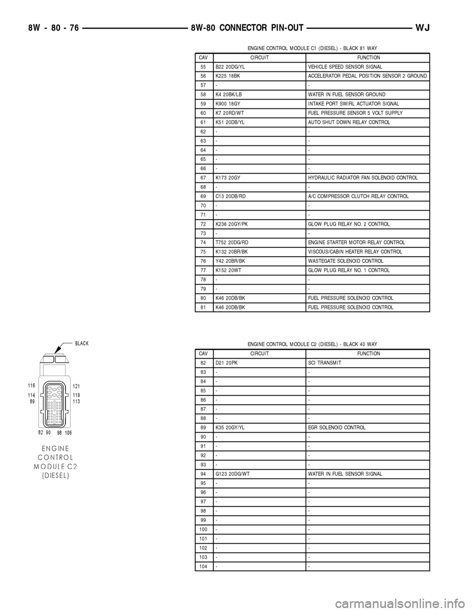
ENGINE CONTROL MODULE C1 (DIESEL) - BLACK 81 WAY
CAV CIRCUIT FUNCTION
55 B22 20DG/YL VEHICLE SPEED SENSOR SIGNAL
56 K225 18BK ACCELERATOR PEDAL POSITION SENSOR 2 GROUND
57 - -
58 K4 20BK/LB WATER IN FUEL SENSOR GROUND
59 K900 18GY INTAKE PORT SWIRL ACTUATOR SIGNAL
60 K7 20RD/WT FUEL PRESSURE SENSOR 5 VOLT SUPPLY
61 K51 20DB/YL AUTO SHUT DOWN RELAY CONTROL
62 - -
63 - -
64 - -
65 - -
66 - -
67 K173 20GY HYDRAULIC RADIATOR FAN SOLENOID CONTROL
68 - -
69 C13 20DB/RD A/C COMPRESSOR CLUTCH RELAY CONTROL
70 - -
71 - -
72 K236 20GY/PK GLOW PLUG RELAY NO. 2 CONTROL
73 - -
74 T752 20DG/RD ENGINE STARTER MOTOR RELAY CONTROL
75 K132 20BR/BK VISCOUS/CABIN HEATER RELAY CONTROL
76 Y42 20BR/BK WASTEGATE SOLENOID CONTROL
77 K152 20WT GLOW PLUG RELAY NO. 1 CONTROL
78 - -
79 - -
80 K46 20DB/BK FUEL PRESSURE SOLENOID CONTROL
81 K46 20DB/BK FUEL PRESSURE SOLENOID CONTROL
ENGINE CONTROL MODULE C2 (DIESEL) - BLACK 40 WAY
CAV CIRCUIT FUNCTION
82 D21 20PK SCI TRANSMIT
83 - -
84 - -
85 - -
86 - -
87 - -
88 - -
89 K35 20GY/YL EGR SOLENOID CONTROL
90 - -
91 - -
92 - -
93 - -
94 G123 20DG/WT WATER IN FUEL SENSOR SIGNAL
95 - -
96 - -
97 - -
98 - -
99 - -
100 - -
101 - -
102 - -
103 - -
104 - -
8W - 80 - 76 8W-80 CONNECTOR PIN-OUTWJ
Page 1131 of 2199
HORN NO. 2 - BLACK 2 WAY
CAV CIRCUIT FUNCTION
1 Z307 18BK GROUND
2 X2 18DG/RD HORN RELAY OUTPUT
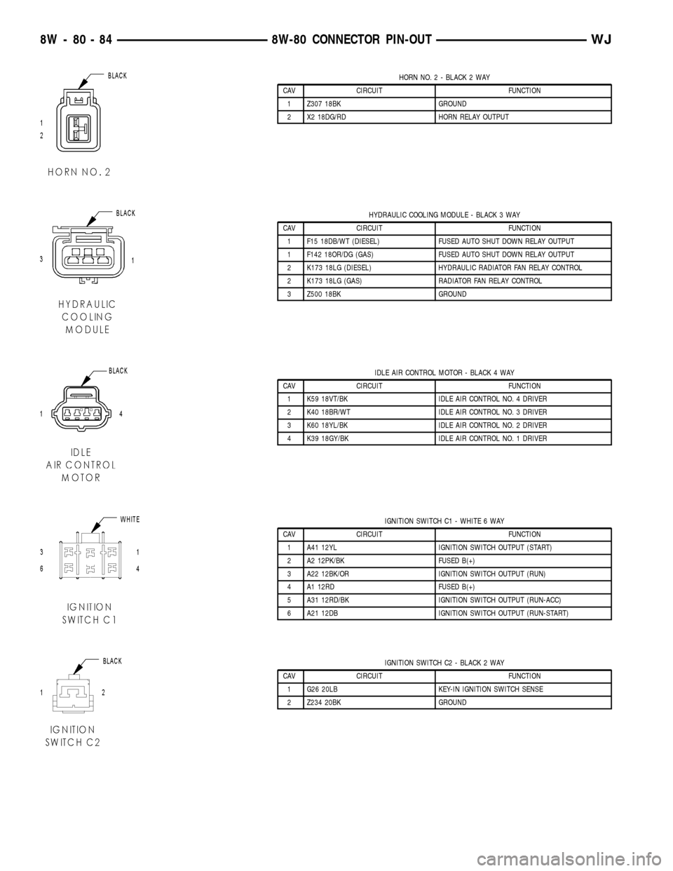
HYDRAULIC COOLING MODULE - BLACK 3 WAY
CAV CIRCUIT FUNCTION
1 F15 18DB/WT (DIESEL) FUSED AUTO SHUT DOWN RELAY OUTPUT
1 F142 18OR/DG (GAS) FUSED AUTO SHUT DOWN RELAY OUTPUT
2 K173 18LG (DIESEL) HYDRAULIC RADIATOR FAN RELAY CONTROL
2 K173 18LG (GAS) RADIATOR FAN RELAY CONTROL
3 Z500 18BK GROUND
IDLE AIR CONTROL MOTOR - BLACK 4 WAY
CAV CIRCUIT FUNCTION
1 K59 18VT/BK IDLE AIR CONTROL NO. 4 DRIVER
2 K40 18BR/WT IDLE AIR CONTROL NO. 3 DRIVER
3 K60 18YL/BK IDLE AIR CONTROL NO. 2 DRIVER
4 K39 18GY/BK IDLE AIR CONTROL NO. 1 DRIVER
IGNITION SWITCH C1 - WHITE 6 WAY
CAV CIRCUIT FUNCTION
1 A41 12YL IGNITION SWITCH OUTPUT (START)
2 A2 12PK/BK FUSED B(+)
3 A22 12BK/OR IGNITION SWITCH OUTPUT (RUN)
4 A1 12RD FUSED B(+)
5 A31 12RD/BK IGNITION SWITCH OUTPUT (RUN-ACC)
6 A21 12DB IGNITION SWITCH OUTPUT (RUN-START)
IGNITION SWITCH C2 - BLACK 2 WAY
CAV CIRCUIT FUNCTION
1 G26 20LB KEY-IN IGNITION SWITCH SENSE
2 Z234 20BK GROUND
8W - 80 - 84 8W-80 CONNECTOR PIN-OUTWJ
Page 1257 of 2199
WARNING: USE EXTREME CAUTION WHEN THE
ENGINE IS OPERATING. DO NOT STAND IN A
DIRECT LINE WITH THE FAN. DO NOT PUT YOUR
HANDS NEAR THE PULLEYS, BELTS OR FAN. DO
NOT WEAR LOOSE CLOTHING.
(48) Start the engine, inspect for leaks and correct
the fluid levels, as necessary.
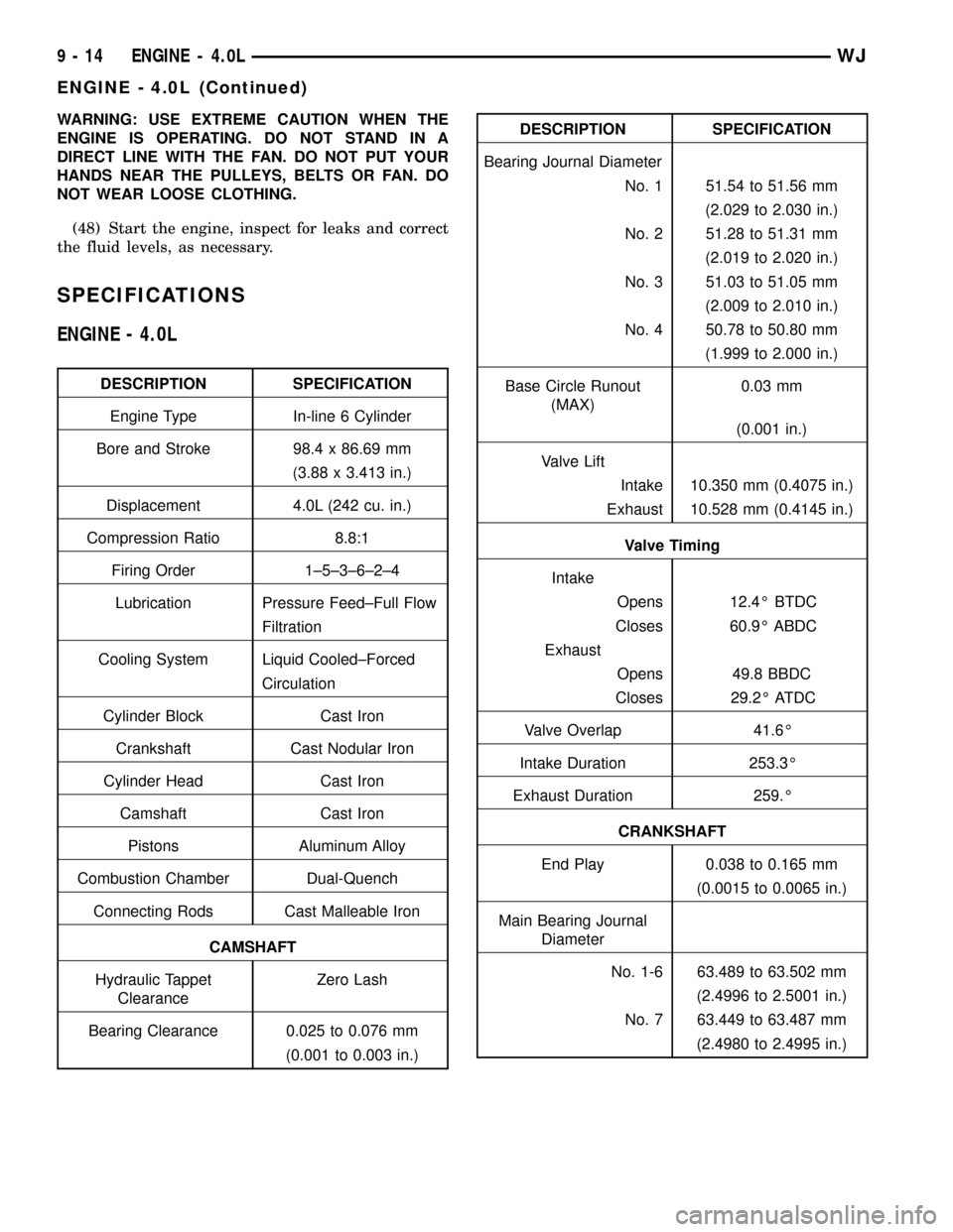
SPECIFICATIONS
ENGINE - 4.0L
DESCRIPTION SPECIFICATION
Engine Type In-line 6 Cylinder
Bore and Stroke 98.4 x 86.69 mm
(3.88 x 3.413 in.)
Displacement 4.0L (242 cu. in.)
Compression Ratio 8.8:1
Firing Order 1±5±3±6±2±4
Lubrication Pressure Feed±Full Flow
Filtration
Cooling System Liquid Cooled±Forced
Circulation
Cylinder Block Cast Iron
Crankshaft Cast Nodular Iron
Cylinder Head Cast Iron
Camshaft Cast Iron
Pistons Aluminum Alloy
Combustion Chamber Dual-Quench
Connecting Rods Cast Malleable Iron
CAMSHAFT
Hydraulic Tappet
ClearanceZero Lash
Bearing Clearance 0.025 to 0.076 mm
(0.001 to 0.003 in.)
DESCRIPTION SPECIFICATION
Bearing Journal Diameter
No. 1 51.54 to 51.56 mm
(2.029 to 2.030 in.)
No. 2 51.28 to 51.31 mm
(2.019 to 2.020 in.)
No. 3 51.03 to 51.05 mm
(2.009 to 2.010 in.)
No. 4 50.78 to 50.80 mm
(1.999 to 2.000 in.)
Base Circle Runout
(MAX)0.03 mm
(0.001 in.)
Valve Lift
Intake 10.350 mm (0.4075 in.)
Exhaust 10.528 mm (0.4145 in.)
Valve Timing
Intake
Opens 12.4É BTDC
Closes 60.9É ABDC
Exhaust
Opens 49.8 BBDC
Closes 29.2É ATDC
Valve Overlap 41.6É
Intake Duration 253.3É
Exhaust Duration 259.É
CRANKSHAFT
End Play 0.038 to 0.165 mm
(0.0015 to 0.0065 in.)
Main Bearing Journal
Diameter
No. 1-6 63.489 to 63.502 mm
(2.4996 to 2.5001 in.)
No. 7 63.449 to 63.487 mm
(2.4980 to 2.4995 in.)
9 - 14 ENGINE - 4.0LWJ
ENGINE - 4.0L (Continued)
Page 1480 of 2199
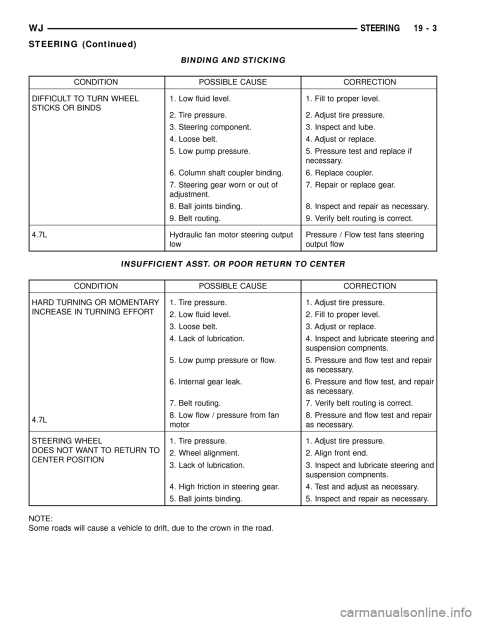
BINDING AND STICKING
CONDITION POSSIBLE CAUSE CORRECTION
DIFFICULT TO TURN WHEEL
STICKS OR BINDS1. Low fluid level. 1. Fill to proper level.
2. Tire pressure. 2. Adjust tire pressure.
3. Steering component. 3. Inspect and lube.
4. Loose belt. 4. Adjust or replace.
5. Low pump pressure. 5. Pressure test and replace if
necessary.
6. Column shaft coupler binding. 6. Replace coupler.
7. Steering gear worn or out of
adjustment.7. Repair or replace gear.
8. Ball joints binding. 8. Inspect and repair as necessary.
9. Belt routing. 9. Verify belt routing is correct.
4.7L Hydraulic fan motor steering output
lowPressure / Flow test fans steering
output flow
INSUFFICIENT ASST. OR POOR RETURN TO CENTER
CONDITION POSSIBLE CAUSE CORRECTION
HARD TURNING OR MOMENTARY
INCREASE IN TURNING EFFORT1. Tire pressure. 1. Adjust tire pressure.
2. Low fluid level. 2. Fill to proper level.
3. Loose belt. 3. Adjust or replace.
4. Lack of lubrication. 4. Inspect and lubricate steering and
suspension compnents.
5. Low pump pressure or flow. 5. Pressure and flow test and repair
as necessary.
6. Internal gear leak. 6. Pressure and flow test, and repair
as necessary.
7. Belt routing. 7. Verify belt routing is correct.
4.7L8. Low flow / pressure from fan
motor8. Pressure and flow test and repair
as necessary.
STEERING WHEEL
DOES NOT WANT TO RETURN TO
CENTER POSITION1. Tire pressure. 1. Adjust tire pressure.
2. Wheel alignment. 2. Align front end.
3. Lack of lubrication. 3. Inspect and lubricate steering and
suspension compnents.
4. High friction in steering gear. 4. Test and adjust as necessary.
5. Ball joints binding. 5. Inspect and repair as necessary.
NOTE:
Some roads will cause a vehicle to drift, due to the crown in the road.
WJSTEERING 19 - 3
STEERING (Continued)
Page 1482 of 2199
(8) Start engine and let idle long enough to circu-
late power steering fluid through flow/pressure test
gauge.
(9) Shut off the engine and check the fluid level,
add fluid as necessary. Start engine again and let
idle.
(10) The initial pressure reading should be
345-552 kPa (50-80 psi). If pressure is higher inspect
the hoses for restrictions and repair as necessary.
(11) Increase the engine speed to 1500 RPM and
read the flow meter. The reading should be 2.4 - 2.8
GPM, if the reading is below this specification the
pump should be replaced.
CAUTION: This next step involves testing maximum
pump pressure output and flow control valve oper-
ation. Do not leave valve closed for more than three
seconds as the pump could be damaged.
(12) Close valve fully three times for three seconds
and record highest pressure indicated each time.All
three readings must be at pump relief pressure
specifications and within 345 kPa (50 psi) of
each other.
²Pressures above specifications but not within
345 kPa (50 psi) of each other, replace pump.
²Pressures within 345 kPa (50 psi) of each other
but below specifications, replace pump.
CAUTION: Do not force the pump to operate against
the stops for more than 2 to 4 seconds at a time
because, pump damage will result.
(13) Open the test valve and turn the steering
wheel to the extreme left and right positions against
the stops. Record the highest pressure reading at
each position. Compare readings to the pump specifi-
cations chart. If pressures readings are not within 50
psi. of each other, the gear is leaking internally and
must be repaired.
GEAR INLET SPECIFICATIONS 4.0L & 4.7L
ENGINERELIEF
PRESSURE 50FLOW RATE
(GPM)
4.0L 9653 kPa (1400 psi)
1500 RPM 2.4 - 2.8
GPM
4.7L 9653 kPa (1450 psi)
PUMP MOTOR SPECIFICATIONS 4.7L
ENGINERELIEF
PRESSURE 50FLOW RATE
(GPM)
4.7L 9653 kPa (1900 psi)1100 RPM 2.4-2.8
GPM Minium
@ 200 psi
DIAGNOSIS AND TESTING - 4.7L -
HYDRAULIC
The following procedures are used to test the oper-
ation of the power steering and hydraulic fan sys-
tems on the vehicle. This test will provide the gallons
per minute (GPM) or flow rate of the power steering
pump along with any maximum relief pressure. Per-
form test anytime a power steering system problem
is present. This test will determine if the power
steering pump, hydraulic fan, and power steering
gear are not functioning properly. It will also deter-
mine if the flow coming out of the hydraulic fan
motor is sufficient for the power steering gear. The
following pressure and flow test is performed using
the Power Steering Analyzer Tool kit 6815 (Fig. 2)
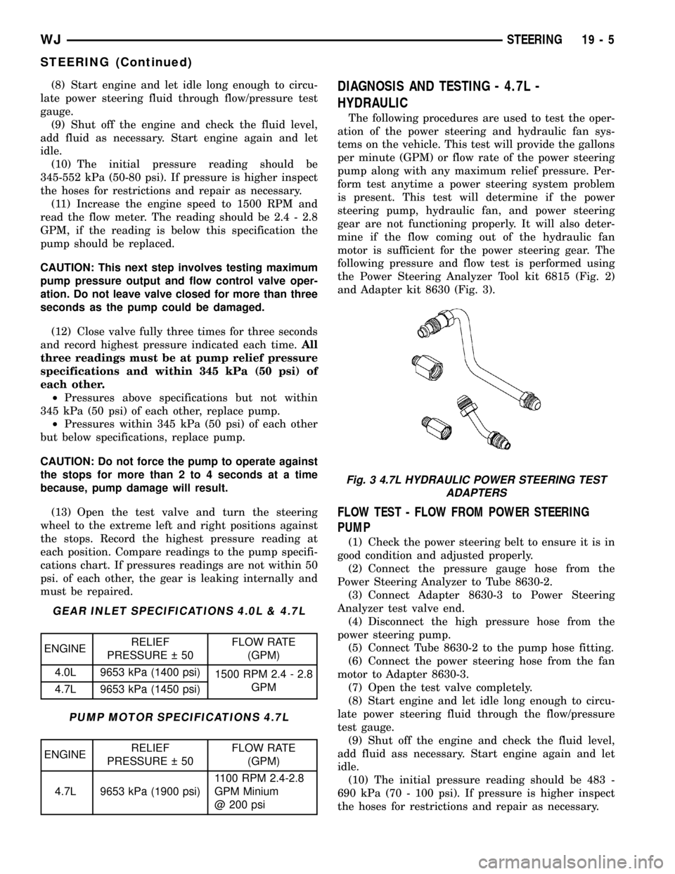
and Adapter kit 8630 (Fig. 3).
FLOW TEST - FLOW FROM POWER STEERING
PUMP
(1) Check the power steering belt to ensure it is in
good condition and adjusted properly.
(2) Connect the pressure gauge hose from the
Power Steering Analyzer to Tube 8630-2.
(3) Connect Adapter 8630-3 to Power Steering
Analyzer test valve end.
(4) Disconnect the high pressure hose from the
power steering pump.
(5) Connect Tube 8630-2 to the pump hose fitting.
(6) Connect the power steering hose from the fan
motor to Adapter 8630-3.
(7) Open the test valve completely.
(8) Start engine and let idle long enough to circu-
late power steering fluid through the flow/pressure
test gauge.
(9) Shut off the engine and check the fluid level,
add fluid ass necessary. Start engine again and let
idle.
(10) The initial pressure reading should be 483 -
690 kPa (70 - 100 psi). If pressure is higher inspect
the hoses for restrictions and repair as necessary.
Fig. 3 4.7L HYDRAULIC POWER STEERING TEST
ADAPTERS
WJSTEERING 19 - 5
STEERING (Continued)
Page 1483 of 2199
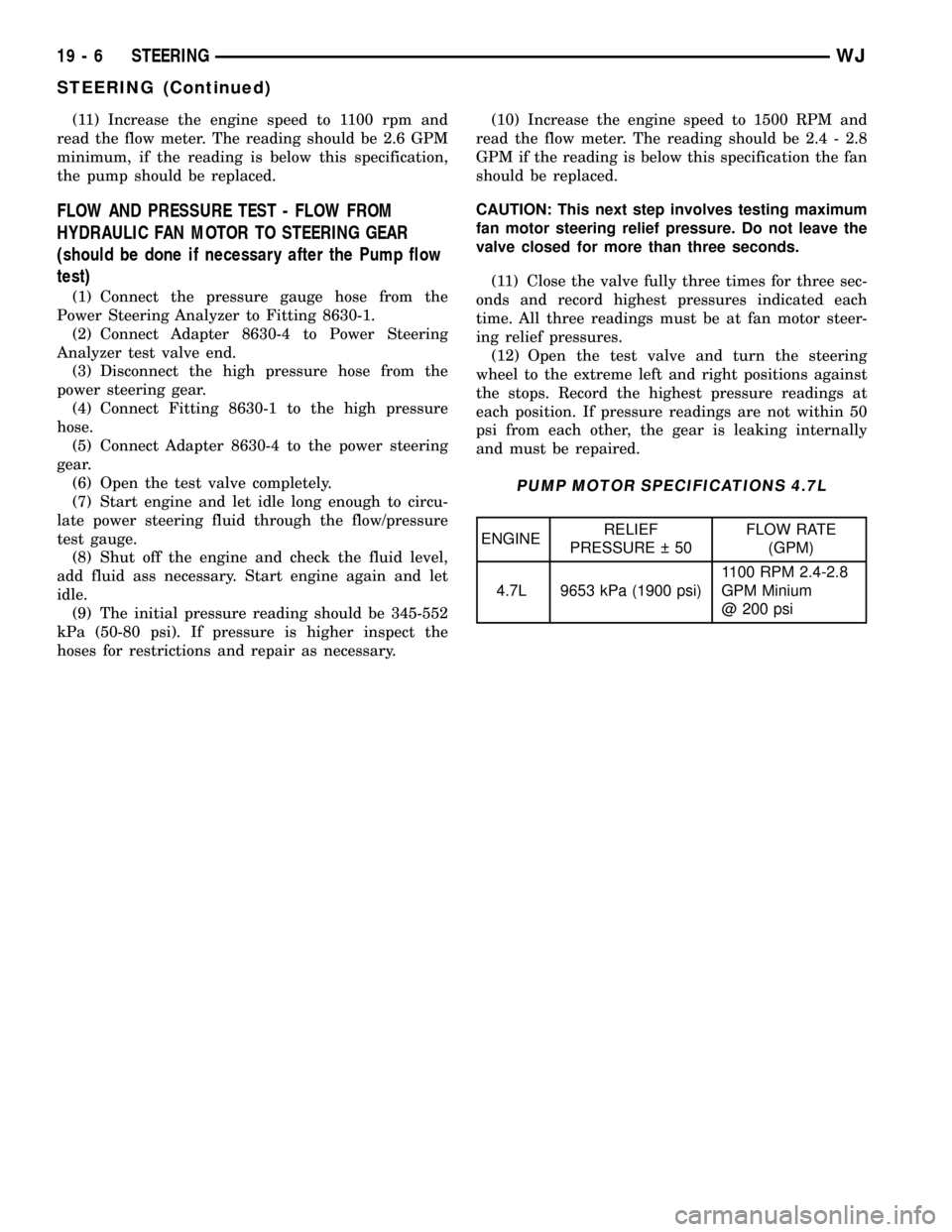
(11) Increase the engine speed to 1100 rpm and
read the flow meter. The reading should be 2.6 GPM
minimum, if the reading is below this specification,
the pump should be replaced.
FLOW AND PRESSURE TEST - FLOW FROM
HYDRAULIC FAN MOTOR TO STEERING GEAR
(should be done if necessary after the Pump flow
test)
(1) Connect the pressure gauge hose from the
Power Steering Analyzer to Fitting 8630-1.
(2) Connect Adapter 8630-4 to Power Steering
Analyzer test valve end.
(3) Disconnect the high pressure hose from the
power steering gear.
(4) Connect Fitting 8630-1 to the high pressure
hose.
(5) Connect Adapter 8630-4 to the power steering
gear.
(6) Open the test valve completely.
(7) Start engine and let idle long enough to circu-
late power steering fluid through the flow/pressure
test gauge.
(8) Shut off the engine and check the fluid level,
add fluid ass necessary. Start engine again and let
idle.
(9) The initial pressure reading should be 345-552
kPa (50-80 psi). If pressure is higher inspect the
hoses for restrictions and repair as necessary.(10) Increase the engine speed to 1500 RPM and
read the flow meter. The reading should be 2.4 - 2.8
GPM if the reading is below this specification the fan
should be replaced.
CAUTION: This next step involves testing maximum
fan motor steering relief pressure. Do not leave the
valve closed for more than three seconds.
(11) Close the valve fully three times for three sec-
onds and record highest pressures indicated each
time. All three readings must be at fan motor steer-
ing relief pressures.
(12) Open the test valve and turn the steering
wheel to the extreme left and right positions against
the stops. Record the highest pressure readings at
each position. If pressure readings are not within 50
psi from each other, the gear is leaking internally
and must be repaired.
PUMP MOTOR SPECIFICATIONS 4.7L
ENGINERELIEF
PRESSURE 50FLOW RATE
(GPM)
4.7L 9653 kPa (1900 psi)1100 RPM 2.4-2.8
GPM Minium
@ 200 psi
19 - 6 STEERINGWJ
STEERING (Continued)